8mm Cast Tool Plate Design Advice
-
Hi guys, and thank you for your comments.
I'd actually been advised of the Mandala rose works bed by @T3P3Tony.
This is an option I'm considering regarding the countersunk ring magnets. With this idea it would require thinner and stronger magnets due them being screwed to the bed, rather than some form of adhesive. There would also be no issues (or shouldn't be if loctite'd in place), with finding and adhesive or failure.
@deckingman said in 8mm Cast Tool Plate Design Advice:
The latter method defeats the purpose of buying expensive tooling plate in the first place.
This is one of my concerns, by defeating the object of a tool plate with drilling holes in it.
-
@Dizzwold ah, be interesting to hear Tony's thoughts on them then.
I tried embedding magnets from behind once, pocketed so there was 1mm of material left. They weren't strong enough so it was a waste of time.
I used high temp silicone to stick them in. -
The thought I had was to use 6mm deep magnet and leave 2mm on top, but with your failure it maybe best just to go with the large PEI sheet.
As @deckingman has previously commented and written-up on, and currently uses, you can always use a glass plate on top.
-
My experience with PEI was anything but happy. PEI is a 'wear surface' that can be easily damaged and it's a royal pain to remove that surface if it was glued on. In my case I installed the PEI on a glass plate to allow replacement. What is even more troubling (and this is based on my own experience so YMMV), getting the PEI installed flat is a BIG problem. I don't know how flat PEI is but in my experience, glass is not really that flat so no matter what you do, you will need to use height compensation. Also, a tiny air bubble getting trapped in the adhesive can cause you all kinds of grief. The PEI that i attempted to use came as a separate sheet of glue (marked with ' 3M' all over it) and the PEI so twice the possibility of air bubbles getting trapped.
The real kicker for me was the tendency for the PEI to curl at higher temperatures and the glue layer letting go. The force of the PEI curling was very strong and if I recall correctly, anything over about 100C for the build plate resulted in disaster. This was a fairly thick, maybe 1 mm (it's been a long time) sheet of PEI and I would never attempt to use a relatively thick sheet again. Both the PEI and the glue came from Amazon so it is debatable if either or both were made with chinesium in them or what. I still have the glass plate with the PEI stashed away someplace to remind me to never do this again.
I have no experience with spring steel build plates but I have no confidence in these either. In my humble opinion, unless you get the surface of the magnet being absolutely level with the surface of the build plate, you will have issues with surface distortion. I do not know if Mandala Rose surface grinds his plate after the magnets are installed but you pretty much double the price .....I have not seen complaints of people experiencing the issues that I had so who knows, maybe I was just lucky.
I have a cast aluminum tooling plate and I use a plain sheet of glass on top of it. I have a 500mm* 500mm printer with a fairly thick plate because of the overall size and I need to give the printer some time after the tooling plate is at temperature before the glass surface is at temperature. If I do not give it enough time (5 min is good), the print does not stick. I use no adhesion enhancers.
On my 300300 printer I have a thinner sheet of glass and the surface of the glass seems to be up to temperature if I wait to heat the hot end until the build surface is reported to be at temperature. The bit of delay heating the hot end seems enough to equalize the glass surface temperature.
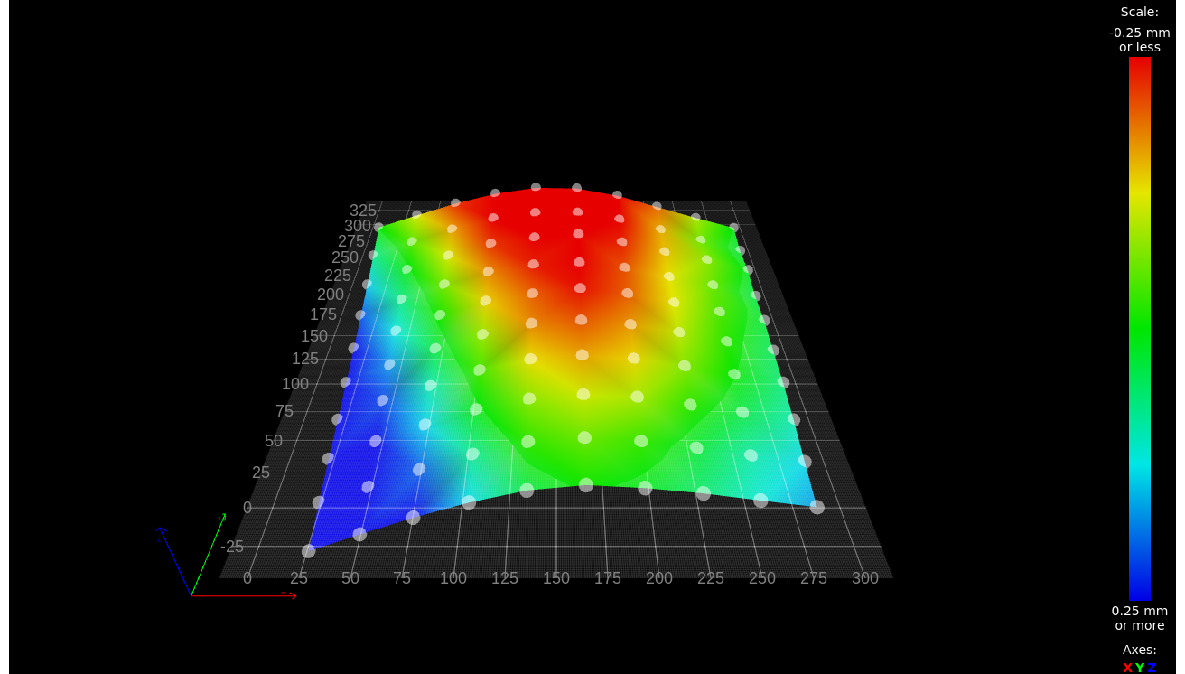
I have seen some amazingly flat print surfaces being shown here but I do not recall if those surface maps were the bare aluminum or the actual print surface on top of the aluminum. I am not that lucky. Here is my 300300 surface measured with 100 points with glass installed:
My tooling plate is supported by three points - a single point in the center of one side and two points at each corner of the other side. This allows for tilt to be adjusted. All three points are shown in green (perfect) and everything else is just crap. I am really glad that I have surface compensation!
One of these days I will run the surface mapping without the glass to see how flat the tooling plate is.Edit:
OK, so now I am starting to doubt myself - I can't recall if the plate I used was a cast tooling plate. It might have been a plain old 6061 piece of aluminum. I brought in two plates, one tooling plate and one plain plate and I might have used the plain plate to do the first milling run as a test but I never did a second run. I will run a surface scan in the next few days to see what the bare aluminum plate looks like. -
Just to throw my 2P worth in.... I run glass on ali and had trouble with the glass taking on the plates shape and having inconsistent flatness. Both solved by dabbing heat transfer compound onto the ali plate in a grid then placing the glass on top. Better heat transfer is a bonus (no waiting for the glass to heat) but the real kicker is the HTC is viscous enough to let the glass sit on it without running away, so the glass can retain it's own (very good) flatness without following the plate. It also stops the glass easily sliding laterally, should the nozzle contact a blob or suchlike. I still run bed comp but I'm well under 0.1mm and so consistent it's almost pointless to remap. I use it to tell me if one of the two Z screws has dropped really, though I should stop being lazy and set them up independent and get the machine to sort.
Removal is easy enough, just pull a single strand of wire through like a cheese wire to break the HTC. Clean and reapply. If you get a hump in the middle, just heat up and put some weight on. Leave it half hour and the glass naturally want to go back to flat, squishing the HTC where it needs to.
I'm not using anything expensive: stock Ender 5 Plus plate and glass bed. Also pulled the same trick on my much Frankensteined Anet A8, the bed of which is truly atrocious but perfectly serviceable with HTC and borosilicate glass slapped on top. It doesn't even have a probe or bed compensation! At the end of the day, ali is terrible at dimensional stability when heated. It's also full of stresses whether billet or cast. If it's not really well annealed to normalise it, those stresses will appear every time heat is applied. Tooling plates should be better than any old cheap slab, of course.
Hope someone finds it helpful, thought I'd throw into the discussion. -
Just my twopence worth on the topic of using glass as a build surface. Others may disagree of course but this is my personal experience having tried almost every other surface.
For me it is the perfect solution. I use 6mm thick float glass which is surprisingly difficult to break. When I first built my printer I had the glass toughened. This proved to be a mistake as the toughening process distorts the glass. So plain, unadulterated float glass works best for me. Glass is cheap, and readily available so I have 3 sheets. This means that once a print has finished, I can quickly and easily swap out one sheet, and start another print. This is important to me because my thick, insulated bed takes and awfully long time to cool.
I do use 3D Lac. This is primarily because it allows me to lay down the first layer at normal print speed (usually 80mm/sec). That saves a lot of time especially when printing large parts. When experimenting with high volumetric flow rates, I have printed at up to 300 mm/sec - including the first layer. I don't know of any other print surface or treatment product that will allow me to do that, but please correct me if you know otherwise.
I don't use any form of flatness or levelling compensation. The only time I even check for level is if I've taken the printer apart and transported it somewhere. No mesh compensation, no levelling, nothing - I just turn on the printer, home, heat then print (and I can print edge to edge). Not trying to brag or anything - just saying how it is for me.
-
My printer's bed is 8mm tooling plate with a 0.7 mm layer of PEI. The plate is 300x300 mm but has ears for the kinematic mounting points. The heater is 300x300 mm so the entire printable surface of the plate is heated. I would recommend against using a heater that is smaller than the print area because the temperature will fall off as you approach the edges of the plate and you may have trouble getting prints to stick reliably near the edges. It may also be cause for the plate to bow when heated, but that can be corrected if you use a bed sensor and sufficiently complex Z axis construction.
I print TPU, ABS, PETG, and very rarely, PLA, and find that everything sticks to PEI. Yes, it wears as you pry prints from the surface, but it can be easily buffed up with a melamine sponge. A few drops of IPA at the base of the print help release it from the PEI after the print is finished. The adhesive that holds the PEI on the plate tends to let go after a couple years so you periodically have to replace it. I suspect that sealing the edges with silicone will prevent the adhesive from drying out and letting go of the PEI.
When you order the bed heater, get one without any adhesive and glue it down using high temperature silicone.
-
@deckingman said in 8mm Cast Tool Plate Design Advice:
Not trying to brag or anything - just saying how it is for me.
You might not be trying but you are succeeding

Does the 3Dlac let go when the build plate cools down? Do you apply it before every print or does it last a long time once applied ? -
@jens55 said in 8mm Cast Tool Plate Design Advice:
Does the 3Dlac let go when the build plate cools down?
Yes absolutely. Parts just fall off or at worse need a light tap. One caveat - don't use 3D Lac with Woodfill filaments - you need a hammer and chisel to remove the part which will destroy it. There may be other filaments that react this way but I haven't found any - "normal" PET-G, ABS, ASA, PLA etc all work fine for me.
Do you apply it before every print or does it last a long time once applied ?
I apply ever print. I'm fairly sure, but not certain that any residue sticks to the part rather than the glass. I occasionally have to scrape excess residue off glass which has been applied outside the print area - once every 30 or 40 prints or so. But it's easy to do and I find a sharp 2 inch wood chisel works well as a scraper or a dedicated gasket scraper.
-
For completeness sake ....
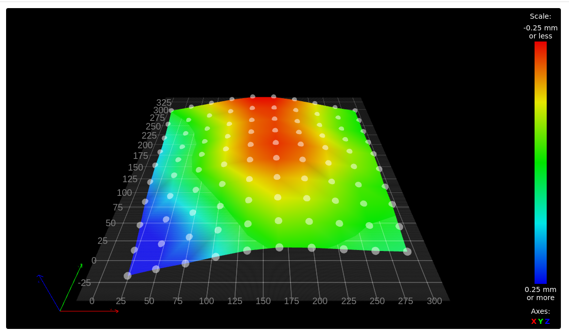
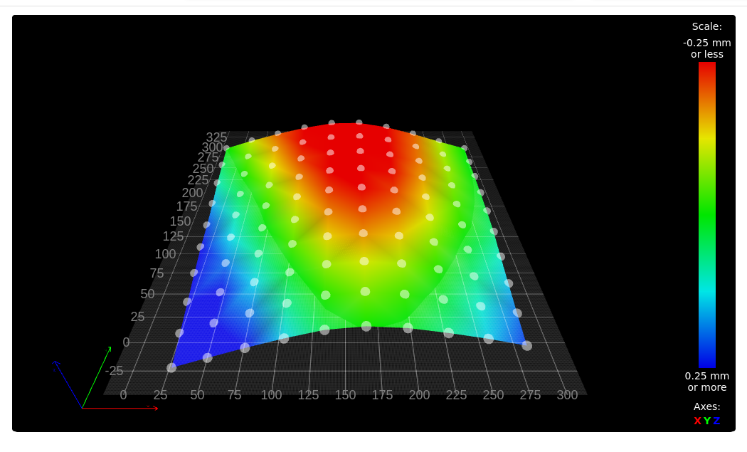
My plate is 7 mm and it is normal aluminum and not cast tool plate. Below is the height map without the glass plate installed (ie measured on bare aluminum). It is eerily similar to the height map with the glass plate installed. It would seem to indicate that the glass plate either conforms to the build plate or that this particular glass plate has, over time, conformed to the build plate. Glass is after all a liquid .....
So I was curious. I re-installed the glass plate but rotated 180 degrees. The result confirms that the glass plate takes on the shape of the bed. This is a fairly thin glass plate ....!

-
@jens55 said in 8mm Cast Tool Plate Design Advice:
............ Glass is after all a liquid .....
Ahh - that's where you might be going wrong - suggest you reduce the bed temperature to below 1700 Deg C where the glass will become solid.

This is a fairly thin glass plate ....!
On a more serious note, suggest you use thicker glass and ignore the naysayers who will tell you that glass is an insulator - if it was we wouldn't need to double or triple glaze our homes to keep them warm.

-
@deckingman, I sit corrected. A quick internet search seems to suggest that the glass being liquid is an urban myth. I was always told that really old windows were thicker at the bottom than the top which proved that theory. Unfortunately it turns out that manufacturing methods at the time were such that glass varied in thickness and the thicker section was always oriented towards the bottom of the window.
Just to be on the safe side, I will do as you suggest and reduce my build plate temperature by roughly 1635 degrees.The word 'insulator' is a relative term. Compared to aluminum or copper, glass is a poor conductor of heat. Compared to something like asbestos (or for that matter a gas filled space between two glass panes), it probably conducts heat a lot better. It definitively takes more time to heat a glass plate sitting on top of an aluminum bed than it would take to heat an aluminum plate sitting on top of that same aluminum bed (assuming intimate contact between plates).
I use mirror glass tiles as a 300*300 bed - extremely cheap but I have no choice on thickness.
If I was really curious, I would take my cast tooling plate, lay it on top of the existing bed and do a surface analysis. Alas, I am not THAT curious.
-
@Dizzwold
Why not use magnetic sheet instead of multiple magnets? You can buy a high-temp mag-sheet and use your springsteel PEI surface.
That's what I did on my last build, but the PEI easily crackes from part removing (might not like the flexible steel?)
So I replaced the springsteel with 1mm Pertinax held in place by a ferro-sheet. Don't go for two mag sheets, the one I picked has a north/south alternating magnetic pattern, which is very strong.
Pertinax is so far the best surface, but same as glass it takes a while to heat up. -
So, an interesting development ....
I put a cast tool plate over top of my bed and did a surface analysis - turns out that it appears to be pretty much identical as per the previously posted surface maps. This leads me to believe that there is something weird going on with my motion system. I am running a Jubilee printer with two linear y rails and one cross-rail which is X. Z also uses linear rails and height is done via three individual motors.
It doesn't make sense that the cast tool plate would show the same surface map unless something is out of whack with the gantry. At this point, I am guessing that my cross rail (x) has a slight bow in it -
@jens55 it's common for the X gantry to sag slightly under the weight of the print carriage. This leads to a height map that appears to show the bed being higher at mid X values.
-
@dc42, the Jubilee has it's z sensor on the carriage and the bed map is done without a tool head mounted. I doubt that it the weight is much more than 50 gr. Now once a tool head is mounted, I can see a bit of deflection even though the gantry on the Jubilee seems very sturdy.

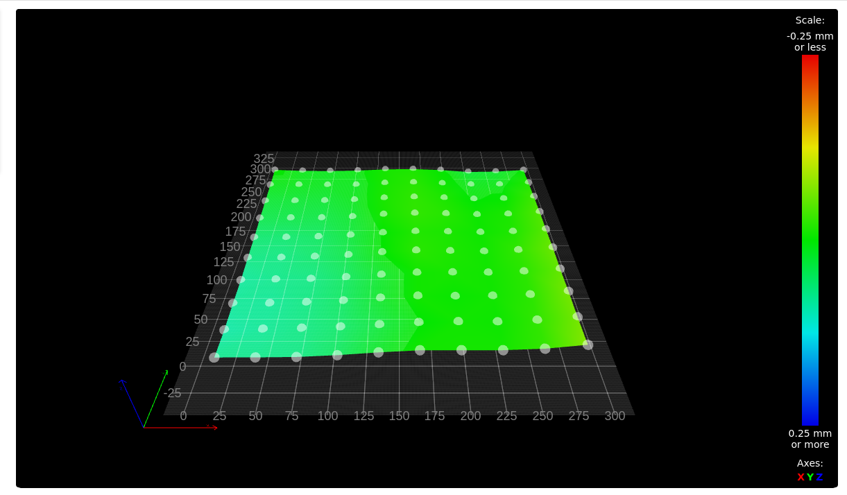
As it turned out, loosening all the screws on the crossbar and tightening them ever so carefully from the center out got me a much improved picture. At the back things are out +- 0.02 mm and at the front it varies between +0.072 and - 0.073 mm. Very much improved. I am gobsmacked that the mounting screws of the x rail could cause so much distortion ... I guess when you are dealing with tiny dimensions, normal ways of thinking do not apply.Next I will go back to my original build plate which is not a cast tooling plate and see how that looks. I will run it both hot and cold, just for the heck of it.
-
@jens55 said in 8mm Cast Tool Plate Design Advice:
I am gobsmacked that the mounting screws of the x rail could cause so much distortion ...
Maybe there was a different room temp when you tightened them the 1st time?
If possible, I leave one end of the crossbar floating to be able to compensate fluctuations. -
Thanks all for the advice, this is very timely... I'm about to rebuild my TronXY as a VzBoT, but with a Jubilee-style kinematic bed.
Ian
-
Okay, thank you.
Pertinax, just looked this up. It's apparently a Trade Name for FR-2, or in other-words a PCB without the copper layer.
I do remember seeing a video from Makers Muse a while back and he recommend FR-2 or something similar.Regarding using these stick-on magnetic sheets. I was under the impression that these could cause undulations, and this was the reasoning behind milling pockets on the underside of the tool plate for neodymium magnets.
I don't know weather to go with neodymium magnets now or not. You've got to get the correct strength in force, at the correct depth, and have enough of them strategically placed.
@droftarts said in 8mm Cast Tool Plate Design Advice:
I'm about to rebuild my TronXY as a VzBoT, but with a Jubilee-style kinematic bed
Do you have any idea on what magnets are used on the jubilee bed and at what depth?
@mrehorstdmd said in 8mm Cast Tool Plate Design Advice:
everything sticks to PEI
Do you not bother with any adhesives, and would adhesives not help to save the PEI sheet?
I know I'm going to do as @deckingman has previously advised and drill a 3mm hole from one edge, as deep as I can towards the centre for the thermistor and also screw a TCO to the edge as well.
-
@Dizzwold I don't use any adhesives on the PEI at all. Everything I print with sticks. I sometimes have trouble getting larger TPU prints to let go. That's where a few drops of IPA help the print to release. I use a very sharp Olfa scraper to pry prints up. The PEI surface gets scratched up a bit, so I occasionally smooth it with a melamine sponge and frequently clean it at room temperature with IPA. The PEI that's on the bed now was installed when I built the machine, so 4 or 5 years ago. It lasts. The adhesive that holds it down is good for about 2 years, then it let's go of the PEI. So you just clean off the bed plate and the PEI and reassemble with a fresh sheet of adhesive. Then just a tram check/set and z=0 set and you're done. I suspect that sealing the edges of the PEI/adhesive with silicone would prevent the adhesive from letting go of the PEI. I'll be replacing the adhesive on my printer in the next week or two and will try it and see.
If you have the heater secured to the bed plate in a reliable mechanical way, you can mount the TCO on the plate. But if you use adhesive to mount it on the underside of the bed plate, the TCO should be fastened to the heater, not the bed plate. If the adhesive fails and the heater drops away from the bed plate, the plate mounted TCO won't do its job. I mounted the TCO on the heater in my printer using high temperature silicone, the same stuff I used to mount the heater on the bed plate.