Linear rail headaches
-
Hi all,
I'm trying to figure out if what I am experiencing with linear rail is normal, or if I am just getting some bad luck.
I recently put together a second printer, to help support my business, in case my main printer goes down. My main printer is kind of my hobby printer, that has been upgraded and modified continually over the years. It's my own design, a corexy with 4 independent leadscrews, and a gantry utilizing linear rod. The gantry on this machine is heavy and bulky, so for my second machine I decided to re-design it to use linear rail, and so I could eventually incorporate a toolchanger.
The old machine, with cheap amazon linear rod, poor linear rod mounts, and really crappy 3d printed linear bearings has a maximum deviation of -0.017 / 0.045mm over the entire bed.

The new machine, after trying to align the linear rail as best I can, using a multitude of different approaches, isn't anywhere even close to those numbers. Maximum Deviations -0.052 / 0.055 mm.

As you can see, there is a massive low spot on the bed, and a visible high spot. Now, I know you may be tempted to say that it's my bed, or my build surface. However, I am probing directly onto a glass plate with a euclid probe on both machines. Both machines are using the same size e3d high temperature heated bed. I even take the glass plate from one machine to the other, and orient it in the same direction, and still get these results.
So my question is, why does everybody use linear rails, if it's basically like dealing with a wet noodle that can't be aligned properly? My first machine, which objectively has a worse design when looking at the machine as a whole, can hold tighter tolerance with cheap ass linear rods from amazon.
Any ideas? I'm pulling my hair out here and feeling like I wasted 3 grand for nothing.
-
@Surgikill
Do both printers use the same DWC version?
The deviation numbers of the new printer aren't so bad. It's just the heightmap-picture that looks scary.
Maybe they have just changed the colormapping in DWC? -
@Surgikill said in Linear rail headaches:
why does everybody use linear rails, if it's basically like dealing with a wet noodle that can't be aligned properly
I have not tried to use linear rails without mounting them on something that was itself, relatively flat. whats the rail mounted on?
-
@Surgikill Photos of the machines...?
-
The first thing you have to consider is the quality of your linear rails. Then you have to be sure that you are mounting the linear rail over a FLAT surface, so quality of your aluminium extrusion (if you are using that) is very important. And last but VERY important: the adjustment of that rail to the support structure. Many people use the higher torque they can use on every screw. That is sooooo wrong because by doing that you will force the perfectly straight linear rail to bend to adjust itselt to the deviation your support may have. They correct way to do it is follow the manufacturer guide (in the case of hiwin is 0.8nm). In that way the linear rail will be secured to the support, but if the suppor has a small deviation from plain, the linealrail will still be straight. That is why the linear rails have sooo many screws
These are some advices I can give (I have used linear rails on all my printers, always hiwin brand) -
@o_lampe no, but the numbers are there, and the crap machine has about half the deviation.
@T3P3Tony is mounted on 20x20 aluminum extrusion.
@mrehorstdmd I'll post those up when I get a chance.
@Tinchus see, that's exactly opposite of what two resellers have told me so far. Both of them have said that there's no tolerance for straightness on the rail, and that it's meant to conform to the reference surface. I know that's bullshit, because there HAS to be a manufacturing tolerance, even if it is just a general tolerance. So short of getting something specifically machined, it seems that I'm SOL.
-
@Surgikill the tips im shareing with you come straight from hiwin, I took training from them. This wau I describe, is at least the proper way to install a hiwing rail.
In fact what you haev been told is not what it is in the product code when you order a rail, again at least in hiwin. One of the codes that you need to define when you order a hiwin rails, states the straightness quality you are requesting (and of course, the more straight you want, the expensive will be). If you want I can share with you alter the codes Im using right now -
@Tinchus I would be interested on your training did you talk about pre load of the mgn carriers, im trying to reduce play in the x axis and wondered if hiwin had some recomendations?
-
@Tinchus Are you talking about these tolerances?
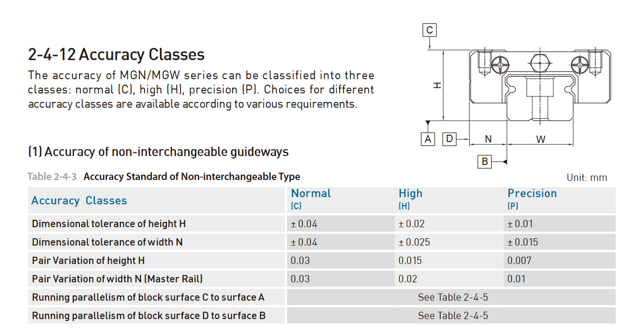
What I was told, is that the tolerance of width N and height H has no effect on the straightness of the rail, at least for the MGN series rails. There are some rails that are wide enough that there is a straightness tolerance, but everything I have been told is that there is no tolerance for straightness, and that there won't be any guaranteed straightness.
This is one response I received.
"So typically single bolt hole row linear guides do not have a straightness tolerance. The rails do have a dimensional tolerance which is typically +/-0.0002" or so for width and height. The reason for this is that at any significant length (ie 10x the rail width or so), the straightness of the rail installation is determined by the accuracy of the mounting surface or mounting procedure. It is a bit like asking the straightness of a piece of wet noodle. It can certainly be made straight, but it just depends on how it is aligned or what it is sitting on.
For super high accuracy applications, you would want to follow the procedure in the catalog where you machine a grooved shoulder that the rail sits within. You clamp the rail to the machined edge and then tighten down the bolts. This ensure the rail matches the straightness of the machined edge. In practice, very few installations do this especially with the MG series rails. Instead, you would use a precision ground parallel or some other straight edge and tighten the bolt holes sequentially while clamping the rail to the straight edge. Even then, this is uncommon. Many users just loosely thread the bolts in,push the rail fully against the bolts while tightening without any straight edge at all. This does get you straight enough for many applications. What are you aiming for on straightness and over what span?"
This is the response I received from a different company.
"Linear rails get their straightness from what they are mounted to. Linear rails should ideally be mounted against a reference edge, see here:
https://www.tuli-shop.com/blog/the-do-s-and-don-ts-of-linear-rail-alignment.html
Though some 3D printer designers don’t heed that, resulting in the alignment needing to be done manually.
The +/-0.023mm refers to something different than straightness. If the rail is mounting on a perfectly flat surface, the position of the carriage would be expected to deviate only 0.023mm in any direction while being slid along the rail. It is a measurement of the machining accuracy of the height of the rail. Some more reading here:
https://www.linearmotiontips.com/how-to-choose-linear-guide-accuracy/
guide rails tend to conform to the surface on which they’re mounted. In order to realize the full benefits of a higher accuracy linear guide, the mounting surface should be machined at least to the same standard as the guide."
I'm not saying you're wrong, but I have people telling me conflicting things, so I can't make heads or tails of it. I know there is a tolerance somewhere, or these rails would be shaped like a piece of wet spaghetti.
@mrehorstdmd Here's the old machine. Probably has 3k hours on it with no real maintenance to the motion platform besides oiling and cleaning up debris/dust.

Here's the new machine. Probably about 10 hours on it.

-
hi i was asking about the preload Z0,Z1,Zf this is the tolerance of the balls between the rail and MGN carriage,
-
@moth4017 I'm not sure if that would fix your issue. What exactly is the issue you are having?
-
@Surgikill im trying to reduce the movement in the x axis i guess it would be the "Roll" or "MR" on the hiwin data sheet
-
@moth4017 Do you have a post about it that you can link? If not you should make one and post some pictures of your setup.
-
@Surgikill Going back to your original problem. Looking at the design of your two machines I'd be looking closely to see if the various cables/pipes/whatever are causing your print head to tilt slightly as it moves around the print area. You seem to have a lot of stuff connected to the head and your older design with widely spaced rods may have been better at resisting any twisting force that is being imparted than a single linear rail (with plastic parts between it and the head) is able to. Perhaps the wider (and possibly stiffer) air delivery tube (I'm guessing that is what it is), may be adding more "pull" as well. The actual variation you are seeing is very small and so very little movement would be needed.
-
The torsional stiffness of 2020 extrusions is already low, but when their ends are supported by printed parts you're in double trouble...
I've added 12mm carbon rods to stiffen my weak gantry, almost no weight penalty, but big improvement. Look for square carbon profiles, if you want to be compatible with 2020 mounting options.
Mixing aluminum extrusion with carbon rods might result in a bimetal issue if not propperly connected. Let the extrusion float on one end.Alternatively go for 2040 extrusions, they're much stiffer than 2020.
-
@Surgikill It looks like you're using 4 screws to lift/level the bed. I see a bit of red at all four corners of the surface map, indicating some distortion there. Try moving the bed up and down a bit and remap the surface a few times. Does it come out close to the same every time or does it vary? If the map varies, I'd guess that the 4 screws are not quite perfect (either the screws themselves or the motors driving them) and maybe distorting the subframe the bed is mounted on. It might be alignment of the rails- putting 4 of them parallel to each other, and keeping them that way, especially with plastic mounts, is tricky business.
I see the four small screws that hold the bed plate to the subframe, and are all pass through solid spacers that go to printed plastic mounts screwed to the subframe. If there's any error in the positioning of the plastic parts or in the spacers (or distortion in the subframe) it will distort the bed. A three point mount would be a better way to go if you can manage it. 3 points define a plane, not four, and a plane is what you want. A kinematic mount would be the best way to go if the bed plate is rigid enough to stay flat with only 3 support points.
-
@gloomyandy The wire loom on the old machine is stiffer than the new machine. The air tube is a cpap tube, it is extremely flexible. The CAN wire going to the head is a continuous flex IGUS CAN wire made for these applications. It's very flexible. The power wires are also silicone fine braid wires. I HIGHLY doubt it is the wires. I have tried repositioning them all over the place, and the heatmap doesn't change.
@mrehorstdmd I've run calibration after calibration. The layout of the heatmap is identical every time. The max deviations may vary by 0.005mm run to run, but I believe that is within acceptable error ranges to rule out the leadscrews.
For getting the bedframe to not fight itself, the screws were all loosely inserted into the bed frame, the frame was 4 point leveled, and then certain screws were torqued, bed was 4 point leveled again, and remaining screws were torqued.
The 4 small screws holding the bed to the frame are what is provided by e3d to mount the bed, and they are not tightened, as e3d says to leave them loose for the bed to float.
The reason I am using 4 points is to specifically eliminate any skew in the bed. I don't believe a kinematic mount will be beneficial here, especially seeing as I have no way of currently making one that would be able to withstand the max 250c temperature of the bed.
This is also a very similar mounting system that I have on my older machine, which once again is producing better results. The way I have measure each machine, the bed will not affect the results.
-
@Surgikill my opinion is that you'll not be able to find the reason if you're not isolating the possible problems. Is it the rail, the bed, the flexible parts, something else?
You need a reference a measring tool. -
@JoergS5 The bed is isloated. The swiss clips are removed, the glass on top of the aluminum is 'floating'. The only force acting to deform the bed is the force of the microswitch on the euclid probe, which is negligible.
I've already determined that the rail is the biggest issue. I can slide a 0.1mm piece of paper underneath it with ease when I have it on a piece of ground granite. The thing is like a see saw. But apparently that is OKAY according to everybody I have talked to, because there 'isn't a tolerance' for straightness. So again, my original question, why does everybody use linear rails if they are as straight as a wet noodle.
-
@Surgikill said in Linear rail headaches:
So again, my original question, why does everybody use linear rails if they are as straight as a wet noodle
Lack of knowledge and/or trying to avoid cost most likely.
People just assume they are straight, whereas the manufacturers typically tell you they are not and should be attached to a machined datum.
Cheaper linear rails will be worse because they are not likely to to be stress relieved when manufactured and the machining tolerances will be poorer.
The tolerances allowed in manufacturing of aluminium extrusions should be enough to convince us not to assume bolting a linear rail to one of those will come anywhere near straight.