Duet3D Logo Duet3D
    • Tags
    • Documentation
    • Order
    • Register
    • Login

    Combined Smart Effector and tool board for delta printers

    Scheduled Pinned Locked Moved
    Future Direction
    17
    31
    2.0k
    Loading More Posts
    • Oldest to Newest
    • Newest to Oldest
    • Most Votes
    Reply
    • Reply as topic
    Log in to reply
    This topic has been deleted. Only users with topic management privileges can see it.
    • o_lampeundefined
      o_lampe @MaxGyver
      last edited by o_lampe

      @MaxGyver @T3P3Tony I wonder if the Revo Roto could be placed directly on the PCB?
      Aren't there any electronic parts or headers?

      T3P3Tonyundefined 1 Reply Last reply Reply Quote 0
      • T3P3Tonyundefined
        T3P3Tony administrators @o_lampe
        last edited by

        @o_lampe there will be electronic components and the headers for fans, heaters, the stepper motor etc however we may be able to provide a clear area to allow this sort of mounting, won't know until we start the design. Each extruder will need a different shape and amount of clear area however we may get a lot of overlap. Same with mounting holes. In the end we may need an interface bracket or brackets for all or some extruder options.

        www.duet3d.com

        o_lampeundefined 1 Reply Last reply Reply Quote 0
        • T3P3Tonyundefined
          T3P3Tony administrators @MaxGyver
          last edited by

          @MaxGyver said in Combined Smart Effector and tool board for delta printers:

          Unfortunately, there is no way to mount the Revo Roto from below trough the effector plate

          A couple of L shaped printed brackets would be needed for sure.

          www.duet3d.com

          1 Reply Last reply Reply Quote 0
          • o_lampeundefined
            o_lampe @T3P3Tony
            last edited by

            @T3P3Tony said in Combined Smart Effector and tool board for delta printers:

            In the end we may need an interface bracket or brackets for all or some extruder options.

            Right, I thought the same. But in case of a raised Roto it would interfere with the rods?

            dc42undefined 1 Reply Last reply Reply Quote 0
            • dc42undefined
              dc42 administrators @o_lampe
              last edited by

              How much would the rod spacing need to be increased to accommodate the Roto without it interfering with the rods, assuming it is mounted on top of the effector as illustrated earlier?

              Duet WiFi hardware designer and firmware engineer
              Please do not ask me for Duet support via PM or email, use the forum
              http://www.escher3d.com, https://miscsolutions.wordpress.com

              o_lampeundefined MaxGyverundefined 2 Replies Last reply Reply Quote 0
              • apakundefined
                apak
                last edited by

                I would try at least one

                1 Reply Last reply Reply Quote 0
                • o_lampeundefined
                  o_lampe @dc42
                  last edited by o_lampe

                  @dc42 My observation was, that the roto's big footprint in @MaxGyver 's illustration was directly on the pcb.
                  It depends on the height of the components how much the roto would have to be raised.
                  Other DD-extruders like the hextrudort or sherpa mini have a much smaller footprint. I'd suggest to mount them in the same direction as the roto: with the stepper motor between the rods.

                  A dumb question: with the accelerator chip on the effector, would it be possible to compensate tilt during probing? If so, it wouldn't have to be a nozzle touch probe, but could be any other.
                  The math for tilt compensation would be easy. You have the offset between probe and effector-center and you can read the tilt-changes between first homing and when the effector reaches the given probing coords.

                  1 Reply Last reply Reply Quote 0
                  • nikschaundefined
                    nikscha
                    last edited by

                    I would be interested in a variant for the Roto.

                    Stay in school

                    1 Reply Last reply Reply Quote 1
                    • MaxGyverundefined
                      MaxGyver @dc42
                      last edited by

                      @dc42

                      Apologies, I have overlooked your last comment!

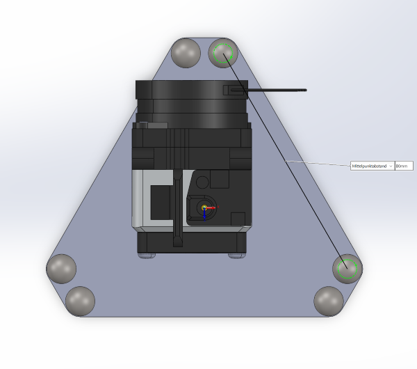
                      The rod spacing would have to bee at least 80mm to fit the RevoRoto.
                      Screenshot 2024-01-21 233624.png

                      dc42undefined T3P3Tonyundefined 2 Replies Last reply Reply Quote 0
                      • dc42undefined
                        dc42 administrators @MaxGyver
                        last edited by

                        @MaxGyver thanks for that. I wonder if even 80mm would be sufficient, because your diagram suggests that if the extruder is mounted that way then the motor would likely interfere with the rod to the top left ball.

                        Duet WiFi hardware designer and firmware engineer
                        Please do not ask me for Duet support via PM or email, use the forum
                        http://www.escher3d.com, https://miscsolutions.wordpress.com

                        1 Reply Last reply Reply Quote 0
                        • T3P3Tonyundefined
                          T3P3Tony administrators @MaxGyver
                          last edited by

                          @MaxGyver why would it not be rotated to be between the rods?

                          www.duet3d.com

                          czyzczyzundefined 1 Reply Last reply Reply Quote 0
                          • czyzczyzundefined
                            czyzczyz @T3P3Tony
                            last edited by

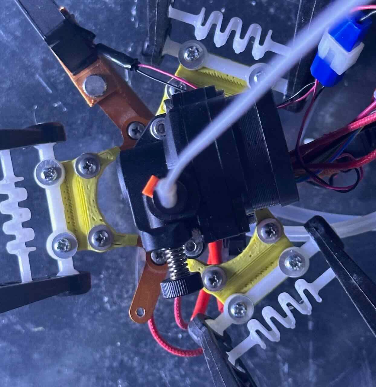
                            @T3P3Tony This is only semi-on-topic because I have a 713-maker effector plate on my Rostock Max v2, not a Smart Effector.

                            But I have cobbled together a real-world implementation of an LDO Orbiter V2.0 on that effector. My solution was to rotate (20º) and raise the extruder (25mm) to clear the arms. A short length of bowden tubing within the extender keeps the filament guided between motor and extruder. It turned out that this arrangement cut down on the build envelope more than desired (allowed the motor to hit the arms at the top extreme of the plate) so I moved all of the effector's arm attachment points outward by 13mm (increasing the size of the effector plate).

                            IMG_7509.jpeg
                            IMG_7507.jpeg

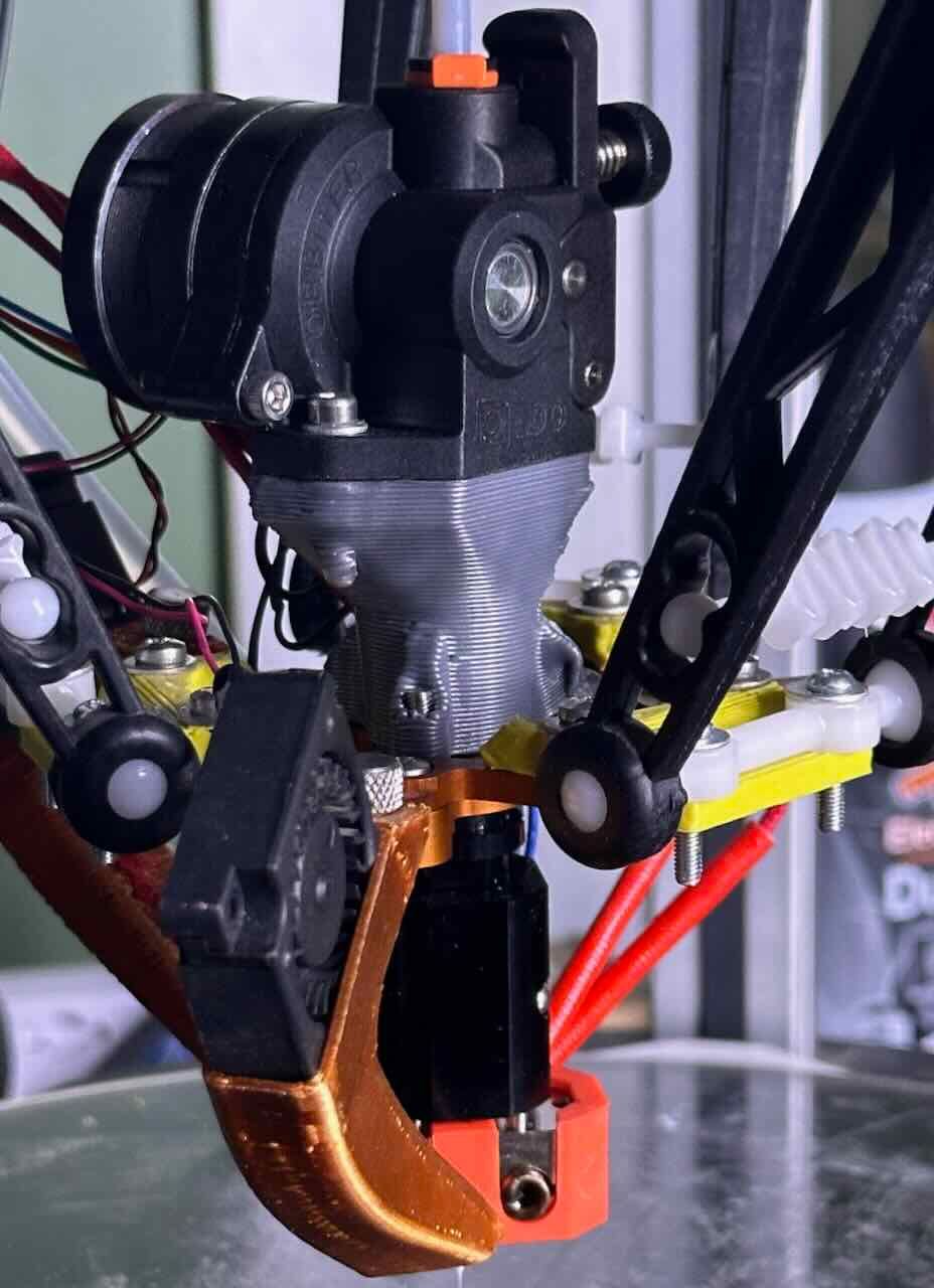
                            Raising and rotating the motor might have deleterious effects on momentum/vibration/tilt that outweigh the fact that it allows for a slightly smaller effector plate that still fits the motor between the arms. But it's working for me for the moment.

                            1 Reply Last reply Reply Quote 0
                            • HiWingundefined
                              HiWing
                              last edited by

                              Very keen to have something like this I have an Anycubic Predator, would like to use Orbiter 2.0 and maybe Pheatus Rapido, this is the same combo I run on my Large corexy 1100mm x 700mm x670mm running Duet 3 6hc, ready to order a smart delta effector as soon as they are ready to ship
                              Paul

                              1 Reply Last reply Reply Quote 0
                              • achrnundefined achrn referenced this topic
                              • First post
                                Last post
                              Unless otherwise noted, all forum content is licensed under CC-BY-SA