Duet3D Logo Duet3D
    • Tags
    • Documentation
    • Order
    • Register
    • Login

    6XD I/O >> Issue solved

    Scheduled Pinned Locked Moved
    Duet Hardware and wiring
    4
    121
    5.1k
    Loading More Posts
    • Oldest to Newest
    • Newest to Oldest
    • Most Votes
    Reply
    • Reply as topic
    Log in to reply
    This topic has been deleted. Only users with topic management privileges can see it.
    • tecnoundefined
      tecno @droftarts
      last edited by

      @droftarts

      Wires OK

      Same lonly LED

      Sanity check

      PXL_20240926_153206096.jpg PXL_20240926_153147366.jpg

      droftartsundefined 1 Reply Last reply Reply Quote 0
      • droftartsundefined
        droftarts administrators @tecno
        last edited by

        @tecno I've just tested it on a 6HC, on RRF 3.5.1, and it's working for a 7-segment LED strip. All light up correctly. The fix in 3.5.2 was if you were using IO ports for LEDs. I don't have a 6XD to test, but it should be exactly the same as 6HC.

        Can you send M115 and post the response?
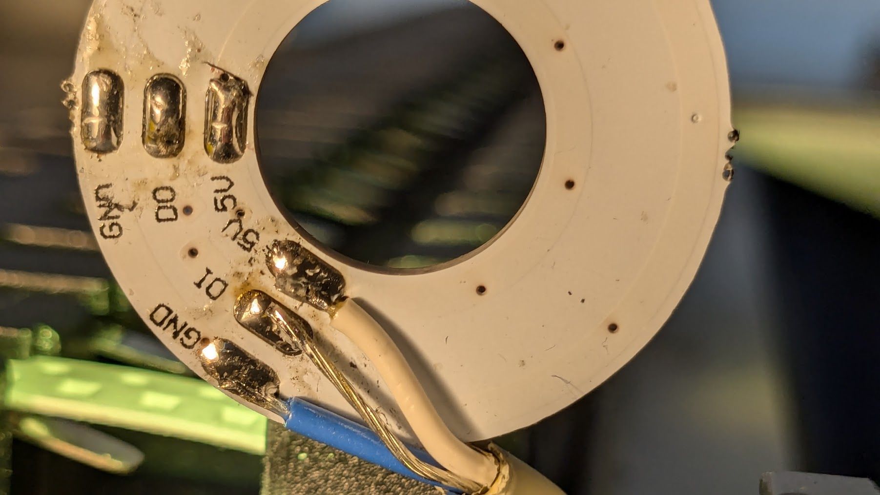
        Can you post a picture of the other side of the neopixel ring?
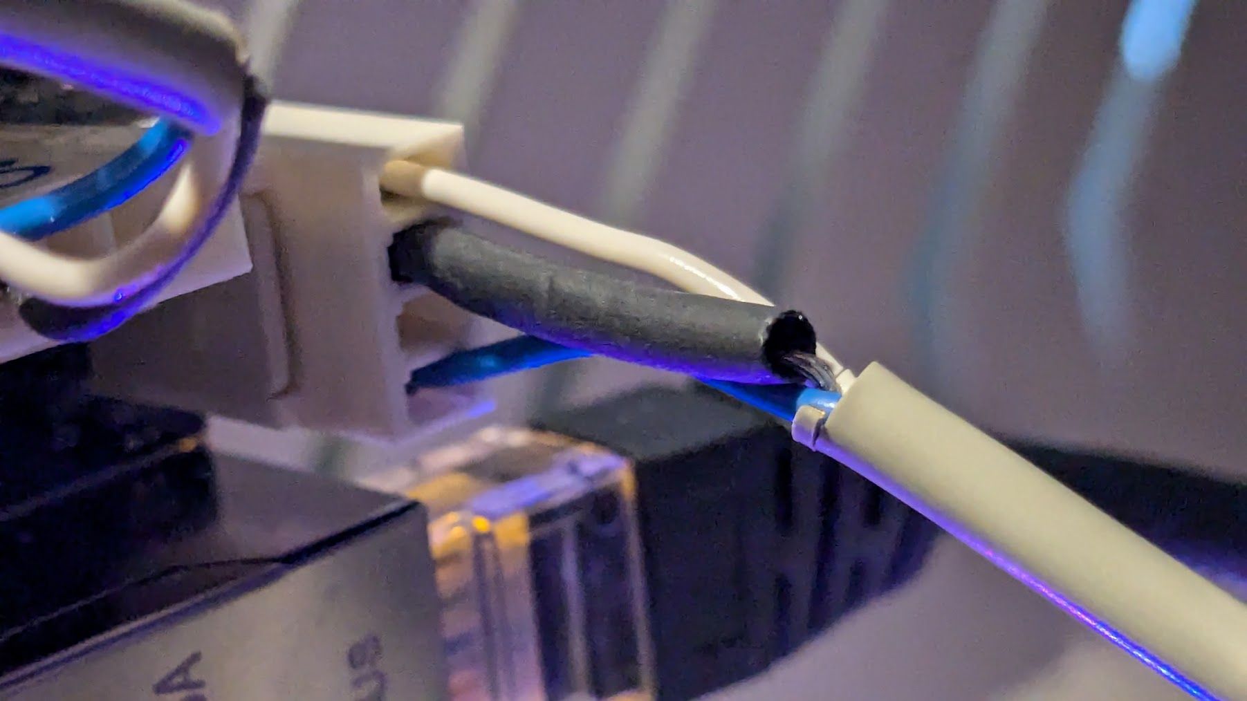
        Also, I'm not sure using the uninsulated wire as the high frequency data line is a good idea! Most likely it has higher resistance than a 'normal' wire, and may not be transmitting the signal effectively. Use a different wire.

        Ian

        Bed-slinger - Mini5+ WiFi/1LC | RRP Fisher v1 - D2 WiFi | Polargraph - D2 WiFi | TronXY X5S - 6HC/Roto | CNC router - 6HC | Tractus3D T1250 - D2 Eth

        tecnoundefined 1 Reply Last reply Reply Quote 0
        • tecnoundefined
          tecno @droftarts
          last edited by

          @droftarts

          m115
          FIRMWARE_NAME: RepRapFirmware for Duet 3 MB6XD FIRMWARE_VERSION: 3.5.3 ELECTRONICS: Duet 3 MB6XD v1.01 FIRMWARE_DATE: 2024-09-18 11:27:56

          PXL_20240926_160729457.jpg

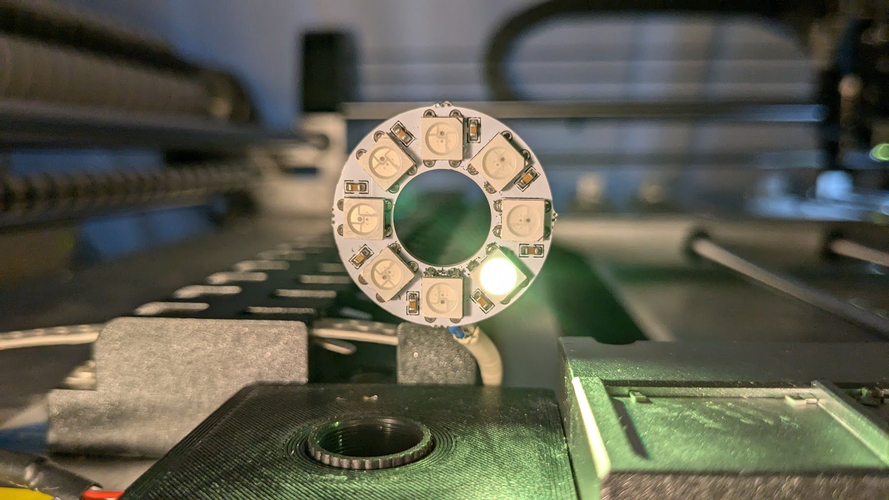
          This cable is a HQ Audio twisted pair with foil shield. Change White to shield.

          droftartsundefined 1 Reply Last reply Reply Quote 0
          • droftartsundefined
            droftarts administrators @tecno
            last edited by

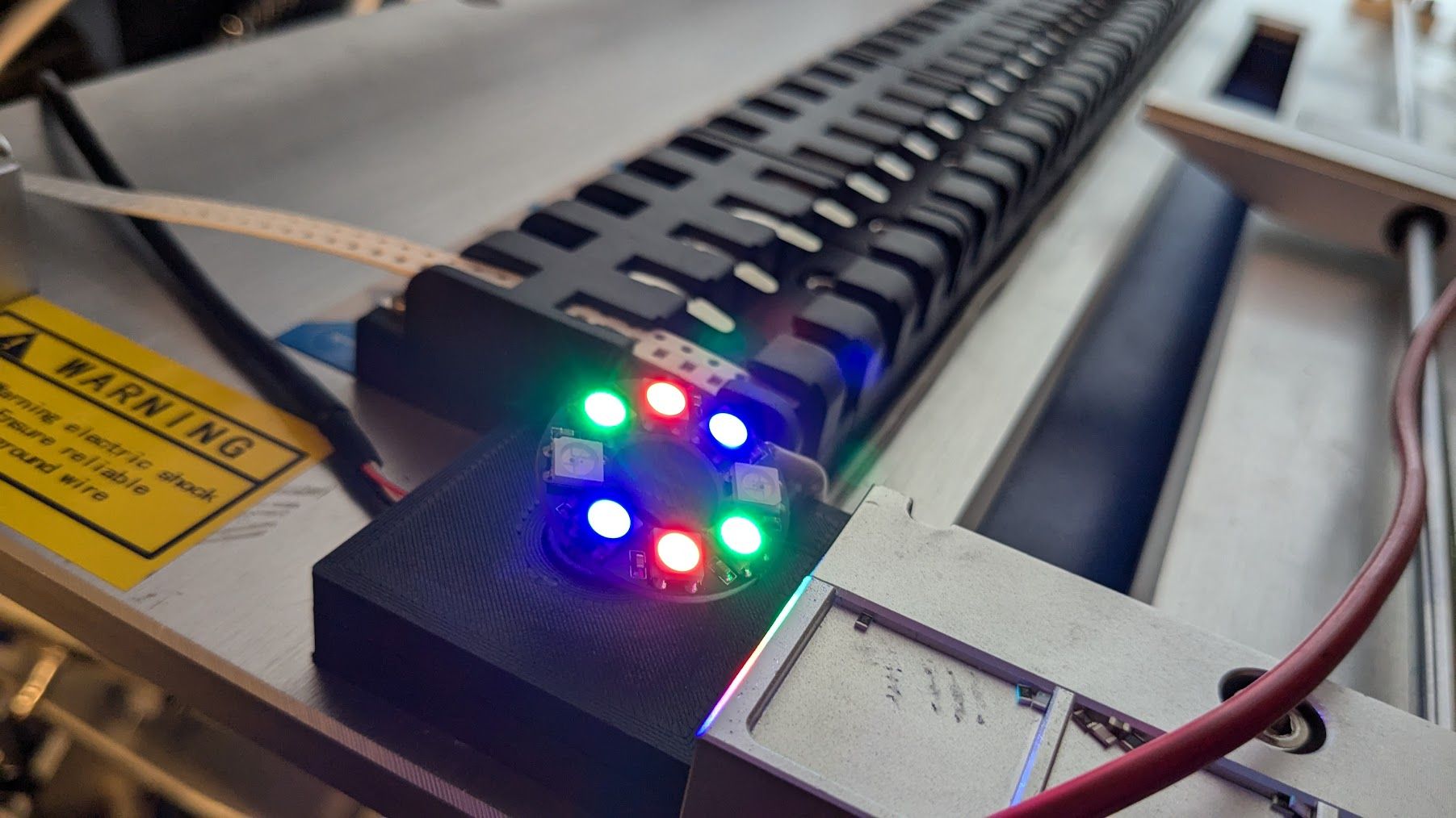
            @tecno Ah, that looks like an RGBW ring. Try

            M950 E0 C"led" Q3000000 T2
            M150 E0 R255 P128 S20 F0
            

            M950 T2 tells RRF that it's RGBW, not RGB.

            Ian

            Bed-slinger - Mini5+ WiFi/1LC | RRP Fisher v1 - D2 WiFi | Polargraph - D2 WiFi | TronXY X5S - 6HC/Roto | CNC router - 6HC | Tractus3D T1250 - D2 Eth

            tecnoundefined 1 Reply Last reply Reply Quote 0
            • tecnoundefined
              tecno @droftarts
              last edited by tecno

              @droftarts

              Same same

              Will change LED ring to one with black PCB board. This a job for torrow 😉

              tecnoundefined 1 Reply Last reply Reply Quote 0
              • tecnoundefined
                tecno @tecno
                last edited by

                @droftarts

                Morning Ian,

                Changed LED strip and only 1 of 8 is working on this one too.

                M950 E0 C"led" Q3000000 T2
                M150 E0 R255 P128 S20 F0

                Any suggestions?

                Cheers
                Bengt

                droftartsundefined 1 Reply Last reply Reply Quote 0
                • droftartsundefined
                  droftarts administrators @tecno
                  last edited by

                  @tecno I've just tested both RGB and RGBW LEDs on my 6HC, both worked without issue. I've asked someone with a 6XD to test.

                  Can you post a link to the white LED ring you bought? And post a picture of the current wiring?

                  Ian

                  Bed-slinger - Mini5+ WiFi/1LC | RRP Fisher v1 - D2 WiFi | Polargraph - D2 WiFi | TronXY X5S - 6HC/Roto | CNC router - 6HC | Tractus3D T1250 - D2 Eth

                  tecnoundefined 1 Reply Last reply Reply Quote 0
                  • tecnoundefined
                    tecno @droftarts
                    last edited by

                    @droftarts

                    https://vi.aliexpress.com/item/1005002313192735.html?spm=a2g0o.order_list.order_list_main.11.364b1802NFG3VP&gatewayAdapt=glo2vnm

                    Both white and ´blach PCB 8 LEDS

                    Wiring https://forum.duet3d.com/post/345489

                    gloomyandyundefined droftartsundefined 2 Replies Last reply Reply Quote 0
                    • gloomyandyundefined
                      gloomyandy @tecno
                      last edited by

                      @tecno Shouldn't the control signal be going to d0 and not to d1?

                      tecnoundefined 1 Reply Last reply Reply Quote 0
                      • tecnoundefined
                        tecno @gloomyandy
                        last edited by

                        @gloomyandy

                        As I understand is 6XD D0 out goes to Di in.

                        gloomyandyundefined 1 Reply Last reply Reply Quote 0
                        • droftartsundefined
                          droftarts administrators @tecno
                          last edited by droftarts

                          @tecno Those do look like RGB LEDs, looking closer. Though they should light up, just with the wrong colours, if you put the wrong T parameter in M950.

                          I thought you said you had changed the wire over? @tecno said in 6XD I/O >> Issue solved:

                          Change White to shield.

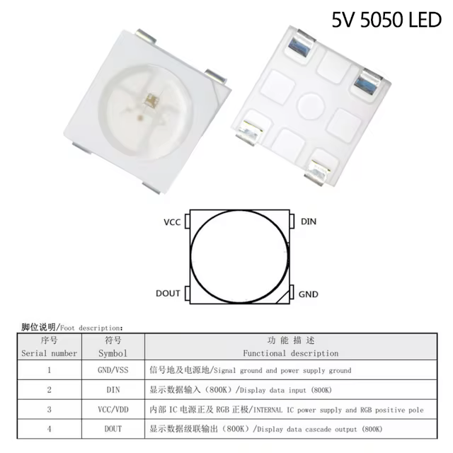
                          On each LED, there is a corner 'notch' to indicate which pin is GND. Can you check continuity of GND, DI and 5V from the LED pins to the connector?
                          7174cb7c-7d74-4af1-ad7f-e8ec910e7952-image.png

                          @gloomyandy It's DI for Digital In, DO is Digital Out, where it passes the signal on to the next one. Mine are labelled and wired like that.

                          Ian

                          Bed-slinger - Mini5+ WiFi/1LC | RRP Fisher v1 - D2 WiFi | Polargraph - D2 WiFi | TronXY X5S - 6HC/Roto | CNC router - 6HC | Tractus3D T1250 - D2 Eth

                          1 Reply Last reply Reply Quote 0
                          • gloomyandyundefined
                            gloomyandy @tecno
                            last edited by

                            @tecno This has nothing to do with the 6XD I'm talking about the pads on the LED ring, there is a D0 and a D1. Your wiring here: https://forum.duet3d.com/post/345489 shows it going to D1 I think it should go to D0. It seems very odd to me to have the input labelled D1 and the output labelled D0.

                            gloomyandyundefined 1 Reply Last reply Reply Quote 0
                            • gloomyandyundefined
                              gloomyandy @gloomyandy
                              last edited by

                              Ah yes that may be Din and Dout I suppose. Oh well good luck!

                              tecnoundefined 1 Reply Last reply Reply Quote 0
                              • tecnoundefined
                                tecno @gloomyandy
                                last edited by

                                @droftarts
                                So now I changed White to signal and Shield is now 5V

                                PXL_20240927_114529176.jpg

                                So now we are getting closer 🙂

                                droftartsundefined 1 Reply Last reply Reply Quote 0
                                • droftartsundefined
                                  droftarts administrators @tecno
                                  last edited by droftarts

                                  @tecno Okay, so now use:

                                  M950 E0 C"led" Q3000000 T1
                                  

                                  ie change T2 to T1

                                  I expect that bare 'earth' wire had too much capacitance to transmit the signal. Now you're using the bare wire for 5V, so easier to create a short. Same goes for using that wire for GND. I'd replace the wiring with individually insulated wires, ie 3-core wire. If you don't have 3-core wire, use left-over stepper motor wire, that's about the right gauge for LEDs.

                                  Ian

                                  Bed-slinger - Mini5+ WiFi/1LC | RRP Fisher v1 - D2 WiFi | Polargraph - D2 WiFi | TronXY X5S - 6HC/Roto | CNC router - 6HC | Tractus3D T1250 - D2 Eth

                                  tecnoundefined 1 Reply Last reply Reply Quote 0
                                  • tecnoundefined
                                    tecno @droftarts
                                    last edited by tecno

                                    @droftarts

                                    Works in R255 and P can be set = Nice.

                                    Now to play with new colors

                                    droftartsundefined 1 Reply Last reply Reply Quote 0
                                    • droftartsundefined
                                      droftarts administrators @tecno
                                      last edited by

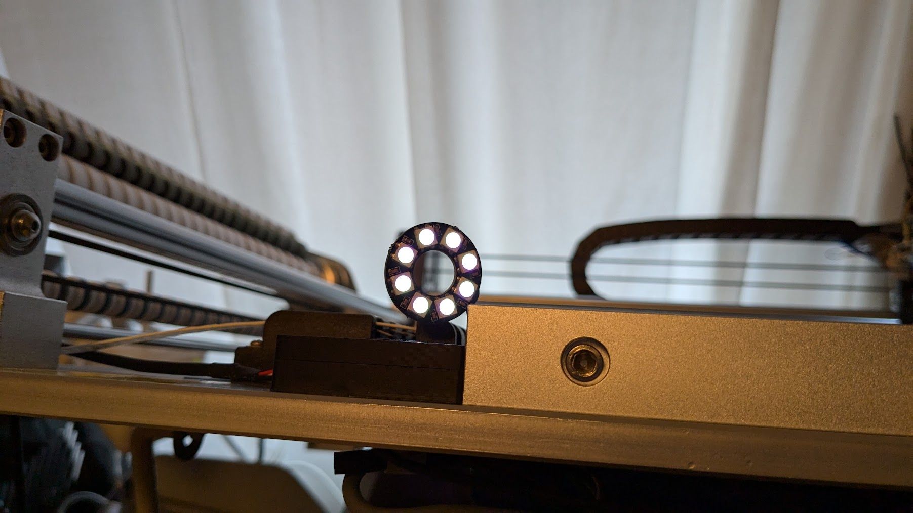
                                      @tecno Do all 8 LEDs work now, and are controllable?

                                      RGB LEDs aren't the best for white light. You'll have to play around with the levels in M150 for R, U (for green) and B, and brightness (P) to get close to what you want. If it's mostly white you want, you probably should have got RGBW, or just white, LEDs.

                                      Ian

                                      Bed-slinger - Mini5+ WiFi/1LC | RRP Fisher v1 - D2 WiFi | Polargraph - D2 WiFi | TronXY X5S - 6HC/Roto | CNC router - 6HC | Tractus3D T1250 - D2 Eth

                                      tecnoundefined 1 Reply Last reply Reply Quote 0
                                      • tecnoundefined
                                        tecno @droftarts
                                        last edited by

                                        @droftarts
                                        Yes all 8 work

                                        I am aware that I can not get perfect greyscale with RGB. Hard to find 8leds RGBW that fits.

                                        Thank you very much for your kind help Ian, I owe you a pint or two 🙂

                                        I am sure more questions will arise

                                        Cheers
                                        Bengt

                                        tecnoundefined 1 Reply Last reply Reply Quote 0
                                        • tecnoundefined
                                          tecno @tecno
                                          last edited by

                                          PXL_20240927_123456444.jpg

                                          1 Reply Last reply Reply Quote 2
                                          • tecnoundefined
                                            tecno @tecno
                                            last edited by tecno

                                            @droftarts

                                            @tecno said in 6XD I/O >> Issue solved:

                                            ;***Outputs
                                            M950 P0 C"out0" ; Q500 ;#1 Nozzle Vacuum
                                            M950 P1 C"out1" ; Q500 ;#2 Nozzle Vacuum
                                            M950 P2 C"out2" ; Q500 ;Drag PIN Actuator
                                            M950 P3 C"out3" ; Q500 ;ENA Nozzle 1/2 Up
                                            M950 P4 C"out4" ; Q500 ;Xross cursor
                                            M950 P5 C"out5" ; Q500 ;LED light x
                                            M950 P6 C"out6" ; Q500 ;Vacuum power

                                            Have problem with Outputs 4 and 5. can not switch off. Any advice is appreciated-

                                            Off=1.4V On=1.3V all other Off 24V On 0V

                                            tecnoundefined droftartsundefined 2 Replies Last reply Reply Quote 0
                                            • First post
                                              Last post
                                            Unless otherwise noted, all forum content is licensed under CC-BY-SA