Proof of Concept: The CoffeeMaker
-
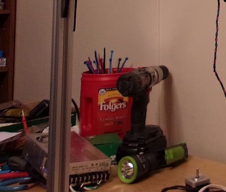
My ideas and my design of what I feel to be the most simple, uncluttered/uncomplicated clean and unique take on the Ultimaker style gantry. I humbly submit, The CoffeeMaker Concept.
VIDEO here... https://vimeo.com/274398226
Without even a tiny bit of tweaking, the movement of this concept is ROCK SOLID!


-
Interesting. What sort of bearings do you use in the carriage? Normal linear bearings are not designed for having the shaft rotate relative to the bearing. I wonder what would happen to print surface with motor vibrations coupled directly to the carriage through the rods.
-
I'm interested to see what happens. My guess is the bearings look like bronze bushings, which won't care about the rotation of the rod. If they are normal linear bearings, then he's gonna need to make a "rigid mount" to the frame of the stepper with a bearing on the backshaft of the motor.
How far are you from running it through it's paces?
-
User name checks out.

-
Interesting idea to link the steel rods to the motor shafts. As timothyz pointed out, bearings could become an issue. However, you could modify the couplers so that they have a regular radial bearing on the side that the couplers connect to the engine shaft and fix the coupler body to the motor body. This will eliminate the rotation of the steel guide rods, making them into "normal" linear moving rods only.
-
How did you get a Duet to be this noisy?
The design is wasting a lot of space on the XY plane, and not gaining much from it. And you move a lot of weight around for no real reason.
The couplers have to be 100% centered, and I doubt these are, as they are tightened from one side.
At least put the motors "outside" the moving area, so they "stick out" of the frame. This will increase your printable area around 10cm on both axes.
Lots of design issues IMHO
-
Here goes...
The bearings in the carriage are brass and graphite.
Honestly, holding a finger to the carriage while doing an air print, I could feel no more vibrations than on my Ulitmaker clone Creatbot.I'm probably going to keep this as a test bed and start another one with atleast a 400 x 300 build area. This one could do 280 x 280 but I never intended to complete it.
LMAO at Phaedrux !!!
I know that non rotating rods would be proper, but connected this way should keep the motors in sync and square.
It is dead silent compared to the over the top crappy drivers in my Creatbot.
The design is not wasting space. There was no previous assumption of how much it would have.
I don't know, I have not noted any vibrations or binding, so, the couplers seem to be centered.
If I put the motors on the outside, the frame would swing wildly about, it would be hello to fashion an enclosure for ABS printing and the output shafts would not be where they need to be. -
A fun little test... Video here: (3x normal speed) https://vimeo.com/275442255
I have a ton of parts coming and will begin in earnest, next week, building this machine's bigger better brother with an expected buld volume of ~ 440 x 340 x 300.
BTW, things like below are what I really enjoy working up and printing. Art does not have to be precise, only well received by the eye and keeps stress levels down over things like a print being off by a half mil. on an axis.


Cheers and stay tuned!
-
Nice build concept but make it really sense to raise the moving mass with about 600g per axis? ( aprox. 300g per steppermotor) doing a nice fast circle thats 1.2kg that have to be accelerated..sound that you have to use slow accelations. Is there any drawback if you put the motors stationary at the frame..like all other UM stlye printer?
I love my delta but if i ever build any cube style printr it would be a UM Style
-
If you do that maths, you'll find that mass isn't nearly the limiting factor that seems to have become ingrained in the 3D printing community. My Diamond hot ends mounted on two parallel X rails weighs in at around 1.8 Kgs that have to be moved in Y and I have demonstrated print speeds at up to 300mmsec. My 5 extruders are on a separate gantry, mounted above the hot end, which follows the hot end gantry and this assembly weighs in a 4.2 Kgs but is driven by it's own motors. The total mass is 6Kgs that have to moved in Y and my default non-print move speed is 350mm/sec, for which you need to run high accelerations.
-
@deckingman said in Proof of Concept: The CoffeeMaker:
If you do that maths, you'll find that mass isn't nearly the limiting factor that seems to have become ingrained
I miss a decision matrix and common document in the 3d community where the decision factors are aggregated. All those heatbed, mechanical construction, mass, direct drive vs bowden, belt vs wire discussions and no definite, physically (and economically, size etc.) proved scientific decisions. When I watch the hundreds of 3d constructions, my brain is trained to say "this printer has good stability, but heatbed awful" etc.
-
Most People would say, that a CR-10 is not a good design..moving the bed into Y and its get heavier with print time and size. and your design seems to even top it with 4.2kg. for me its the opposite what to use to get fast and exact printings..keep moving mass low. And thats physics. Sounds like you have the bumblebee of 3d printers..physics would say her wings are to small to fly properly..but it does
Your non printing moves could be at mach1...doesnt matter except the wear on the mechanic would be bigger...but how good and fast can you print 90° corners? Won´t the nozzle overshoot it?
Till i saw your design i thought the next lightweight concept after a Delta is the UM style
-
The 4 kg is only possible because you have a stable construction which supports it. If you need a light printer to be portable, you would have mass constraints. It all depends on those requirements of quality, cost, weight ...
-
Wow. Does no one have any fun with 3D printing/printers, everything has to be really technical?
-
@coffee I bet they would love the deltesian.
https://bornity.com/deltesian-hybrid-3d-printer-large-format-print-test-jan-4-2018/
-
I don't care what it's slingin', that sucker is fun to watch!
-
@ Coffee
Of course I have fun - much of it is doing what people say you should not - don't worry about the mass, just do it.@ Joergs. A suitcase is portable and might weigh 20 to 30 kgs so.... My printer is sort of portable, it weighs a lot less than 20kgs in total - just need a big van.

@ Barracuda. Of course I can do 90 degree corners. Why would the print head overshoot? - that's a function of rigidity, not just mass.
Yes, of course it's physics and reducing the moving mass is a sound principle but only within limits. Once you reach the lower limit of practical mass for the speeds and acceleration desired or which are otherwise attainable , there is no point in reducing it further.
Like I said, do the maths. A very conservative calculation of the torque that my steppers can produce tells me that I can accelerate my 4kg mass at 1400 mm/sec^2. With my print bed size of 360mm, then in theory I could reach a speed of a tad over 700mm/sec. Reducing the mass would allow me to accelerate at a higher rate and reach an even higher speed but why would I want to move faster than 700mm/sec?
Or put another way, to reach a print speed of 100mm/sec (which is faster than most people use) at an acceleration of 1400mm/sec that speed is reached in 0.071 sec and it takes 3.57mm of movement to attain that speed. Halving the mass to 2kgs would halve those numbers to 0.035 secs and 1.8mm, halving it again to 1 kg brings the numbers down to 0.017 secs and 0.9mm. So we quickly reach a limit of diminishing returns IMO at anything below about 1kg .
Of course there are gains to be had by reducing the mass further but my point is that those gains aren't as big as most people think they are - especially when you look at the difference between say 300gms and 200gms. You are very unlikely to be able to make use of the extra acceleration that the reduced mass makes possible. Maybe on a Delta it's a necessary consideration because of the way they are constructed but if you build a rigid frame, high moving mass is not such a big deal as most people think.
-
Hi @coffee,
I'm with @deckingman. Theory is great and everyone has an opinion about this or that, but there's no substitute to actually building and testing things out in reality. So keep it up!
")
Also, I wanted to ask if you would mind sharing your config.g? I'm curious as to how you mapped the drivers to run each pair of steppers.
-
@snowcrash I appreciate those words and that is the way I feel toward others and their undertakings as well!
The stepper pairs are just wired in series and out of phase, with one pair connected to the X driver and the other pair connected to the Y driver, using splitter adapters I made up from some extension cables I had sitting around.
Below is this project's stepper wiring diagram.
-
Thanks for the info and diagram, @coffee!
In terms of connecting the steppers in series, is there an advantage to hooking them up like you did as opposed to this setup:
