• Tags
  • Documentation
  • Order
  • Register
  • Login
Duet3D Logo Duet3D
  • Tags
  • Documentation
  • Order
  • Register
  • Login

Best lead screw - ball bearing mount system

Scheduled Pinned Locked Moved
3D Printing General Chat
13
42
5.2k
Loading More Posts
  • Oldest to Newest
  • Newest to Oldest
  • Most Votes
Reply
  • Reply as topic
Log in to reply
This topic has been deleted. Only users with topic management privileges can see it.
  • undefined
    claustro @mrehorstdmd
    last edited by 1 Jun 2019, 16:15

    @mrehorstdmd
    is something like this enough "bulky"?

    0_1559405728244_lead screw mount 2 v2.jpg

    1 Reply Last reply Reply Quote 0
    • undefined
      mrehorstdmd
      last edited by 1 Jun 2019, 16:40

      Yes, I'd do something like that. I'd also use modifier meshes to increase the fill density around the mounting bolt holes.

      https://drmrehorst.blogspot.com/

      1 Reply Last reply Reply Quote 0
      • undefined
        Veti
        last edited by 1 Jun 2019, 16:41

        that reminds me there was a video by alex kenis about this
        https://www.youtube.com/watch?v=2Z7mZVvPlc8

        1 Reply Last reply Reply Quote 0
        • undefined
          claustro
          last edited by 3 Jun 2019, 19:03

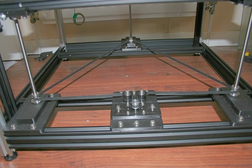
          While I am trying to fix the squareness of the frame I finalized!the Z axis belt system
          This is what it came out.
          I tried to make the belt running as much as possible around the pulley with this setup all the pulley has 180 degree belt contact.
          The 2 tensioners are temporary , I am going to print a support for it
          Any suggestion will be appreciated.
          Thank you
          Andrea
          0_1559588633233_20190603_173238 (Medium).jpg

          undefined undefined 2 Replies Last reply 3 Jun 2019, 19:09 Reply Quote 1
          • undefined
            deckingman @claustro
            last edited by 3 Jun 2019, 19:09

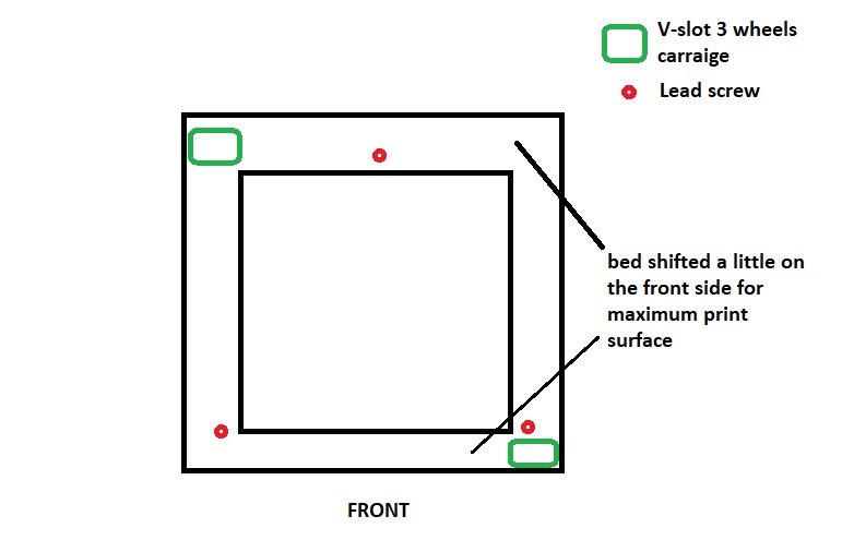
            @claustro How come those front two lead screws are set so far back from the front of the frame?

            Ian
            https://somei3deas.wordpress.com/
            https://www.youtube.com/@deckingman

            undefined 1 Reply Last reply 3 Jun 2019, 19:14 Reply Quote 0
            • undefined
              claustro @deckingman
              last edited by 3 Jun 2019, 19:14

              @deckingman this is only a temporary disposition , at the end the 2 front lead screw will be as far as possible from the back one

              undefined 1 Reply Last reply 3 Jun 2019, 19:23 Reply Quote 0
              • undefined
                deckingman @claustro
                last edited by 3 Jun 2019, 19:23

                @claustro said in Best lead screw - ball bearing mount system:

                @deckingman this is only a temporary disposition , at the end the 2 front lead screw will be as far as possible from the back one

                Ah OK. I was a bit concerned that the two side rails might flex due to the weight of the bed acting so far away from the end fixings. Those "Tee plates" might flex though. If you can, check for any deflection by using a dial gauge if you can lay your hands on one, and adding a weight to simulate the weight of the bed to the top of the lead screw couplings.

                Ian
                https://somei3deas.wordpress.com/
                https://www.youtube.com/@deckingman

                undefined 1 Reply Last reply 3 Jun 2019, 20:37 Reply Quote 0
                • undefined
                  claustro @deckingman
                  last edited by 3 Jun 2019, 20:37

                  @deckingman

                  I am trying to use your Z rail configuration with only 2 carriage in a diagonal disposition .
                  If you talking about the plastic tee plate , the one that fix the 2020 that support the 2 front lead screws, I am going to switch to aluminum one as soon I 'll have my CNC running . ( it will be my first easy test with aluminum 🙂 )

                  I have a dial gauge and I surely check what you suggest.

                  0_1559593583822_Immagine.jpg

                  undefined 1 Reply Last reply 3 Jun 2019, 21:27 Reply Quote 0
                  • undefined
                    deckingman @claustro
                    last edited by 3 Jun 2019, 21:27

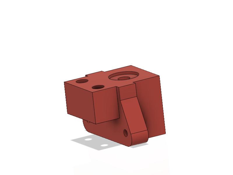
                    @claustro For info, here is how I mounted my lead screw blocks.

                    0_1559597136362_ZAxisCompleteSmall.jpg

                    So each block is supported on two 2020 extrusions. One might be OK but check for deflection.

                    Ian
                    https://somei3deas.wordpress.com/
                    https://www.youtube.com/@deckingman

                    1 Reply Last reply Reply Quote 0
                    • undefined
                      claustro
                      last edited by 3 Jun 2019, 21:42

                      I have 2 spare 2040 peaces I can always copy your design in case I'll find some flex

                      1 Reply Last reply Reply Quote 0
                      • undefined
                        claustro
                        last edited by 13 Jun 2019, 08:43

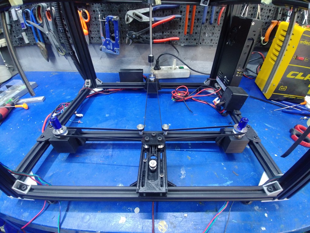
                        I changed the setup following your tips this is the result.
                        Now I have to choose if make a bed leveled by lead screws or by another set of screws only for the bed.

                        0_1560415418410_20190611_184108 (Small).jpg

                        undefined 1 Reply Last reply 13 Jun 2019, 11:49 Reply Quote 0
                        • undefined
                          deckingman @claustro
                          last edited by 13 Jun 2019, 11:49

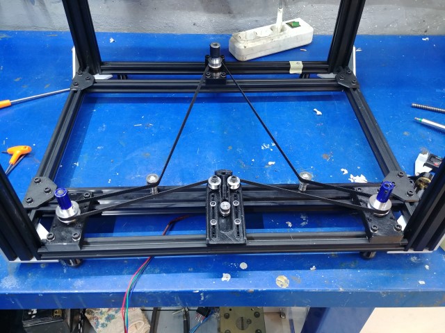
                          @claustro That looks very familiar ☺

                          Ian
                          https://somei3deas.wordpress.com/
                          https://www.youtube.com/@deckingman

                          undefined 1 Reply Last reply 13 Jun 2019, 21:27 Reply Quote 0
                          • undefined
                            claustro @deckingman
                            last edited by 13 Jun 2019, 21:27

                            @deckingman eh eh 🙂

                            1 Reply Last reply Reply Quote 0
                            • undefined
                              claustro
                              last edited by 17 Jun 2019, 08:23

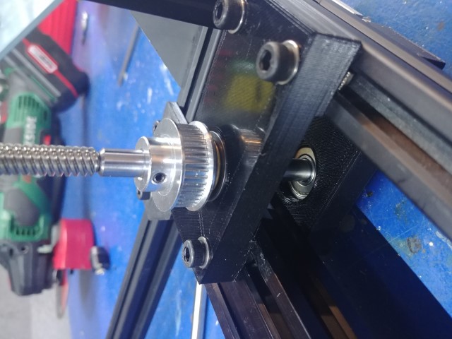
                              I am thinking to change my setup.
                              with only one bearing when I tension the belt the shaft tend to be dragged towards the centre, creating tension on the lead screw, for this reason I am making another support for another ball bearing under the previous one fixed on the other side of the vslot. The 4cm distance between the 2 bearing should improve the stiffness of the system.

                              1 Reply Last reply Reply Quote 0
                              • undefined
                                claustro
                                last edited by 17 Jun 2019, 17:25

                                this is what I did
                                0_1560792326047_20190617_191558 (Piccola).jpg

                                1 Reply Last reply Reply Quote 0
                                • undefined
                                  bondus
                                  last edited by bondus 17 Jun 2019, 20:27

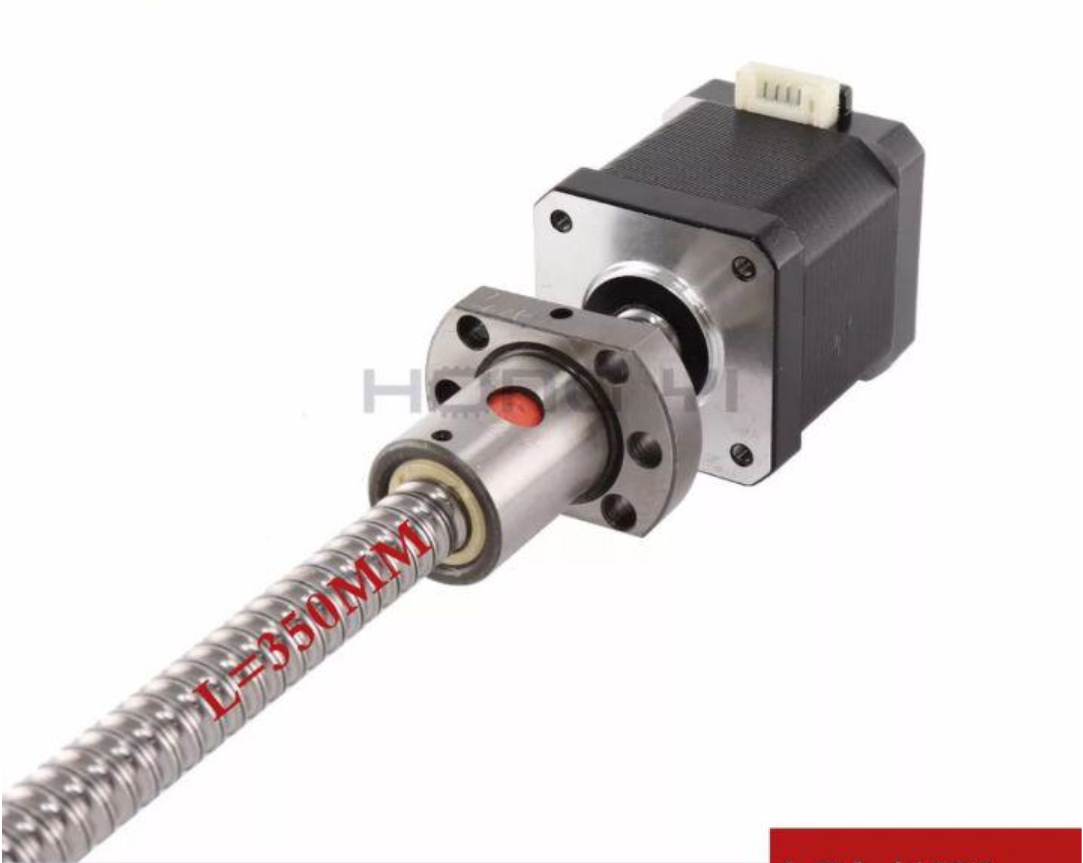
                                  I have had issues with the z-axis due to that the 8mm hole on the pulleys are slightly oversized. Advertised 8mm, real world 8.07mm. And the lead screws tend to be slightly undersized, typically 7.9mm. This may lead to that the pulley is mounted at a slight angle causing massive z-banding. With an 8mm pitch screw it is not very visible, but with a 1.5mm pitch screw it certainly is.

                                  The nice screw @claustro has should solve that problem. Where did you find such a screw?
                                  My goto screw-peddler offers them with a machined 5mm end, I'm very tempted to get one of those.

                                  @sinned6915 said in Best lead screw - ball bearing mount system:

                                  Proper design would be to use a pair of angular contact bearings that bear on a shoulder, but those are $$$

                                  0_1560801837598_AngularBearing.jpg
                                  $5 a piece on ali, seems to be good quality. A bit scary with an open bearing.

                                  Edit: Typo

                                  1 Reply Last reply Reply Quote 0
                                  • undefined
                                    sinned6915
                                    last edited by sinned6915 18 Jun 2019, 03:52

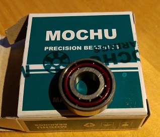
                                    @bondus - what bearing is that? you have piqued my curiosity.
                                    looking at my printer now, i realize that i might have left out and important bit- i used a shaft collar on there too between the pulley and the thrust bearing-
                                    https://www.mcmaster.com/6655k54
                                    and i think
                                    https://www.mcmaster.com/6157k32

                                    1 Reply Last reply Reply Quote 0
                                    • undefined
                                      bondus
                                      last edited by 18 Jun 2019, 14:25

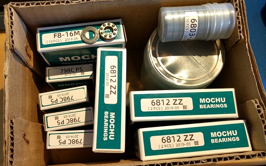
                                      @sinned6915. Clamping shaft collar, should get a straighter clamp than with a set screw, I need to get some of those.

                                      The bearing is a 798C, 15 degree angle bearing. Mochu has their own shop on ali, lots of specialized bearings. I have bought many bearings from them, they are good.
                                      0_1560867899433_IMG_20190618_160007793_HDR - Copy.jpg

                                      1 Reply Last reply Reply Quote 0
                                      • undefined
                                        Denis
                                        last edited by 18 Jun 2019, 15:57

                                        I got the best results with this solution (assuming that the Chinese friends inserting the axis exactly) 0_1560873439748_2019-06-18_18-54-56.png

                                        undefined 1 Reply Last reply 18 Jun 2019, 16:51 Reply Quote 0
                                        • undefined
                                          Veti @Denis
                                          last edited by 18 Jun 2019, 16:51

                                          yes the sfu1204 are working nicely on my printer as well.
                                          no play and very rid-git. you might even be able to use them without linear guides.

                                          1 Reply Last reply Reply Quote 0
                                          • First post
                                            Last post
                                          Unless otherwise noted, all forum content is licensed under CC-BY-SA