Duet3D Logo Duet3D
    • Tags
    • Documentation
    • Order
    • Register
    • Login

    12864 display (ST7920) on Duet 3 Mini5+

    Scheduled Pinned Locked Moved
    Duet Hardware and wiring
    10
    31
    3.6k
    Loading More Posts
    • Oldest to Newest
    • Newest to Oldest
    • Most Votes
    Reply
    • Reply as topic
    Log in to reply
    This topic has been deleted. Only users with topic management privileges can see it.
    • DIY-O-Sphereundefined
      DIY-O-Sphere
      last edited by DIY-O-Sphere

      I have connected a level shifter to the Duet Mini+.
      In principle, the display works, the printer can be operated, but there may be an error in my circuit since strange artefacts are visible.

      40215990-d5de-454e-ab88-dcdf7098b457-grafik.png
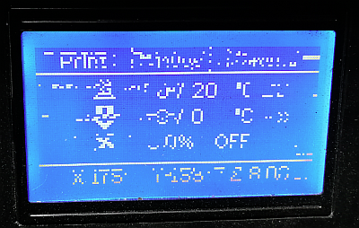
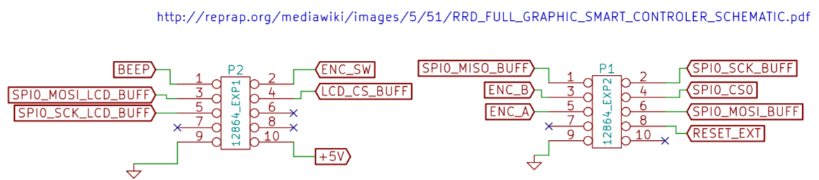
      I have orientated myself on this.
      But it took some time to work through the thread, because it ends up being a mishmash of different firmware, boards and lcd types.

      I tried to create a mapping table between the maestro and the mini, because the display ran perfectly on the maestro before.
      Since the names and functions of the pins are differently, it was difficult to create the circuit diagram.
      The pins that I could not clearly assign are marked in red. This is where I suspect the issue.
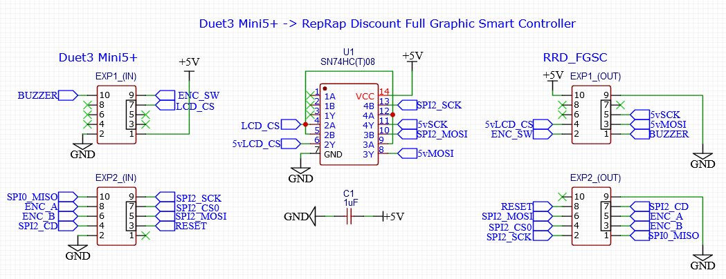
      e3d5974f-6395-4520-ac87-f36acc1431e4-grafik.png

      Edit:
      Wiring schematic updated to the fully functional revision

      (UTC+1)

      DIY-O-Sphereundefined 1 Reply Last reply Reply Quote 0
      • DIY-O-Sphereundefined
        DIY-O-Sphere @DIY-O-Sphere
        last edited by DIY-O-Sphere

        I now have reduced the frequence in M918 and the artefacts are gone.
        Does that mean that the shifting isn't working?

        (UTC+1)

        pixelpieperundefined 1 Reply Last reply Reply Quote 0
        • pixelpieperundefined
          pixelpieper @DIY-O-Sphere
          last edited by

          @diy-o-sphere it just means that your level shifting circuit isn’t fast enough for stable operation. If it works with the reduced frequency you are fine.

          Voron V2.434 / Duet 3 Mini5+, Duet 3 Expansion Mini 2+, Duet 1LC V1.1 Toolboard
          Voron V0.250 / Duet 2 Maestro

          DIY-O-Sphereundefined 1 Reply Last reply Reply Quote 0
          • DIY-O-Sphereundefined
            DIY-O-Sphere @pixelpieper
            last edited by

            @pixelpieper
            Reducing 1Hz does the trick...πŸ‘
            M918 P1 E-4 F1999999 works....

            (UTC+1)

            pixelpieperundefined alankilianundefined 2 Replies Last reply Reply Quote 0
            • pixelpieperundefined
              pixelpieper @DIY-O-Sphere
              last edited by

              @diy-o-sphere I would change it by more - maybe half the default. Otherwise this might break again with small environmental changes in temperature or humidity or just over time...

              Voron V2.434 / Duet 3 Mini5+, Duet 3 Expansion Mini 2+, Duet 1LC V1.1 Toolboard
              Voron V0.250 / Duet 2 Maestro

              1 Reply Last reply Reply Quote 2
              • alankilianundefined
                alankilian @DIY-O-Sphere
                last edited by

                @diy-o-sphere Do you have the data sheet for your LCD module?

                I looked at several and found the maximum SPI clock to be between 800,000 Hz and 2,500,000 Hz so it looks like the modules are quite different from one another.

                SeemeCNC Rostock Max V3 converted to V3.2 with a Duet2 Ethernet Firmware 3.2 and SE300

                DIY-O-Sphereundefined 1 Reply Last reply Reply Quote 0
                • DIY-O-Sphereundefined
                  DIY-O-Sphere @alankilian
                  last edited by

                  @alankilian
                  No. It is a cheap clone which I had bought when I had started with the Ramps,
                  But it worked propper for years on the Maestro (2Mhz)
                  The circuit is still sitting on the breadboard, the "cable spaghetti" is certainly not very helpful.

                  (UTC+1)

                  DIY-O-Sphereundefined 1 Reply Last reply Reply Quote 0
                  • DIY-O-Sphereundefined
                    DIY-O-Sphere @DIY-O-Sphere
                    last edited by

                    @dc42
                    Can you please take a short look at the wiring diagram?
                    The LCD works fine now, but I can't get the SD card reader to work.
                    My best guess is, it has someting to do with SPI2_CS0 on the output.
                    I already tried connecting to SPI2_CD and SPI2_CS3, but no success.
                    (I don't use the external SD Card, but I would like to have the wiring right.)

                    (UTC+1)

                    dc42undefined 1 Reply Last reply Reply Quote 0
                    • dc42undefined
                      dc42 administrators @DIY-O-Sphere
                      last edited by dc42

                      @DIY-O-Sphere, are you really saying that the LCD works if you use F1999999 in the M918 command, but not if you use F2000000 ? That sounds most unlikely.

                      Three comments:

                      1. The level shifter IC should be 74HCT08, not 74HC08.
                      2. You should ground the unused 1A and 1B inputs of the 74HCT08, or connect them to +5V.
                      3. The Duet 3 Mini has a card detect input, SPI2_CD in your diagram. You should connect that to the card detect output of your LCD if it has one. It's probably EXP2 pin 7 on your LCD. Caution, you must not apply 5V to SPI2_CD. So check that EXP2 pin 7 is connected to ground when the SD card is inserted, and is floating when it is not. If the LCD doesn't support the card detect output, ground the SPI2_CD pin instead.

                      HTH David

                      Duet WiFi hardware designer and firmware engineer
                      Please do not ask me for Duet support via PM or email, use the forum
                      http://www.escher3d.com, https://miscsolutions.wordpress.com

                      DIY-O-Sphereundefined 1 Reply Last reply Reply Quote 0
                      • DIY-O-Sphereundefined
                        DIY-O-Sphere @dc42
                        last edited by

                        @dc42 said in 12864 display (ST7920) on Duet 3 Mini5+:

                        The level shifter IC should be 74HCT08, not 74HC08.

                        It's a typo IC is 74HCT08

                        You should ground the unused 1A and 1B inputs of the 74HCT08, or connect them to +5V.

                        I will do this later in a soldered pcb board

                        The Duet 3 Mini has a card detect input, SPI2_CD in your diagram. You should connect ............

                        782439d4-5201-4fa9-bf77-b8454ad82495-grafik.png

                        You are briliant
                        It is not shown in the diagram but it is present. (The Maestro didn't have the connector).
                        When the card is inserted it changes from 0.4V to 0V. I think that should be fine.
                        I have currently connected SPI2_CD to ground and it works.
                        Thanks a lot.

                        I still have one final question.
                        I have an accelerometer that I want to connect to the PanelDue connector.
                        b8390d27-ae24-4740-83af-0a849ee55e9e-grafik.png
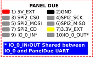
                        Will this work in combination with the LCD sd card reader (same SPI bus)?
                        I will not run both at the same time.

                        (UTC+1)

                        dc42undefined 1 Reply Last reply Reply Quote 0
                        • dc42undefined
                          dc42 administrators @DIY-O-Sphere
                          last edited by dc42

                          @diy-o-sphere the accelerometer is normally connected to the temperature daughter board connector. I think it should be possible to use the PanelDue connector instead, but I haven't tested that. It should work OK with the LCD card reader if the cables are short.

                          Duet WiFi hardware designer and firmware engineer
                          Please do not ask me for Duet support via PM or email, use the forum
                          http://www.escher3d.com, https://miscsolutions.wordpress.com

                          DIY-O-Sphereundefined 1 Reply Last reply Reply Quote 0
                          • DIY-O-Sphereundefined
                            DIY-O-Sphere @dc42
                            last edited by

                            @dc42

                            the accelerometer is normally connected to the temperature daughter board connector.

                            My pIan was, that by using IO.0 only one plug is required.
                            But it's just to play around.
                            I will buy the new toolboard as soon as it is available here.
                            Thanks for the announcementπŸ‘
                            I don't feel disadvantaged, quite the opposite.

                            (UTC+1)

                            1 Reply Last reply Reply Quote 0
                            • PCRundefined
                              PCR
                              last edited by

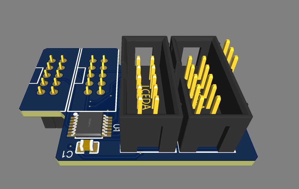
                              Hello i am in the process of making a small Production run based on @DIY-O-Sphere schematic. IT will be Board which will be directly olugged Into the Mini;)
                              Please upvote If you want one!

                              PCRundefined 1 Reply Last reply Reply Quote 6
                              • PCRundefined
                                PCR @PCR
                                last edited by

                                @pcr

                                7127750a-6cba-4566-904d-cb953a1097cb-grafik.png

                                7c3b49b7-9907-4405-b353-81a89670e9d4-grafik.png

                                PCRundefined kgolgerundefined 2 Replies Last reply Reply Quote 3
                                • PCRundefined
                                  PCR @PCR
                                  last edited by PCR

                                  @pcr

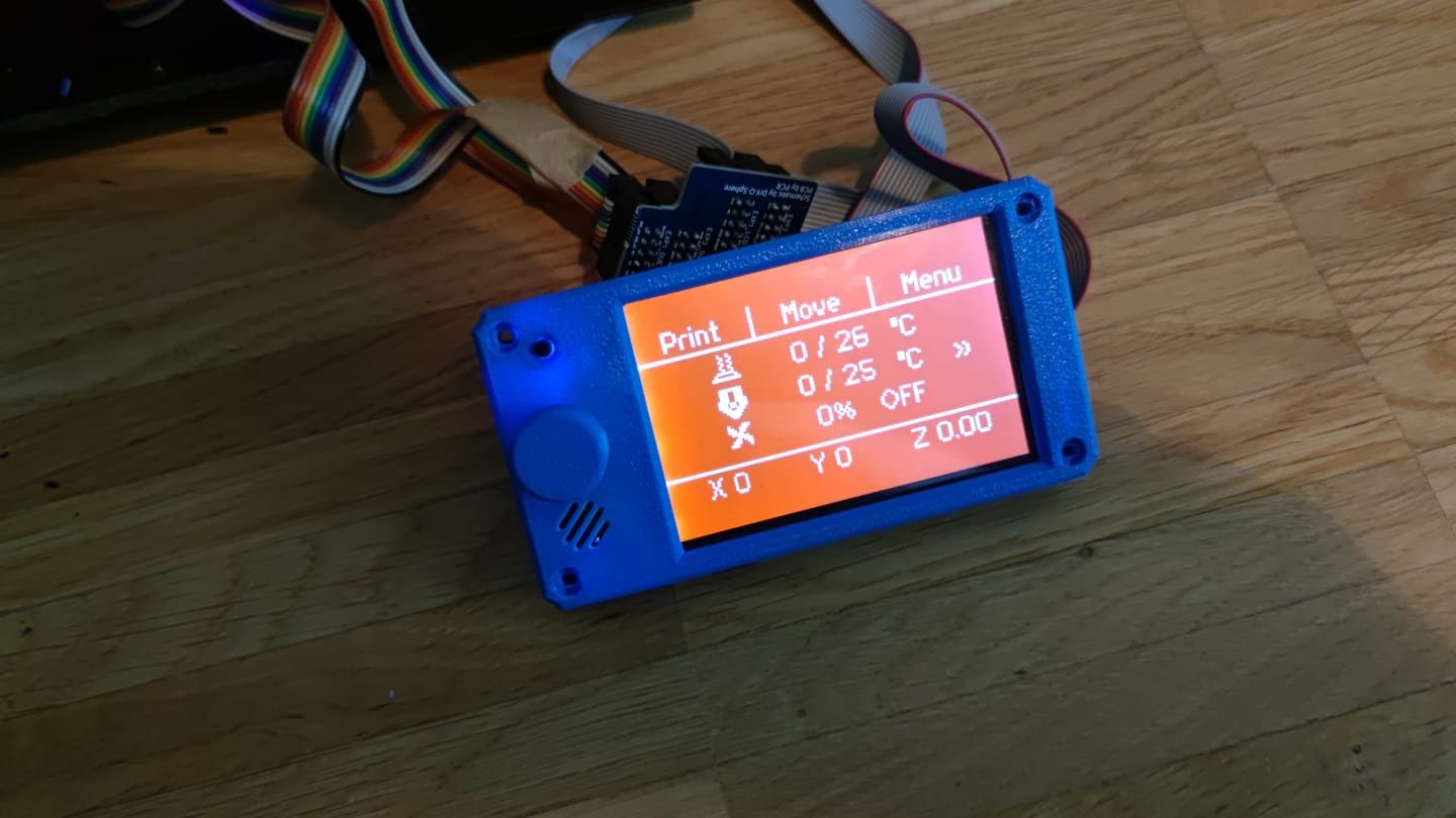
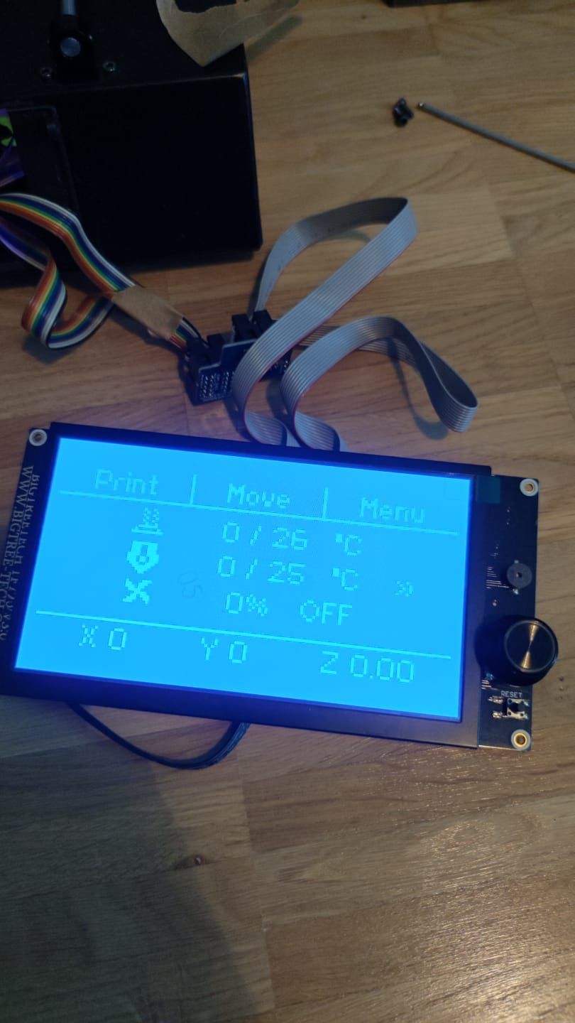
                                  The adapters are here and they work. I tested it with the classic Display, the BTT 35 and the BTT 70.

                                  Please PN if you want one! You can choose between a plugin type or a "extension" one πŸ˜‰ For plugin see the image above

                                  WhatsApp Image 2021-07-05 at 10.41.58.jpeg WhatsApp Image 2021-07-05 at 10.41.584.jpeg WhatsApp Image 2021-07-05 at 10.41.585.jpeg

                                  MatixYoundefined 1 Reply Last reply Reply Quote 3
                                  • MatixYoundefined
                                    MatixYo @PCR
                                    last edited by

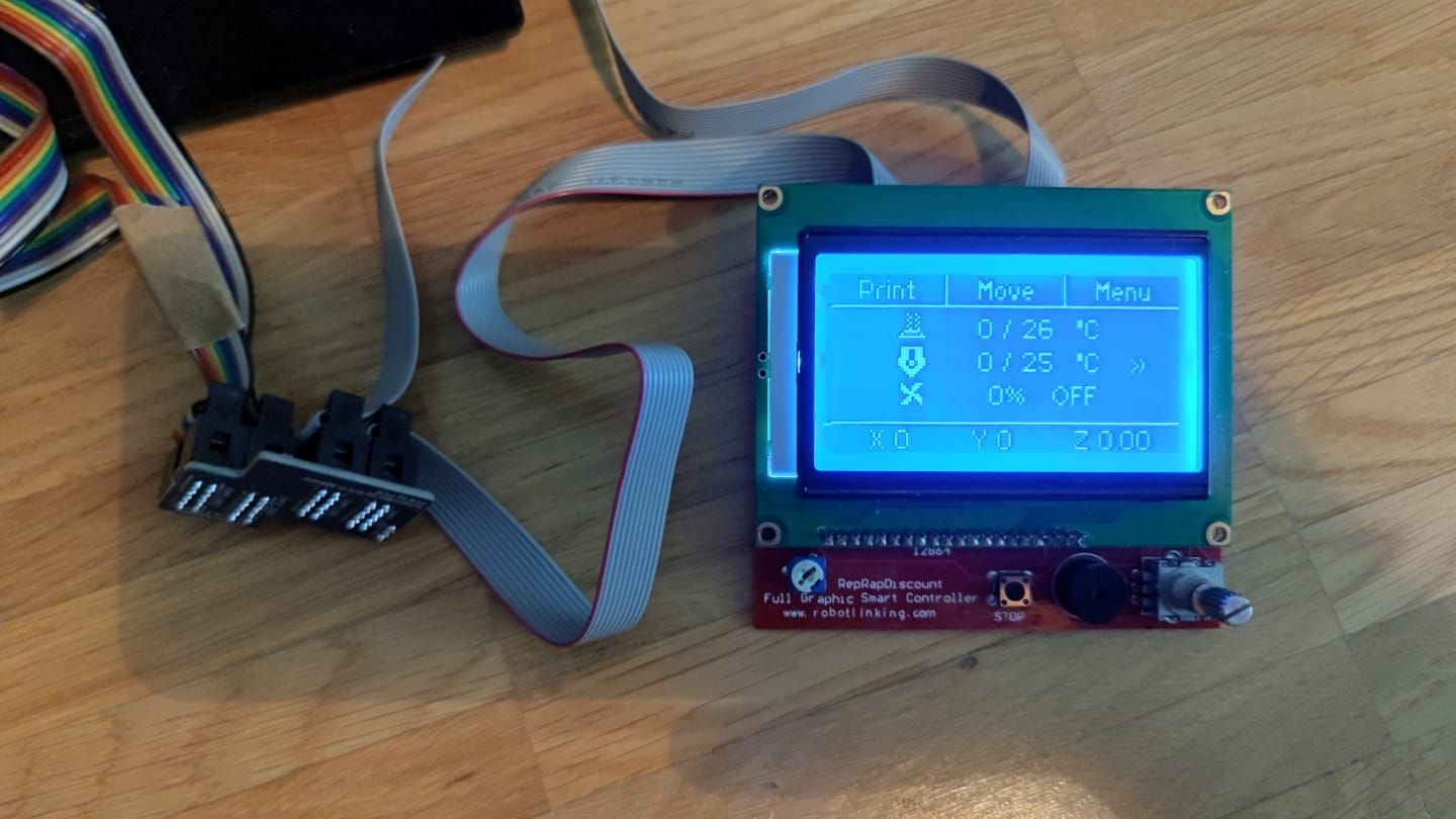
                                    @pcr how much is it?

                                    PCRundefined 1 Reply Last reply Reply Quote 0
                                    • PCRundefined
                                      PCR @MatixYo
                                      last edited by

                                      @matixyo

                                      6€ with connectors.

                                      4€ untracked shipping. 7€ tracked

                                      MatixYoundefined Giannivoxundefined 2 Replies Last reply Reply Quote 0
                                      • MatixYoundefined
                                        MatixYo @PCR
                                        last edited by

                                        @pcr not bad

                                        1 Reply Last reply Reply Quote 0
                                        • Giannivoxundefined
                                          Giannivox @PCR
                                          last edited by

                                          @pcr Hi, adapters in compatible with mks mini12864 v2.1?
                                          thanks

                                          DIY-O-Sphereundefined 1 Reply Last reply Reply Quote 1
                                          • DIY-O-Sphereundefined
                                            DIY-O-Sphere @Giannivox
                                            last edited by

                                            @giannivox
                                            If the LCD has a ST7567 chip, the adapter is not required.

                                            (UTC+1)

                                            1 Reply Last reply Reply Quote 1
                                            • First post
                                              Last post
                                            Unless otherwise noted, all forum content is licensed under CC-BY-SA