Sovol SV08 Multiple Motion System Upgrade.
-
Quite a frustrating day.
Hit an issue with Sensorless homing in motion System 1 on main 6HC board. But found that on 3.5.4 it is possible to release Axis from motion systems with this sequence - from the current motion system
T-1
M400 (or probably M598)So switched the axis between Motion system 0 and 1 to get the homing to work,
Made some good progress on flushing, but then hit an issue with speeds.
On 3.5.4 motion system 0 move speeds seem to match the GCODE/config.g ok - but on Motion System 1 they seem to be a lot faster - even on layer 1 - and the web interface doesn't report the speeds.
So switched to 3.6.0.rc1 to try and solve the speed issue.
The good news is that the Axis on the Mini5+ doesn't seem to be slow now - like it was on 3,6,0b4
On 3.6.0rc1 sensorless homing seems to work ok on motion system1 - but the problem with these versions is that it seems to be impossible to release an axis from a motion system once it has been used - including the first time - as per the @Alva thread.
Tried getting 3.6.0.rc1 homing macro's working - but it was getting steadily more complicated - especially with bed probing - where I need to specify Z,X & Y in the same command - but it won't let me - as they are stuck in separate motion systems after homing - so have switched back to 3.5.4 again for now
The only way I can think to get 3.6.0rc1 working for me is:
a) Switch XYZ to be back to all be on motion system 0 - and forget the servo based Z Hopping on the UV axis (which only works on Motion system 0).
b) Switch Bed probing over from the XYZ to UVZ Axis. -
@dwuk said in Sovol SV08 Multiple Motion System Upgrade.:
I would only use Z for layer changes, with all other Zhops and mesh adjustments being done independently with the B and C Zhopper axis.

That's what I proposed to implement in RRF while I played with the hashPrinter.I wonder if it's possible to use G10/G11 for FW-retraction with zHop in your case? You'd have to link it with your BbCc motors. @dc42 ?
-
@o_lampe Interesting - I hadn't thought about firmware retraction - its turned off in my printer profile - but if I turn it on - I get this as a typical sequence
G10 ; retract
;WIPE_START
G1 X140.121 Y84.188 E-.24
;WIPE_END
M486 S-1
M486 S1
G1 Z.6 F15000
G1 X152.303 Y279.456 Z.6
G1 Z.2
G11 ; unretract
I've created my own ZHOP command - M800 - I guess I could use being inside a G10/G11 pair to know to change the Z moves to my M800 commands.
I will also try just commenting out the Z moves (or turning off Z Hopping in the slicer), and try setting the Z axis to my B/C axis in the M563 tool definition as you suggest- and then specify Z Movement in my M207 to see what happens.
Will also try turning on meshing with my BC axis defined as Z to see if it does any auto adjustments using my axis, rather than the proper Z Axis.
-
After snapping off the V gantry end stop for the 2nd time, decided to move the end stop off of the print head onto the flying gantry, and also changed to optical.
Also took the opportunity to redesign the rear gantry holders to allow them to slot in between the idlers at the back - to give about 15mm of extra Y movement.
Got a nice bit of exposure for my project (and its Duet electronics) from Micheal Laws on the Teaching Tech YouTube channel today - see the brief mention in first 2 minutes of this video.
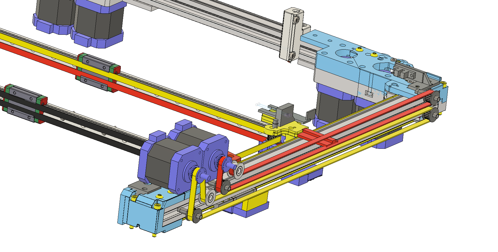
https://youtu.be/F5lyLPyndTU?si=zS3x0FlBM8Jj7b65Made a start on the IDEX belt design. My current thinking is having the two Y belts on the side of the flying gantry - with both motors at the front - to help balance the whole gantry.
The design will be mirrored on both sides of the gantry.
-
@dwuk3d said in Sovol SV08 Multiple Motion System Upgrade.:
Made a start on the IDEX belt design.
Not sure if I get it right: the two Y motors positions indicate a different kinematic model, it seems you want to use a H-bot design mixed with CoreXY? Or is it some markforge stuff?
Another problem might be the M800 macro. IDK if it's smart to use macros while printing dual stream...IMHO you should replace G10/G11 commands with the macro-content by your postprocessor
-
@o_lampe I think it is called Dual Markforge - its the same as the Ratrig Vcore4 idex - doubled up.
Attempt at demo here - although when I re look at it I think there are some errors in the animation - as it should be top belt for one X axis and bottom for the other
https://youtu.be/CjgITPc4vNg?si=SDhkxPcVuqdtXxy6Re G10/G11 - changed post processor to be aware of them and switch the Z movements to my M800's, which handle both servo and stepper based Z hopping.
Also added in G10/M800 M800/G11's around long added G0 moves due to segmenting that seems to work quite well.
Have decided to drop the servo and switch both gantries to stepper based Z hoppers - which might allow me to remove the M800's and let the G10/G11s to do the Z hopping.
Also my little Z hopping stepper isn't really up to the job I think as it is a bit slow and gets hot on idle. I'm currently turning off idle current after every move - but that makes it lose its homed status which I doubt G10/G11 would be happy with.
Tried lowering currents down to 1% instead of- but that seems to mess with parallel printing as I don't think the current changing code works well on motion system 1.
Have ordered two more motor options to try - lead screw Nema8 and lead screw Nema11 - hopefully one or both of those will be faster and have less heatup issues.
-
-
@dwuk3d said in Sovol SV08 Multiple Motion System Upgrade.:
Update - found a command by looking at the RRF code - M606 S1.
This seems to be needed to get the parallel printing to work - it is not mentioned in the Multi Motion System documentation - but is in the Gcode dictionary.
Thanks for pointing this out, this may be the reason that multiple motion systems haven't been working for people. Unfortunately, it mostly beyond my test rig (and comprehension) to test! However, from your description, I think I understand how it should be used. I've a couple of the paragraphs in the documentation to highlight M606:
https://docs.duet3d.com/en/User_manual/RepRapFirmware/Multiple_motion_systems#enabling-and-selecting-a-motion-queue
https://docs.duet3d.com/en/User_manual/RepRapFirmware/Multiple_motion_systems#command-streams-from-fileCan you check they are correct from your understanding, please?
Ian
Bed-slinger - Mini5+ WiFi/1LC | RRP Fisher v1 - D2 WiFi | Polargraph - D2 WiFi | TronXY X5S - 6HC/Roto | CNC router - 6HC | Tractus3D T1250 - D2 Eth
-
@droftarts Looks good. The only comment I have is that in my current test configuration I have the M606 near the end of the Start Gcode in Orca Slicer, not at the start of the print file - just before it starts actual printing - as I didn't need homing etc. to be parallel processed.
I wouldn't personally expect to put it in the start.g - as I wouldn't want every print to be forked, also I guess the Macro issue mentioned in this post might start occurring.
-
Managed to get Voron Tap type probing to work on the front gantry, and printing now working fairly well. Time now to return to the alignment probes.
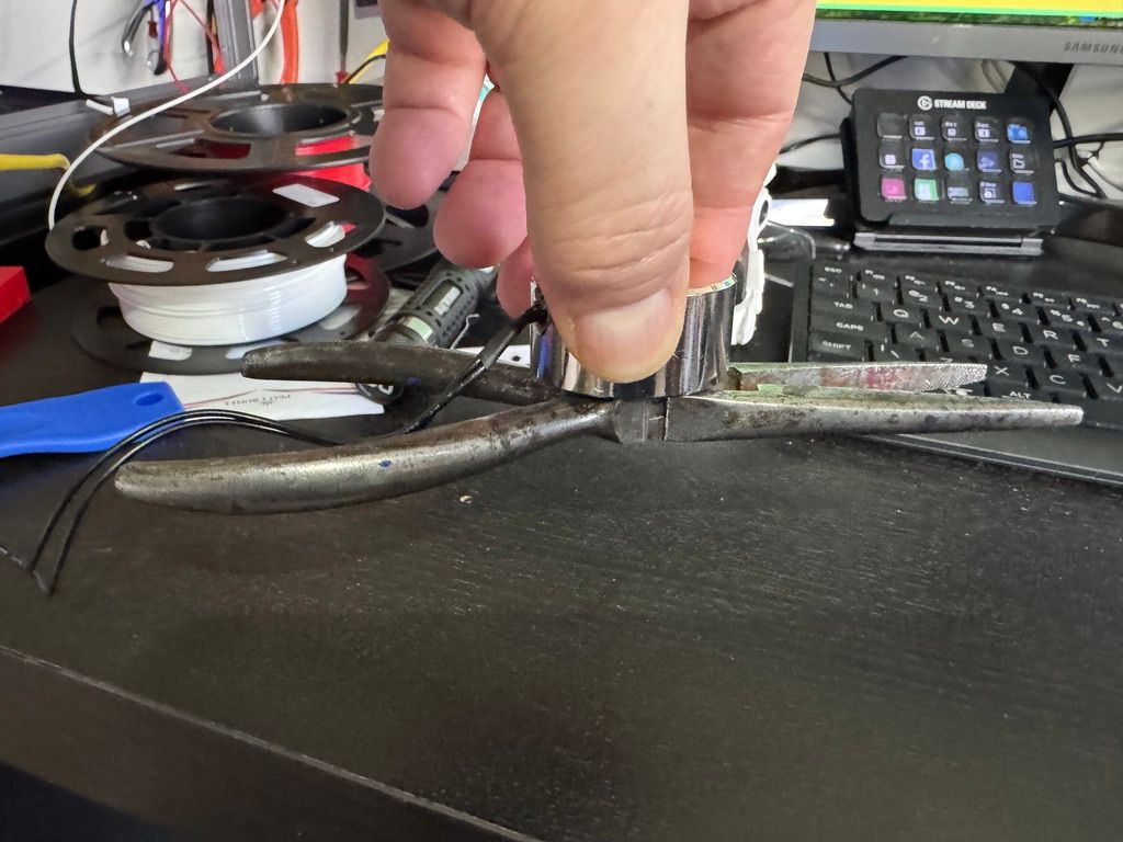
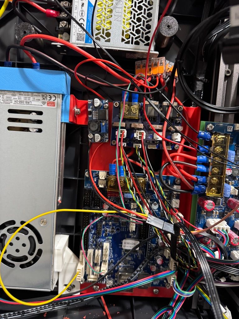
Electromagnet wired up - on Mini5+ 6A output - which has a flyback diode ok
; Electro Magnet
M950 P4 C"1.out1"
M42 P4 S0
Magnet seems to work ok - and hold pliers on anything above S30
Next on to Servo - decided to use on of these, as I have a few in stock

Powering it with 6v for now - via a LM2596 Buck Converter from the main input PSU
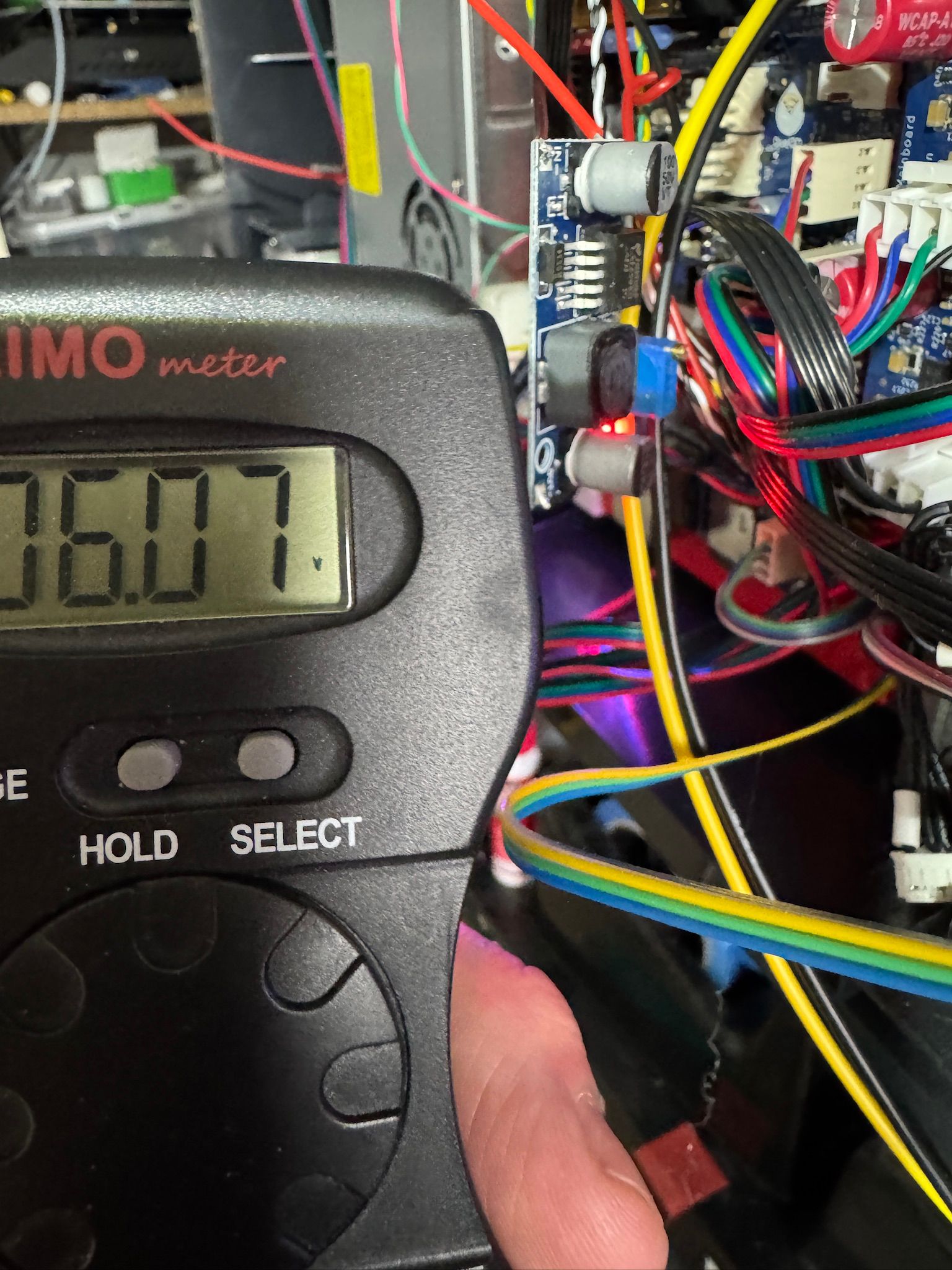
Tried it on io0 - but it didn't work as no PWM (although no error message).
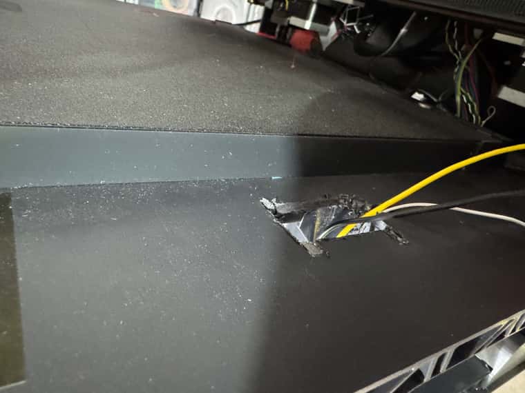
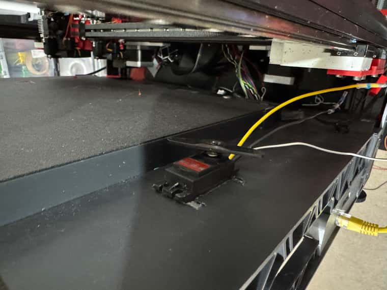
Switched to io1 and now workingM950 S0 C"1.io1.out" ; Probe Servo M280 P0 S60 ; Set ServoMade hole in case to hold servo next to bed.
3d printing of parts and macro's tomorrow.
-
@dwuk3d Those digital servos can draw a lot of current. You'd not want to block the arm or run it above the spec'd angle or the buck converter might fail.
-
@o_lampe Thanks - yes I was a little worried about that - I can't find it documented anywhere how much power the Servo uses.
It goes up to 8.4 volts - so decided to keep it down to 6v, plus also am turning off the servo as soon as I have done any moves.
Might switch to a geared stepper at some point
-
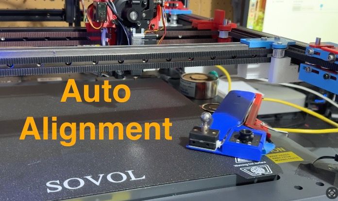
Auto alignment with ball probe complete.
Original plan was to use the electro magnet on the bed - but it is quite weak - despite specs being near to the permanent magnet that works very well.
So switched to having the magnet off the bed grabbing a big circular plate.
Not sure how much it is really needed.
Also ordered a bigger magnet - but not sure if I will need to use it.
Demo video of homing, levelling, deployment of probe and alignment attached.
-
@dwuk3d Nice video, but I watched it without sound.
The problem with any nozzle touch probes is, you have to make sure the surface is completely clean. (and conductive too?)
I hope your homing macros are ready for "murphy's law" -
@o_lampe Thanks - sorry about the music - will have to get a bit more creative with that - and maybe think about some narration.
Agreed about the nozzles needing to be clean, will have to add in some auto cleaning as part of my start up phase. I've put a cleaning pad on the swing out arm - but haven't done the automation for this yet.
The ball probe is mechanical - so no worries about conductivity.
I think my ultimate solution is likely to be a 3 stage approach - with the inductive probe or an eddy probe to find the ball probe and do some basic alignment, then using a cleaned nozzle pressing on the ball probe for a 2nd phase of alignment, with then a final check using the camera for fine adjustments,
There is some software to do the camera based adjustments automatically - but I suspect that it will be hard to get that to work reliably too - especially in different lighting conditions and with different bits of waste on the nozzle.
-
@dwuk3d Added Nozzle cleaning into alignment process, also decided to start making use of Daemon.g for timeouts of things like magnets, servo's, hot ends - which seems to be working ok.
Only issue is with the hot ends - where if the process is left on when a print is about to start then the daemon.g could drop in and switch tools - so will need to disable any tool based timers when prints are started.
Example switch on Servo and Magnet - in Probe Deploy Macro.
M42 P5 S1 ; Servo On

if exists(global.servo5Off) == false
    global servo5Off = 0

set global.servo5Off = state.upTime + 120

M42 P4 S255 ; Magnet on


if exists(global.magnetOff) == false
    global magnetOff = 0

set global.magnetOff = state.upTime + 200
Example Daemon.g
;daemon.g if exists(global.servo5Off) if global.servo5Off != 0 && global.servo5Off < state.upTime M42 P5 S0 ; Servo Off set global.servo5Off = 0 echo "daemon.g servo5 switched off" if exists(global.magnetOff) if global.magnetOff != 0 && global.magnetOff < state.upTime M42 P4 S0 ; Magnet off set global.magnetOff = 0 echo "daemon.g magnet switched off" if exists(global.T1Off) if global.T1Off != 0 && global.T1Off < state.upTime M596 P0 T1 M109 S0 set global.T1Off = 0 echo "daemon.g T1 switched off" if exists(global.T0Off) if global.T0Off != 0 && global.T0Off < state.upTime M596 P1 T0 M109 S0 set global.T0Off = 0 echo "daemon.g T0 switched off" -
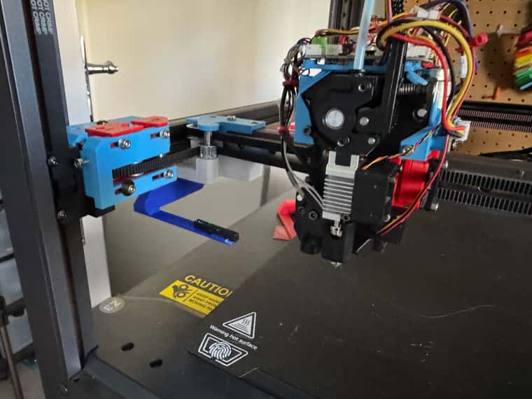
@dwuk3d Trying out various different options for head cleaner location while still waiting for Nema8 and Nema11 Z lifters to arrive.
Not sure whether to put the cleaner at the front of the gantry - so that it can be wiped in 2 dimensions,
or just on the end of the Y gantry - so can only be wiped in the X direction.I suppose I could add another servo at the end of the Y gantry, or some sort of 3d printed mechanism to make the Y wiper move backwards and forwards a little bit.
Long thin arms working quite well on low Z heights - as they bend slightly rather than fouling on the bed.
-
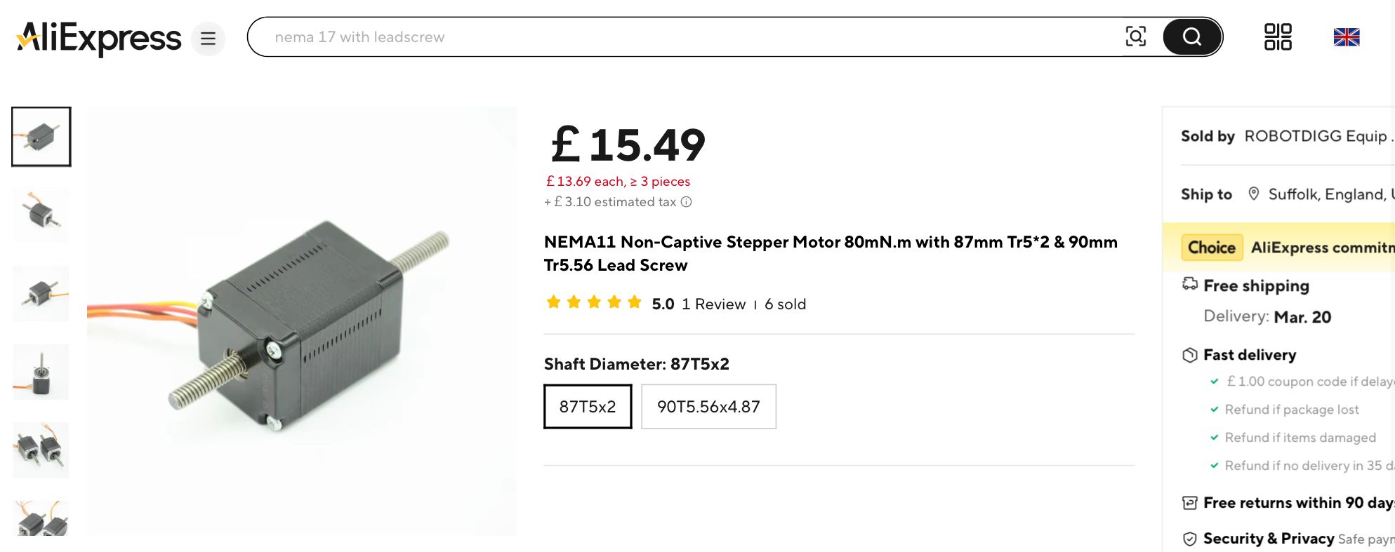
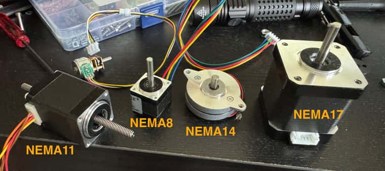
@dwuk3d NEMA11 stepper arrived.
Doesn't work quite like I expected as there is a thread inside the motor - so the lead screw has to be held for the motor to move.
Also quite heavy and bit big - so think I will hold off until the lead screw NEMA8 arrives.
Motor size comparison
-
I think Nema8 might end up working quite well for the Z hoppers.
Decided to try and create some sort of lead screw for the existing NEMA8 I got a few weeks ago.
Took quite a few iterations - but ended up doing my first ever 'captive print' - with an M4 Hex Headed Bolt captured inside a coupler print.
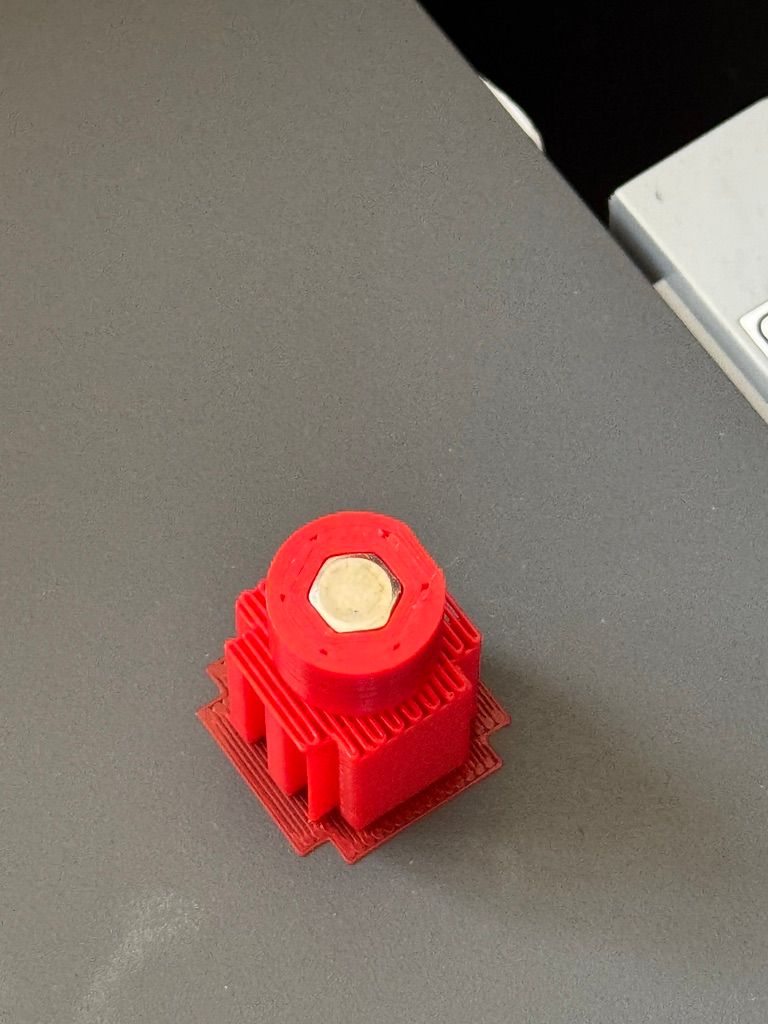
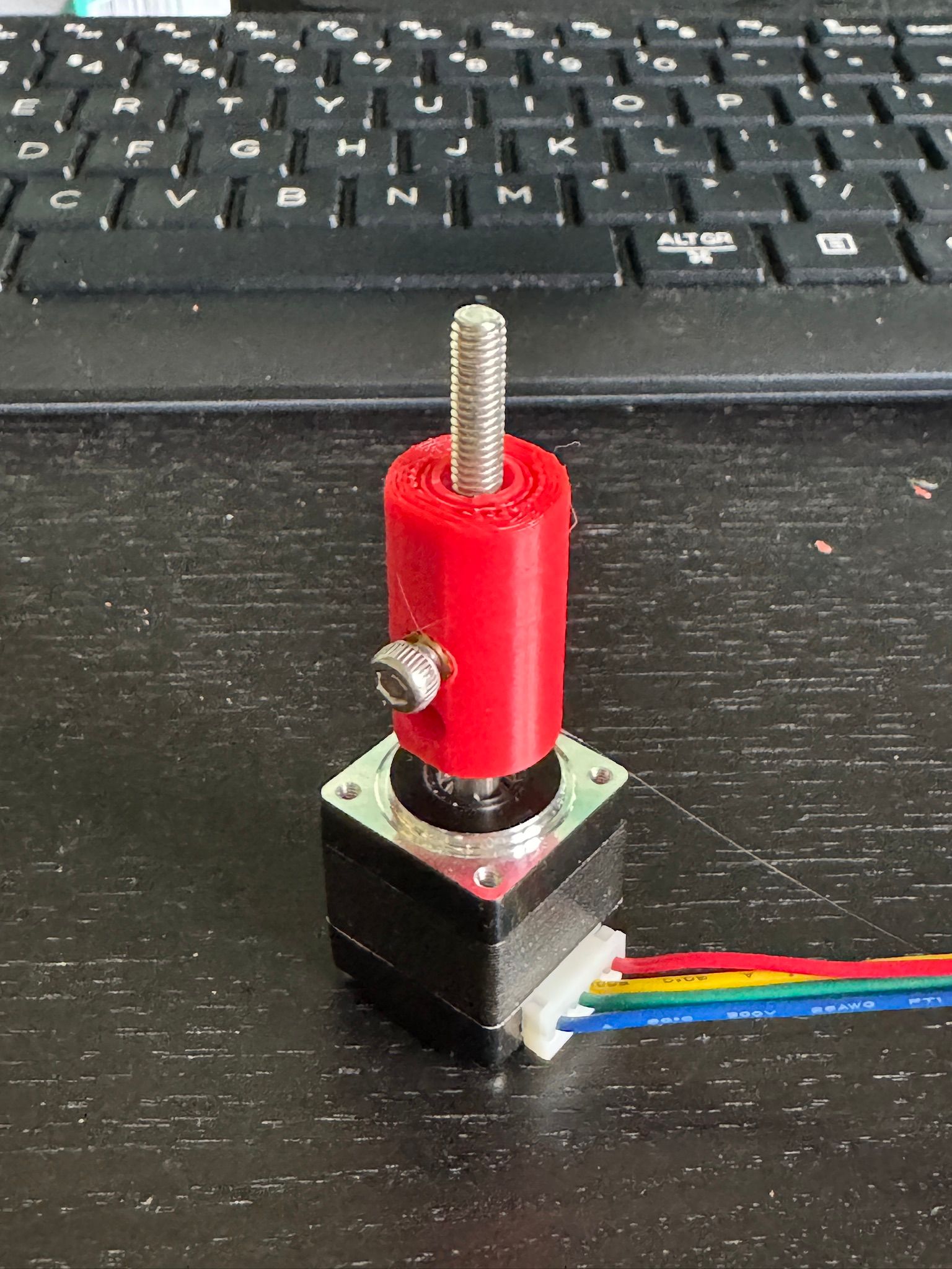
As its a bolt rather than lead screw then it is quite sloppy - but might be able to use that as a slight advantage as will hopefully be able to use a single optical end stop for both
a) The homing of the Nema8 based Z hopper
b) The X axis
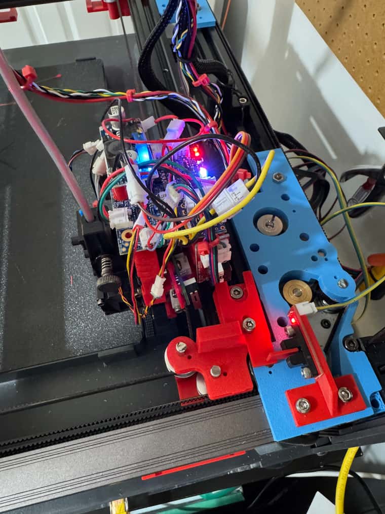
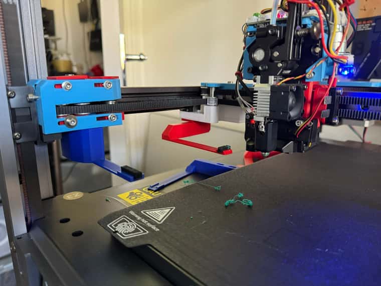
c) Z Axis tapping too.Have replaced Servo on the rear gantry with the Nema8 motor and it is looking good so far.
Comparison photo with the slow soon to be replaced front gantry stepper, rear gantry with almost completely installed NEMA8, with 3 way optical end stop below, plus the NEMA11 motor also included.
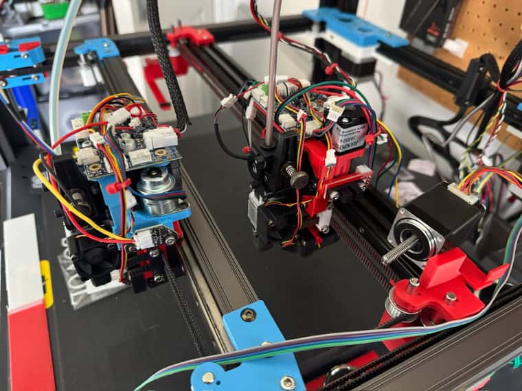
Had to move the 1LC tool board about 16mm to the left to accommodate the taller stepper/lead screw combination.
-
@dwuk3d said in Sovol SV08 Multiple Motion System Upgrade.:
As its a bolt rather than lead screw then it is quite sloppy - but might be able to use that as a slight advantage
Vertical slop is a 1st layer killer.
Although it might have advantages with other stuff, you sure don't want to risk bad adhesion to the bed.
Maybe you can add a spring to reduce backlash?