Inverting PS_ON levels
-
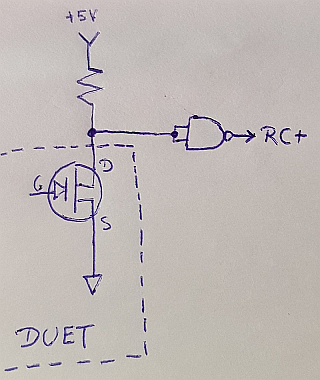
Yes, you're right. You need to use @jv43 config, using 5V from Meanwell. So this only works for this power supply. If the 5V is from another source, and this source turns off, the Meanwell remains ON

-
@insertnamehere said in Inverting PS_ON levels:
Sorry, I've not been online to answer earlier.
I leave RC- open and just connect to the RC+ input.
Are you using the 5V aux from the Meanwell or a separate 5V supply?I am using a separate 5V Meanwell supply.
@fma said in Inverting PS_ON levels:
Yes, you're right. You need to use @jv43 config, using 5V from Meanwell. So this only works for this power supply. If the 5V is from another source, and this source turns off, the Meanwell remains ON

The other 5V supply is permanently on.
-
@insertnamehere said in Inverting PS_ON levels:
@fma said in Inverting PS_ON levels:
@nxt-1 said in Inverting PS_ON levels:
While thinkering with the optocouper, I came to think if there is any good reason to not connect the transistor straight across the RC+ and RC- terminals? As I see it, this would create a short or open based on PS_ON controlling the PSU just as well as a voltage applied. If I am mistaken, please correct me
Yes, I think this is the way to go.
Hmmm.... let me check.
TO TURN ON SUPPLY.
Duet PS_ON goes to ground to turn on power. PS_ON ground will turn on the opto diode.
Opto diode on will cause the transistor to go ~ short. Short on Meanwell RC+ to RC- will turn OFF the Meanwell supply.If you connect emitter/collector of the opto across the RC+ and RC- of the supply this will not invert the PS_ON signal. That is why the emitter resistor is needed.
I tried the schematic you posted for your HFG600, that supply needs 2 ~ 5V or Open circuit to power on. In this case the ~3.3V I measured from your circuit is perfect. The HPRG I use needs 4 ~ 10V, to turn on, making the 3.3V insufficient. That is why my earlier test failed I believe.
-
Did you connect GND of both power supplies?
-
@fma said in Inverting PS_ON levels:
Did you connect GND of both power supplies?
I did not wire a connection from 5V- to 24V- terminals, however in both supplies the negative rail is connected to ground (mains ground that is) and those are of course wired up. So in a way there is a GND path between both PSU.
https://www.meanwell.com/webapp/product/search.aspx?prod=HRPG-200
https://www.meanwell.com/webapp/product/search.aspx?prod=RS-25 -
@tomasf said in Inverting PS_ON levels:
I had the same problem and solved it with a simple 7400 NAND gate chip: https://forum.duet3d.com/topic/412/inverting-ps_on
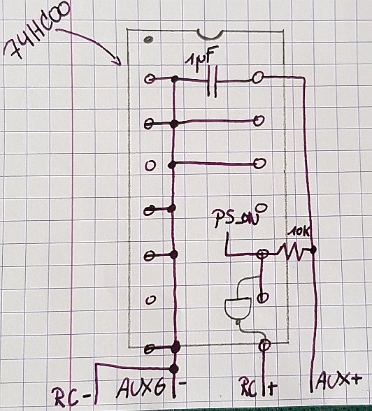
I got myself a couple of 74HC00's to plat with. I assume you you wired your system like this? What value did you use for the pull up?

-
Hy, I have an Meanwell PSPA-1000-24 and removed the bridge from the power supply. Then I connected the contacts "Ground" and "PS_on" to the power supply and connect an small 5V power supply (Jumper 5V ext!). If you switch the ATX-Power on (M80) the "PS_on" is connected to the "Ground".
It works fine!
-
@sw said in Inverting PS_ON levels:
PSPA-1000-24
A quick glance at your PSU's datasheet shows that it's RC logic is inverted compared to most Meanwell's, thus making it directly compatible with the Duet.
-
@nxt-1 said in Inverting PS_ON levels:
@tomasf said in Inverting PS_ON levels:
I had the same problem and solved it with a simple 7400 NAND gate chip: https://forum.duet3d.com/topic/412/inverting-ps_on
I got myself a couple of 74HC00's to plat with. I assume you you wired your system like this? What value did you use for the pull up?

I eventually decided to go with a 10K resistor and all seems to work as expected. I will have to get myself a small proto-board and wire things up neatly.
-
I got wired soldered up the proto-board and decided to use the auxilary 5V from the 24V PSU as I was already using the relevant connector. This results in a layout like below (unused gate input are tied to ground).
The solution is neat and compact, yet as I test it on my machine I find out that the AUXG terminal is not connected to the other grounds (not 240V L-, nor 24V V-). As a result there is to connection between the ground this circuit uses and the ground the duet used for the PS_ON pin. Back to the drawing board I go!

-
Since the AUXG and RC- terminals are already internally connected according to the datasheet, I decided to add a ring terminal to one of the ground wires I had. That connecting was then connected to V- and now all grounds are connected.
The system works fine now
-
Hey there

I have the same problem with the RSP-500 from MeanWell.
Is there no chance to change the firmware?
So M81 pulls the pin to GND and M80 opens it? -
@selecta_mota said in Inverting PS_ON levels:
Hey there

I have the same problem with the RSP-500 from MeanWell.
Is there no chance to change the firmware?
So M81 pulls the pin to GND and M80 opens it?Sadly software changes cannot compensate for things that are not there in hardware. A quick look at your PSU's datasheet shows me that its ON/OFF logic is reversed from mine's. Are you sure you cannot use it as is, maybe with a pullup in there?
-
@nxt-1 the remote is a little different on the RSP.
I need 4-10V to turn the PSU off and anything below 4V to turn it on.
When there is nothing connected to the pins on the RSP it is on, when it gets GND on pin3 and 5V (from the external 5V supply) on pin4 it turns off.
So I just need the outputs of M80 and M81 commands to be switched. -
The Meanwell logic is a non-sens: if the 5V is lost, the power supply turns on! Looks very dangerous to me...
-
@fma said in Inverting PS_ON levels:
The Meanwell logic is a non-sens: if the 5V is lost, the power supply turns on! Looks very dangerous to me...
Yeah, I know its kind of awkward but its the only PSU I could find with a bult-in remote.
It cant be that hard changing the firmware from 1 to 0 (at least thats what I hope):
 -
I have it on my RRF 3 work list to add a parameter to M80/M81 to allow the sense of PS_ON to be inverted.
-
@dc42 said in Inverting PS_ON levels:
I have it on my RRF 3 work list to add a parameter to M80/M81 to allow the sense of PS_ON to be inverted.
Hi dc42!
Is there anything new to this topic on your work list?
For me it would be extremely helpful to just reverse the pin-logic in my config file somehow -
It's on the planned 3.2 feature list.
-
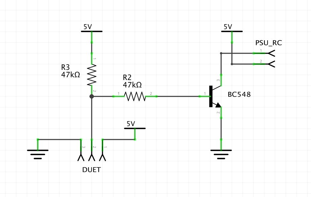
For anyone still looking for a simple solution for those Meanwell RSP Power Supplys. Here it is.

I implemented and I tested this with my Meanwell RSP-500-24 Power Supply. It works perfectly as intended.
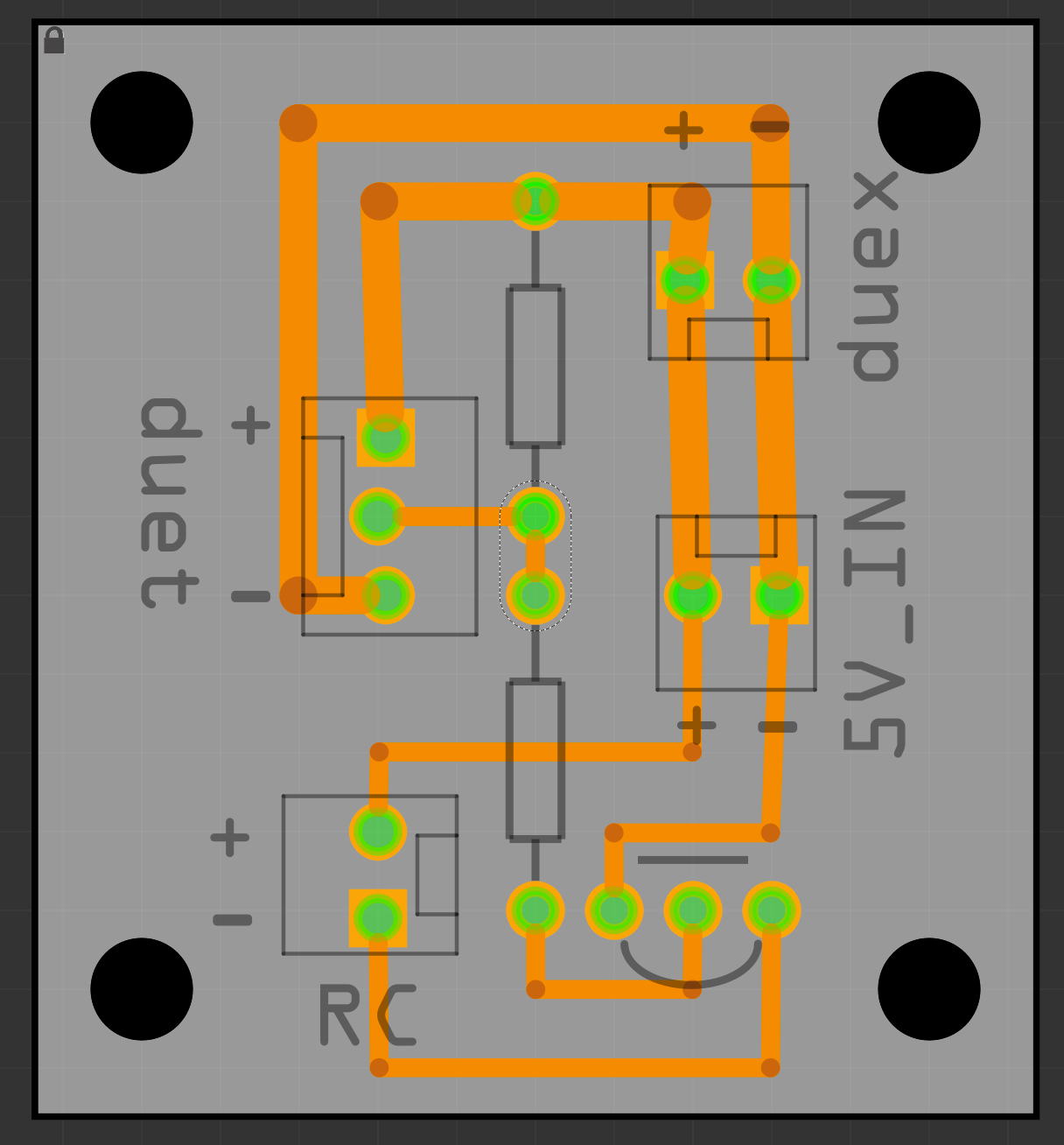
There is also a PCB-Layout, but I have not implemented it yet and hence it is untested.
