@chrishamm said in Web interface showing -273.1 in Active and Standby:
M568 P0 S0 R0
It worked thank you
@chrishamm said in Web interface showing -273.1 in Active and Standby:
M568 P0 S0 R0
It worked thank you
@adhanabal How to make it show as Zero?
; Sensors
M308 S0 P"temp0" Y"thermistor" A"Cooling Head" T100000 B4725 C7.06e-8 ; configure sensor #1
M308 S1 P"temp1" Y"thermistor" A"Heating Head" T100000 B4725 C7.06e-8 ; configure sensor #0
M308 S2 P"temp2" Y"thermistor" A"Heating Bed" T100000 B4725 C7.06e-8 ; configure sensor #1
; Heaters
M950 H0 C"out0" T0 ; create heater #1
M143 S38 ; configure heater monitor #0 for heater #1
M307 H0 R2.43 D5.5 E1.35 K0.56 B0 I1 ; configure model of heater #1
M950 H1 C"out1" T1 ; create heater #0
M143 S250 ; configure heater monitor #0 for heater #0
M307 H1 R2.43 D5.5 E1.35 K0.56 B1 ; configure model of heater #0
M950 H2 C"out2" T2 ; create heater #1
M143 S85 ; configure heater monitor #0 for heater #1
M307 H2 R2.43 D5.5 E1.35 K0.56 B0 ; configure model of heater #1
; Heated beds
M140 P0 H2 ; configure heated bed #0
; Tools
M563 P0 S"Head 1" D0 H0 ; create tool #0
G10 P0 X0 Y0 Z0 ; set tool 0 axis offsets
M563 P1 S"Head 2" D0 H1 ; create tool #1
G10 P1 X45 Y0 Z0 ; set tool 0 axis offsets
M563 P2 S"Head 3" D0 ; create tool #2
G10 P2 X90 Y0 Z0 ; set tool 0 axis offsets
M563 P3 S"Head 4" D0 F3 ; create tool #3
G10 P3 X135 Y0 Z0 ; set tool 0 axis offsets
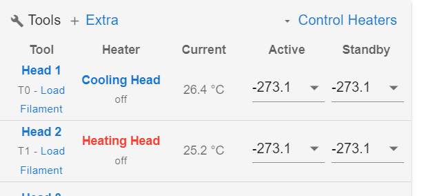
Hi
Why it is showing like this instead of 0? RRF version 3.5.4

Hi all
I'm using IR heaters to heat my chamber,
I placed my temperature sensor far from heater to get perfect chamber temperature readings,
Problem is heater going to fault, stating temperature raise is too low, 0.1deg/sec
How can I overcome this issue,
I tried PID tuning but it was taking 2 hours to reach phase 3 (measuring) , and didn't complete the tuning.
Any guidance please
@Phaedrux https://robu.in/product/xd-1037-dc12v-60w-semiconductor-refrigeration-sheet-refrigerator-diy-refrigeration-plate-low-power-radiator-system/?gad_source=1&gclid=CjwKCAjwy8i0BhAkEiwAdFaeGPngI6QUG2MbtXkZJg9Zr10fg__W5pp7QXcpx8d4QRaPuV4eEgxCmhoCZ1MQAvD_BwE
Product Name
Semiconductor Refrigeration Plate
Model
XD-1037
Power Supply Voltage
DC12V
Energy consumption
60W
Shipping Weight 0.4 kg
Shipping Dimensions 12 × 8 × 6 cm
I want to have a cooling head for a paste extrusion,
Which need 4 -10 deg c, I want to use Thermo electric cooler, how to integrate?
Do duet3d boards support this?
@dc42 Hi i checked the page , it suggested me to use the following board instead of the one im using

@o_lampe hi no it dint blowup anything
Description:
Features:
1>. MCU embedded technology
2>. Easy to operate, fine tuned by potentiometer
3>. Select the PWM signal input level range through short-circuit
4>. The module is smaller, easy to carry and use
Parameter:
1>. Work Voltage:DC 12V-30V; (> 100MA)
2>. PWM Receiver Frequency:1KHZ-3KHZ
3>. PWM signal input level range:
The peak of 4.5V to 10V level. The short cap install in ‘5V’. This level is used for normal controller or 5V MCU
The peak of 12V to 24V level, so inserted in 24V. The short cap install in ‘24V’. This level is used for normal PLC controller
4>. Conversion range:0%-100% PWM to 0-10V
5>. Allowable error:5%
Hardware Interface:
VCC DC 12V-30V
GND Ground
PWM Positive of PWM input signal
GND Negative of input signal
VOUT Output Voltage 0-10V
GND Output Voltage Ground
Hi all
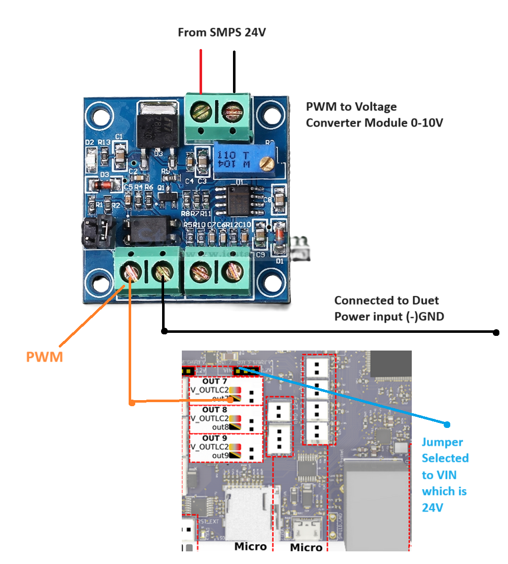
I want to use duet fan ports for pwm control, so that i can take Output voltage from converter module to control a Proportional Regulator which regulates pressure using 0-5V where 0 means 0 bar, 5 means 5 bar pressure.
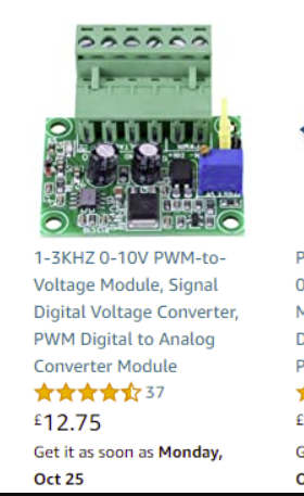
Link of the Converter im using,
https://www.icstation.com/voltage-converter-module-adjustable-converter-power-module-digital-analog-signal-p-12498.html
And my wiring, im not sure it is correct or not!

In config.g i have tried the following options individually, but nothing worked. can you please help .
M950 P0 C"out7" Q1000 ; create fan 0 on pin out7 and set its frequency
M42 P0 S0
(Individually tried)
M950 F0 C"out7" Q1000 ; create fan 0 on pin out7 and set its frequency
M106 P0 S1 H-1 ; set fan 0 value. Thermostatic control is turned off
Is there any way I can make interactive images in panel due or DWC?
Similar to M291 command which displays text.
Instead of text is it possible to have images?
@MJLew In tpre0 i had put a wrong code.
@droftarts Hi thank you i have resolved the issue succesfully
Im getting this error while tool change happening

@dc42 if I connect with 12v and ground I'm getting under voltage  warning. Should I use separate 12v power supply?
@dc42 can you please answer thisa
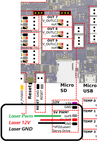
I have 5W diode laser which has 3 pins , 12v Power, Pwm pin and GND pin, how to connect to duet 3 6hc board?
Is it correct?,
