@droftarts thank you
Posts made by aldiallo
-
RE: Questions regarding CAN setup with Duet 3 6hc and Duet 3 mini 5+posted in General Discussion
@droftarts Hi, thanks for the detailed responses.
Concerning the boards, I'm currently running 2 mini 5+, one on my Ender 5+ and 1 on my Sidewinder; (I do have the 6hc in her box waiting for a future project ( Voron or RatRig, haven't made a choice yet and currently need to figure out space in the garage as no more available space in the house) so will be 2-pin KK connector.
I've received the Roto tool head and I see the cable your talking about, I was asking about the cable as a just in case I might be short on the the cable length; I also ordered the Duet 3 Scanning Probe Z probe, am I right to think that I can plug it directly to the Roto tool head and not used the board that comes with it?
If all goes well with the Artillery, the Ender will follow suit; I'm maybe bitting more than I can chew but for me it's an exciting project!!

-
RE: Questions regarding CAN setup with Duet 3 6hc and Duet 3 mini 5+posted in General Discussion
@jay_s_uk Hi,
Thanks for the confirmation on the roto toolboard, concerning the Fly-SHT36 Max V3, I never heard of it before will also have a look.
-
RE: Questions regarding CAN setup with Duet 3 6hc and Duet 3 mini 5+posted in General Discussion
@Phaedrux Hi,
Thanks for the links, I did came accros the can connection page but did not do a deep dive on in.
So there's no "incompatibility issues" by using the roto toolboard instead of the 1LC, that's good to know; my aim is to have only one cable going back to the board and thought that the roto would be more "future proof" than the 1LC. I'll be using the Mini 5+ to start on my sidewinder X1 to begin with and if all good with do the same with the Mini 5+ on my Ender 5+.
-
Questions regarding CAN setup with Duet 3 6hc and Duet 3 mini 5+posted in General Discussion
Hi all,
I have a couple of questions as I've been using duet boards for some time now but mainly with Klipper and I'm thinking to go back to the original RRF as I would like to use CAN and it seems to be simpler to implement if using RRF.
1st of all is that "simpler" statement true ?
2- In the idea of getting this implemented, what toolhead would you recommend using with a Hemera hotend, the standard one not the xs; the 1LC v1.2? or is the latest Roto toolhead an option ?
3- I wasn't able to find the CAN bus cable in the website, is the cable available for purchase or I need to build it myself (I know the cables are different between the 6hc and the mini 5+) ?
4- In Klipper for can you need to flash both board, is that also the case in RRF or this is automatically done when you setup your firmware with the configurator tool?
5- When replacing Klipper with RRF, how should I go about that process, meaning can I just use the configurator tool with the latest firmware or do I need to do start with an older version of the RRF and do incremental upgrades till I get to the latest version, this might be a silly question but I prefer to look silly and not brick my boards than look stupid after bricking them!This are the questions I currently have, some may come later following the answers I get, in any case many thanks for your answers and help.
-
RE: [Solved] Sidewinder X1 SKR replacement with Duet 3 mini 5+posted in Duet Hardware and wiring
@Falcounet @Herve_Smith
Hi, Thanks for taking the time to reply, actually I ended up answering my question earlier a couple of hours ago and have been finishing the printer configuration. the cable in question if anyone else looks fo the info in the future is the filament sensor.
Concerning the RPI, I'll be running the printer with Klipper not with original firmware hence why the RPI is requiered in my case.
I now got everything working as expected including the filament sensor so all well and good; again appreciate your time replying, especially that it was a dumb prep error on my side when I starting labelling and unpluging the cables from the SKR.
-
RE: [Solved] Sidewinder X1 SKR replacement with Duet 3 mini 5+posted in Duet Hardware and wiring
Anyone using a Duet 3 mini with an Artillery Sidewinder that could point in me in the right direction please?
Thanks
-
[Solved] Sidewinder X1 SKR replacement with Duet 3 mini 5+posted in Duet Hardware and wiring
Hi all,
After several years using a Duet 3 6HC in my ender 5 Plus, I've replaced the Duet 3 6HC with a duet 3 mini 5+ and I'm saving the Duet 3 6HC for a future project. In the past I posted here my project of replacing an SKR 1.4 turbo with the Duet3 6HC, after long time hesitating and with the duet 3 mini giving great results on the Ender 5+, I decided to pull the gun en replace the SKR with the mini.
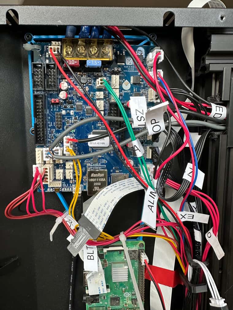
That being said, I've starting cabling the new board to the artillery, I believe that I'm mostly done but I'm having some issues identifying some of the cables; I have an adapter on a white cable that you can see at the bottom right of the image.
Can someone please confirm what the white cable is and where should it be plugged in also(I completely forgot to label it
 ), is any one also using a BL touch or a super pinda with the sidewinder x1 ?
Also I believe I can power up a raspberry pi from one of the 5V connectors if so what would be the best pins to use in this case??
FYI, I have no screen connected.
Thanks in advance for your help.
-
RE: Extruding issue after installing an E3D Hemeraposted in Tuning and tweaking
Thanks for the feedback guys, I'll retune my slicer settings and see what comes out and use a temp tower to nail the ebst printing temps for the filament being used. I'm also considering moving from Simplify3D to either PrusaSlicer or SuperSlicer once I get the new settings nailed in.
-
RE: Extruding issue after installing an E3D Hemeraposted in Tuning and tweaking
May I ask you what your slicer settings are for the Hemera please? I've done 3 prints trying to nailed settings down but I still have some issues as you can see in the images below:


The first print was the calibration cube on the right then the one on the left and finally the benchy. I'm using Simplify3d and between the first and second cube I raised the temperature from 210 to 235 and disabled retraction so layer adhesion was better but needs to be improved.
If I compare the benchy to one of the one printed with the previous setup using the Microswiss Direct drive setup, I wasn't expecting the difference to be so huge, not sure why but I hoping that the changes required on the slicer would be minimal but I was complety wrong


Current setting after disabling retraction, the extrusion multiplier was raised from 0.90 to 0.95 and the extrusion witdth was changed form manual .0.40 to Auto, Coasting and Nozzle wipe are enable .
Layer height is set to 0.32
Any suggestions?
Thanks
-
RE: Extruding issue after installing an E3D Hemeraposted in Tuning and tweaking
@rjenkinsgb spot on!
Thanks, that was it, extrusion working fine, really appreciate your help on this.
-
RE: Extruding issue after installing an E3D Hemeraposted in Tuning and tweaking
Hi @rjenkinsgb,
Thanks for taking the time to reply, I have M83 setup in my general preferences in my config.g as per below, so not sure if that changes anything or if maybe I need to replace it with M82 instead,:
General preferences
G90 ; send absolute coordinates...
M83 ; ...but relative extruder moves
M550 P"Ender 5 Plus" ; set printer nameAlso, it seems that I'm using the same E409 steps/mm, E16 and I1 values as you are so I'm a bit confused to be honest.
Concerning directions I'll keep it as S1which is extruding.
-
Extruding issue after installing an E3D Hemeraposted in Tuning and tweaking
Hi all,
I'm having an issue on my Ender 5 Plus when trying to calibrate the extrusion following the replacement of a Microswiss hotend with a Hemera, I'm using a Duet 3 board the normal one not the mini.
When sending a G1 E100 F3000 command in the console I just get about 4,5mm extruded.
I believe the changes on config.g to be correct but I'm clearly missing something or my Hemera is faulty:
; Drives
M569 P0.0 S0 ; physical drive 0.0 goes backwards
M569 P0.1 S0 ; physical drive 0.1 goes backwards
M569 P0.2 S0 ; physical drive 0.2 goes backwards
M569 P0.4 S1 ; physical drive 0.4 goes backwards
M584 X0.0 Y0.1 Z0.2:0.3 E0.4 ; set drive mapping
M350 X16 Y16 Z16 E16 I1 ; configure microstepping with interpolation
M92 X80.00 Y80.00 Z800.00 E409 ; set steps per mm
M566 X900.00 Y900.00 Z12.00 E300.00 ; set maximum instantaneous speed changes (mm/min)
M203 X6000.00 Y6000.00 Z1200.00 E3600.00 ; set maximum speeds (mm/min)
M201 X500.00 Y500.00 Z20.00 E5000.00 ; set accelerations (mm/s^2)
M906 X800 Y800 Z800 E800 I30 ; set motor currents (mA) and motor idle factor in per cent
M84 S30 ; Set idle timeoutI changed the S value to 1 on the M569 P0.4 line in order to get the filament extruded but I must admit that I was surprised I had to do this, as it was working fine with the previous motor, so maybe that the hemera motor is setup to turn in the other direction, this is the only thing I can think of right now.
Anyone one has an idea of what I'm missing here, I'll appreciate any insight !
Thanks
-
RE: G29 command skipping grid pointsposted in Tuning and tweaking
Hello,
Nothing at first sight, bed look flat to me but what I can say is that the first layer sticks better in the middle and back and also on the front right side, I'm a bit far on the left corner, so need to redo my manual bed level again. This is using the stock bltouch with the stock mount but not the stock glass bed as I replaced it with TH3D EzFlex smooth PEI and a magnetic base
-
RE: G29 command skipping grid pointsposted in Tuning and tweaking
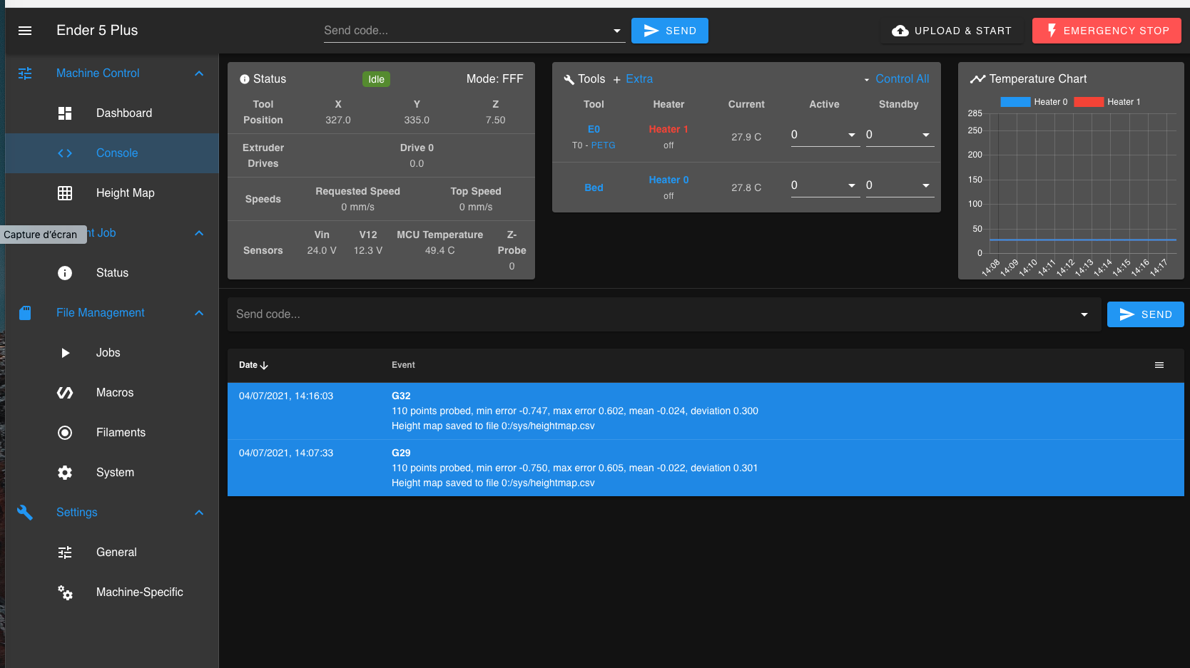
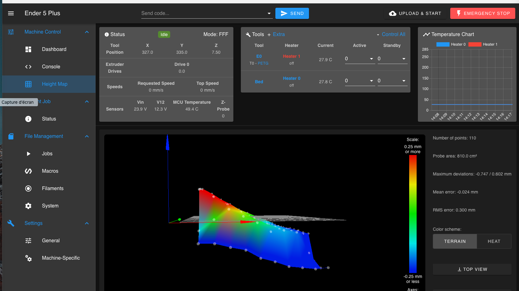
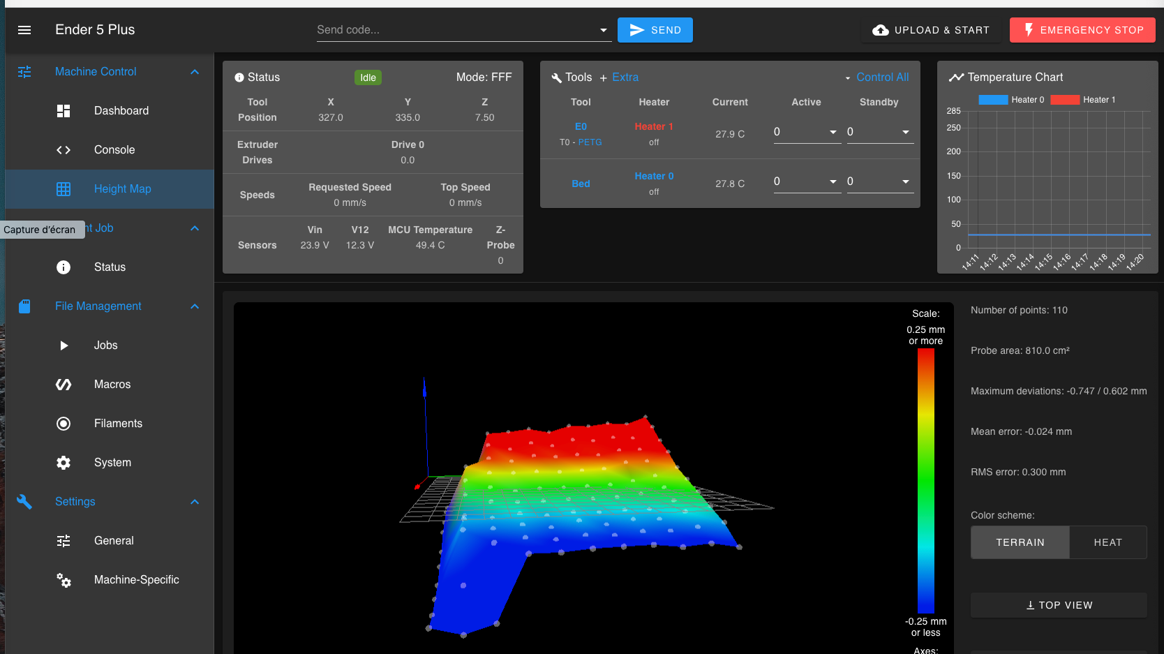
just tried it and I'm no longer getting the error but now I'm a bit concerned about the results, not sure if this is good or not:
-
G29 command skipping grid pointsposted in Tuning and tweaking
Hi all,
I have an issue when running G29 command on my Ender 5 where I'm getting the error message: Warning : Skipping grid point ( X,Y) because Z probe cannot reach it as you can see below:
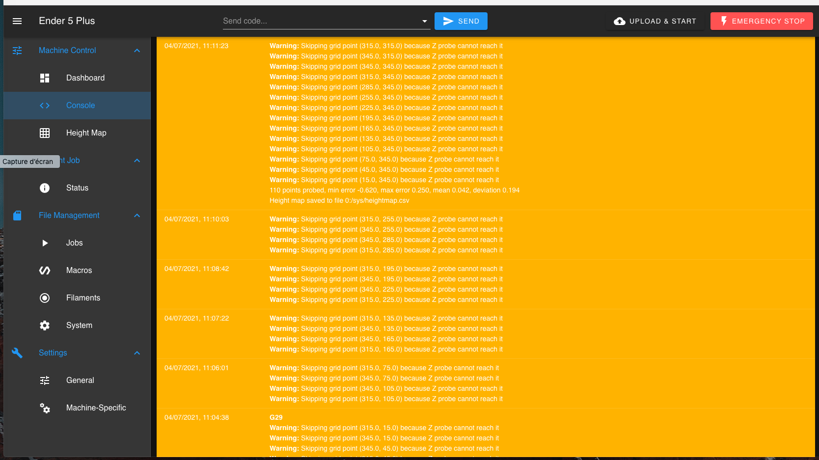
This must be an issue with my config.g and how i defined my grid and number of points to test but I cannot figure out exactly what parameter I got wrong, here's my config.g if someone can help point me to pin point the issue.
; Configuration file for Duet 3 (firmware version 3)
; executed by the firmware on start-up
;
; generated by RepRapFirmware Configuration Tool v3.1.4 on Sun Oct 04 2020 22:37:40 GMT+0200 (heure d’été d’Europe centrale); General preferences
G90 ; send absolute coordinates...
M83 ; ...but relative extruder moves
M550 P"Ender 5 Plus" ; set printer name; Network
M552 P0.0.0.0 S1 ; enable network and acquire dynamic address via DHCP
M586 P0 S1 ; enable HTTP
M586 P1 S0 ; disable FTP
M586 P2 S0 ; disable Telnet; Drives
M569 P0.0 S0 ; physical drive 0.0 goes backwards
M569 P0.1 S0 ; physical drive 0.1 goes backwards
M569 P0.2 S0 ; physical drive 0.2 goes backwards
M569 P0.4 S0 ; physical drive 0.4 goes backwards
M584 X0.0 Y0.1 Z0.2:0.3 E0.4 ; set drive mapping
M350 X16 Y16 Z16 E16 I1 ; configure microstepping with interpolation
M92 X80.00 Y80.00 Z800.00 E130.00 ; set steps per mm
M566 X900.00 Y900.00 Z12.00 E120.00 ; set maximum instantaneous speed changes (mm/min)
M203 X6000.00 Y6000.00 Z1200.00 E1200.00 ; set maximum speeds (mm/min)
M201 X500.00 Y500.00 Z20.00 E250.00 ; set accelerations (mm/s^2)
M906 X800 Y800 Z800 E800 I30 ; set motor currents (mA) and motor idle factor in per cent
M84 S30 ; Set idle timeout; Axis Limits
M208 X0 Y0 Z0 S1 ; set axis minima
M208 X350 Y350 Z400 S0 ; set axis maxima; Endstops
M574 X2 S1 P"io1.in" ; configure active-high endstop for high end on X via pin io1.in
M574 Y2 S1 P"io2.in" ; configure active-high endstop for high end on Y via pin io2.in
M574 Z2 S2 ; configure Z-probe endstop for high end on Z; Z-Probe
M950 S0 C"io4.out" ; create servo pin 0 for BLTouch
M558 P9 C"^io4.in" H5 F120 T6000 ; set Z probe type to bltouch and the dive height + speeds
G31 P500 X-42 Y-20 Z2.503 ; set Z probe trigger value, offset and trigger height
M557 X15:350 Y15:350 S30 ; define mesh grid; Heaters
M308 S0 P"temp1" Y"thermistor" T100000 B4092 ; configure sensor 0 as thermistor on pin temp1
M950 H0 C"out0" T0 ; create bed heater output on out0 and map it to sensor 0
M307 H0 B0 S1.00 ; disable bang-bang mode for the bed heater and set PWM limit
M140 H0 ; map heated bed to heater 0
M143 H0 S120 ; set temperature limit for heater 0 to 120C
M308 S1 P"temp0" Y"thermistor" T100000 B4092 ; configure sensor 1 as thermistor on pin temp0
M950 H1 C"out1" T1 ; create nozzle heater output on out1 and map it to sensor 1
M307 H1 B0 S1.00 ; disable bang-bang mode for heater and set PWM limit; Fans
M950 F0 C"out7" Q500 ; create fan 0 on pin out7 and set its frequency
M106 P0 C"Part cooling fan" S0 H1 T45 ; set fan 0 name and value. Thermostatic control is turned on
M950 F1 C"out8" Q500 ; create fan 1 on pin out8 and set its frequency
M106 P1 C"Hot-end fan" S1 H1 T45 ; set fan 1 name and value. Thermostatic control is turned on
M950 F2 C"out4" Q500 ; create fan 2 on pin out4 and set its frequency
M106 P2 C"Motherboard fan" S1 H-1 ; set fan 2 name and value. Thermostatic control is turned off
M950 F3 C"out9" Q500 ; create fan 2 on pin out4 and set its frequency
M106 P3 C"Case fan" S1 H-1 ; set fan 2 name and value. Thermostatic control is turned off; Tools
M563 P0 S"E0" D0 H1 F0 ; define tool 0
G10 P0 X0 Y0 Z0 ; set tool 0 axis offsets
G10 P0 R0 S0 ; set initial tool 0 active and standby temperatures to 0C
M563 P1 S"E1" D1 H2 F0 ; define tool 1
G10 P1 X0 Y0 Z0 ; set tool 1 axis offsets
G10 P1 R0 S0 ; set initial tool 1 active and standby temperatures to 0C; Filament runout sensor
;M581 E2 T1 S0 C1 ; Filament run-out sensor triggers a pause; Custom settings are not defined
; Miscellaneous
M575 P1 S1 B57600 ; enable support for PanelDueM501
Thanks in advance for you help
-
RE: Artillery X1 Duet3 6HCposted in Duet Hardware and wiring
Hello,
The SKR1.4 and yeah I read about the possibility of running RRF on it but as I'm already running the 6HC on my Ender 5 Plus and that I'm quite happy with it, I said to myself, go for it
")
-
Artillery X1 Duet3 6HCposted in Duet Hardware and wiring
Hi all,
After installing my first duet board on my Ender 5 plus a few months back, I'm itching to do the same on my Artillery Sidewinder X1 printer to be using à single printing platform, so I'm wondering if anyone has installed a Duet3 6HC in an Artillery X1 printer??
I'll be replacing a Bigtreetech motherboard with 5160 drivers. I've also read that the they're some slight differences like endstops @ 5V in X1 vs 3.3V on the Duet side, any other things I should be paying attention to?
Thanks