Is there a way to monitor the filament sensors movement/status, similar to how the z probe sensor is monitored and displayed in the status window. Id like to be able to glance at the monitor instead of always having to look at the printer/filament sensor. If its not available I think it would be a nice addition.
Posts made by aprz
-
monitor the filament sensor through the status windowposted in Duet Web Control
-
RE: Heater fault issue while tool 0 fan is onposted in Tuning and tweaking
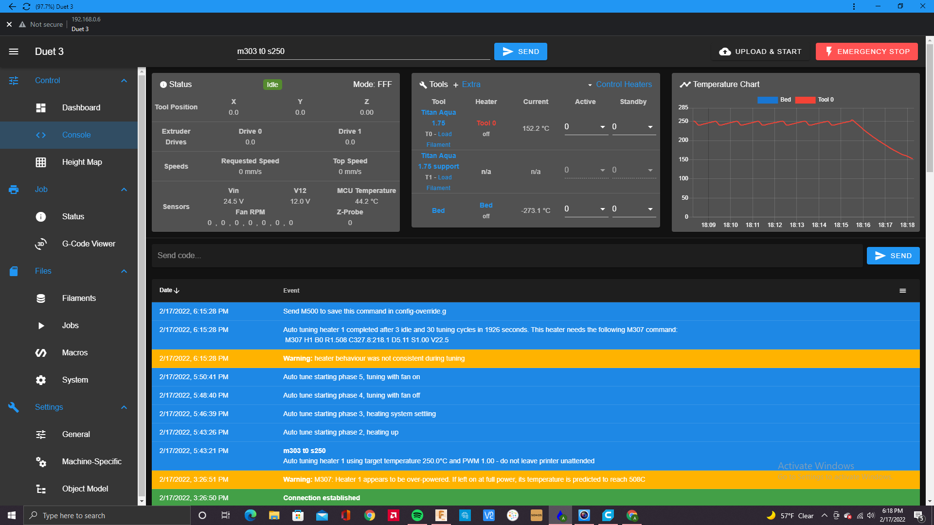
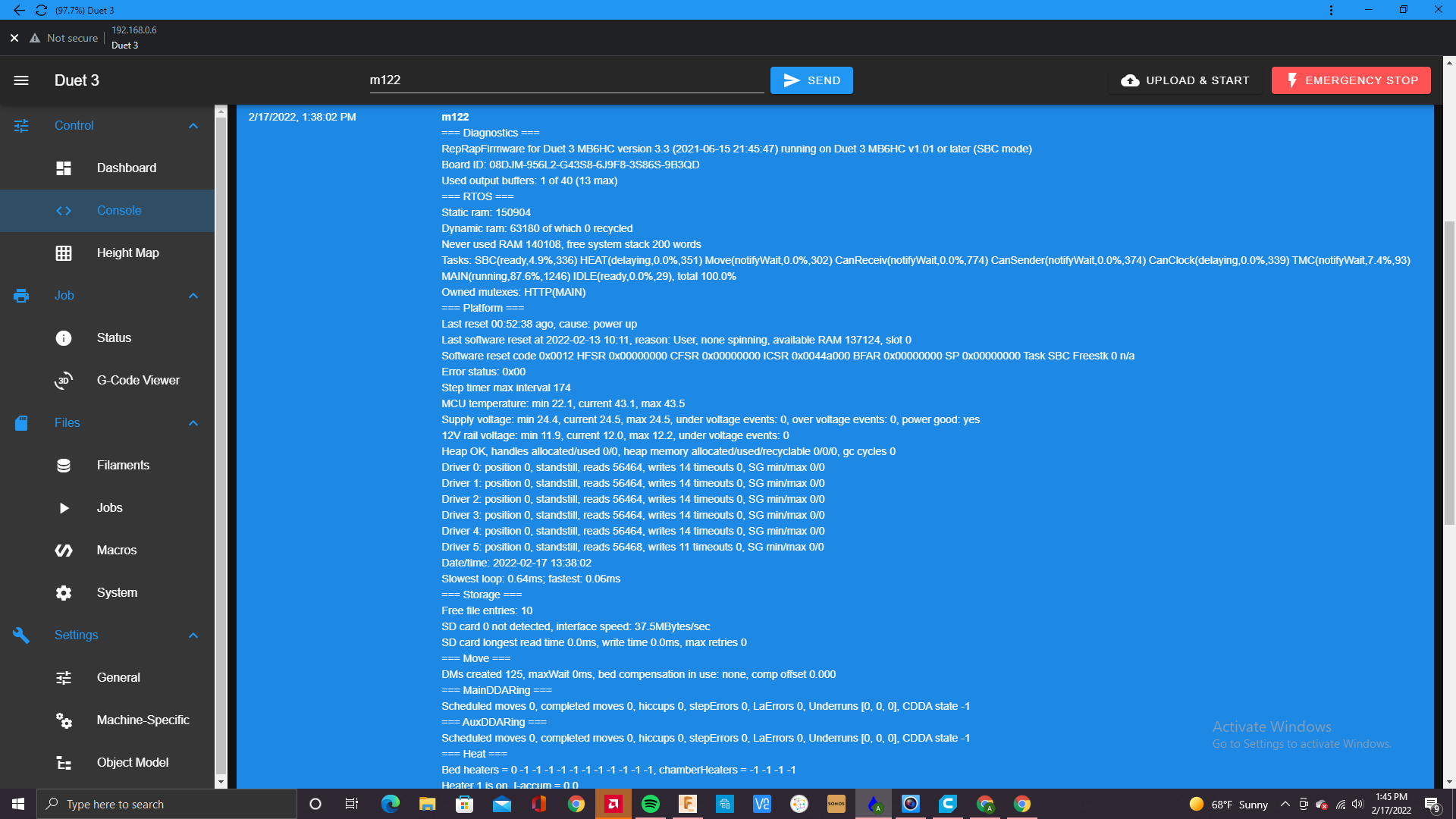
@phaedrux I ran the M303 H0 S250 twice and the message I got in the event log, below is a screen shot. I'm not sure what is causing that warning. I've changed the heater as well but didn't seem to fix the issue, what else could it be? Again thanks for the help.
-
RE: Heater fault issue while tool 0 fan is onposted in Tuning and tweaking
@phaedrux Thanks. I'll recalibrate with the M303 T0 S250 instead of the other, that may be why the fault keeps occurring.
-
Heater fault issue while tool 0 fan is onposted in Tuning and tweaking
I've been having an issue recently with the heater faulting while the part cooling fan is on during a print. I'm assuming its a gcode error but would appreciate any help and suggestions. Also, after doing a heater calibration I noticed the voltage for the heater is 22.2, (M307 H1 R1.683 C322.300:307.700 D4.10 S1.00 V22.2 B0) is that normal.
Thanks.Here's my config file:
; General preferences
G90                                                     ; send absolute coordinates...
M83                                                     ; ...but relative extruder moves
M550 P"Duet 3"                                          ; set printer name

; Wait a moment for the CAN expansion boards to start
G4 S2

; Network
;M552 P0.0.0.0 S1                                                                                        ; enable network and acquire dynamic address via DHCP
;M586 P0 S1                                                                                              ; enable HTTP
;M586 P1 S0                                                                                              ; disable FTP
;M586 P2 S0                                                                                              ; disable Telnet


; Drives
M569 P0.4   S1                                                                ; X axis right motor physical drive 0.4 goes forwards
M569 P2.2   S1                                                                ; X axis left motor physical drive 2.2 goes forwards
M569 P2.0   S1                                                                ; Y axis physical drive 2.0 goes forwards
M569 P2.1   S1                                                                ; Y axis physical drive 2.1 goes forwards
M569 P1.1   S0                                                                ; Y axis physical drive 1.1 goes forwards
M569 P1.0   S0                                                                ; Y axis physical drive 1.3 goes backwards
M569 P0.0   S1                                                                ; Z axis physical drive 0.0 goes forwards
M569 P0.1   S1                                                                ; Z axis physical drive 0.1 goes forwards
M569 P0.2   S1                                                                ; Z axis physical drive 0.2 goes forwards
M569 P0.3   S1                                                                ; Z axis physical drive 0.3 goes forwards
M569 P20.0  S0                                                                ; Tool 1 physical drive 20.0 goes forwards
M569 P21.0  S1                                                                ; Tool 2 physical drive 21.0 goes forwards
M584 X0.4:2.2 Y2.0:2.1:1.1:1.0 Z0.0:0.1:0.2:0.3 E20.0:21.0                ; Four Z motors connected to driver outputs Z axis
M671 X-30:-30:890:890    Y-30:890:890:-30  S2                             ; leadscrews at rear left, front left, front right, rear right (connected to Z)
M208 X0:820 Y0:820 Z0:800                                                 ; X axis moves from 0 to 845, Y axis goes from 0 to 840, Z Moves from 0 to 800, C moves from -45 to 360
M350 X16       Y16       Z16              E16:16            I1            ; configure microstepping with interpolation
M92  X52.49    Y104.99   Z3200.00         E837.00:837.00                  ; set steps per mm
M566 X420.00   Y420.00   Z270.00          E7000.00:7000.00                ; set maximum instantaneous speed changes (mm/min)
M203 X7250.00  Y7250.00  Z350.00          E10000.00:10000.00              ; set maximum speeds (mm/min)
M201 X300.00   Y300.00   Z270.00          E8000.00:8000.00                ; set accelerations (mm/s^2)
M906 X3600     Y2900     Z2500            E1100:1100          I30         ; set motor currents (mA) and motor idle factor in per cent
M84  S30                                                                  ; Set idle timeout

; Axis Limits
;M208 X0:845 Y0:890 Z0:800                                               ; X axis moves from 0 to 845, Y axis goes from 0 to 840, Z Moves from 0 to 800, C moves from -45 to 360


; Filament sensors
M591 D0 P3 C"20.io1.in" S1 R82:131 L27.47 E90.0                                ; Duet3D rotating magnet sensor for extruder drive 0 is connected to E0 endstop input, enabled, sensitivity 24.8mm.rev, 80% to 135% tolerance, 5mm detection length
;M591 D1 P1 C"21.io1.in" S1                                                   ; filament monitor connected to pin 21.io1.in
;M591 D0 P1 C"0.io0.in"  S1                                                   ; filament monitor connected to pin 3.io3.in


;Extra sensor
M308 S10 Y"mcu-temp" A"MCU"

; Endstops
M574 X1 S1 P"2.io2.in"                                       ; configure active-low endstop for low end on X via pin 2.io2.in
M574 Y1 S1 P"1.io2.in"                                       ; configure active-low endstop for low end on Y via pin 1,io2.in
M574 C0 Z0  		                           				 ; No C Z endstop


; Z-Probe
M558 P8 C"!21.io0.in" H3 F150                                ; set Z probe type to unmodulated and the dive height + speeds
G31  P500 X0 Y0 Z1.62                                        ; set Z probe trigger value, offset and trigger height
M557 X0:800 Y0:800 S50                                       ; define mesh grid X/Y and probe spacing

; Heaters
M308 S0 P"temp0" Y"thermistor" A"Bed" T100000 B3950           ; configure Bed sensor 1 as thermistor on pin temp0
M950 H0 C"out0" T0                                            ; create bed heater output on out0 and map it to sensor 1
M307 H0 R0.224 C219.6 D7.78 S1.00 V24.1                       ; PID auto tune results for Tool 1 bed heater
M140 H0                                                       ; map heated bed to heater 1
M143 H0 S120                                                  ; set temperature limit for heater 1 to 120C
M308 S1 P"20.temp0" Y"pt1000" A"Tool 0"                       ; configure sensor 0 as thermistor on pin 20.temp0
M950 H1 C"20.out0" T1                                         ; create nozzle heater output on 20.out0 and map it to sensor 0
M307 H1 B0 R1.572 C361.9 D4.16 S1.00 V22.4
;M308 S2 P"21.temp0" Y"pt1000" A"Tool 1"                       ; configure sensor 0 as thermistor on pin 20.temp0
;M950 H2 C"21.out0" T2                                         ; create nozzle heater output on 20.out0 and map it to sensor 0
;M307 H2 B0 R1.717 C105.7:98.6 D2.95 S1.00 V23.9               ; PID auto tune results for Tool 0 Titan Aqua 1.75

;fan
M950 F0 C"out8" Q250                                                                       ; create fan 0 on pin out8 and set its frequency
M106 P0 T115 S0.10  C"Radiator Fan"                                                    ; set fan 0 value. Thermostatic control is turned on
M950 F1 C"20.out2+out2.tach" Q250                                                          ; create fan 1 on pin 20.out2 and set its frequency
M106 P1 H-1 R1 C"Titan Aqua 1.75 T1"                                                       ; set fan 1 value. Thermostatic control is turned on
M950 F2 C"21.out2" Q250                                                                    ; create fan 2 on pin 21.out2 and set its frequency
M106 P2 T205 S0.10 H2 C"Titan Aqua 1.75 T2 support material Fan"                           ; set fan 2 value. Thermostatic control is turned on
M950 F3 C"1.out3+out3.tach" Q450                                                           ; create fan 1 on pin 20.out2 and set its frequency
M106 P3 H-1 R1 C"Motor Fan 1"                                                                ; set fan 1 value. Thermostatic control is turned on
M950 F4 C"1.out4+out4.tach" Q450                                                           ; create fan 1 on pin 20.out2 and set its frequency
M106 P4 H-1 R1 C"Motor Fan 2"                                                                ; set fan 1 value. Thermostatic control is turned on
M950 F5 C"1.out5+out5.tach" Q450                                                           ; create fan 1 on pin 20.out2 and set its frequency
M106 P5 H-1 R1 C"Motor Fan 3"                                                                ; set fan 1 value. Thermostatic control is turned on
M950 F6 C"2.out3+out3.tach" Q450                                                           ; create fan 1 on pin 20.out2 and set its frequency
M106 P6 H-1 R1 C"Motor Fan 4"                                                                ; set fan 1 value. Thermostatic control is turned on
M950 F7 C"2.out4+out4.tach" Q450                                                           ; create fan 1 on pin 20.out2 and set its frequency
M106 P7 H-1 R1 C"Motor Fan 5"                                                                ; set fan 1 value. Thermostatic control is turned on
M950 F8 C"2.out5+out5.tach" Q450                                                           ; create fan 1 on pin 20.out2 and set its frequency
M106 P8 H-1 R1 C"Motor Fan 6"                                                                ; set fan 1 value. Thermostatic control is turned on


; Tools
M563 P0 S"Titan Aqua 1.75" D0 H1 F0:1                           ; define tool 0
;M567 P0 E1.00:1.00                                              ; Mix drive E0 and drive E2
G10  P0 X0 Y0 Z0                                                ; set tool 0 axis offsets
G10  P0 R0 S0                                                   ; set initial tool 1 active and standby temperatures to 0C
M563 P1 S"Titan Aqua 1.75 support" D1 H2 F0:2                   ; define tool 1
G10  P1 X-15.4 Y0 Z0                                            ; set tool 2 axis offsets
G10  P1 R0 S0                                                   ; set initial tool 1 active and standby temperatures to 0C


; Custom settings are not defined
T0 ; select first tool
M501 ;read stored parameters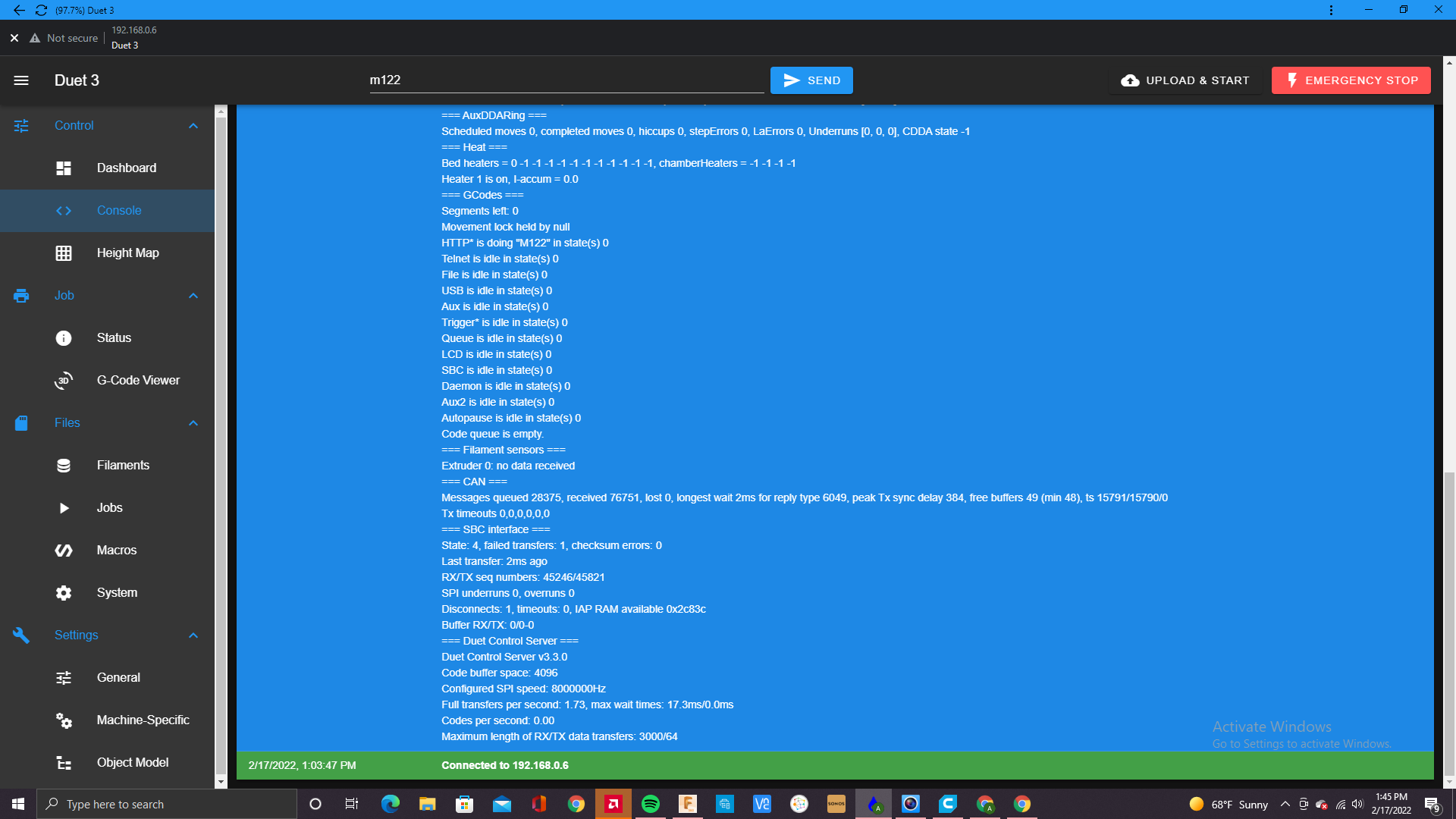
-
RE: Issue with filament monitor too little movementposted in Filament Monitor
@phaedrux ok thanks will try that.
-
RE: Issue with filament monitor too little movementposted in Filament Monitor
@dc42 ok thanks, what could be causing the "too little movement" fault to appear?
-
Issue with filament monitor too little movementposted in Filament Monitor
Machine pauses due to “too little movement” fault.
Duet 3 DWC 3.3.0
Filament ptfe tube is long so it’s causing a bit of resistance but was working for 3 layers of the print and I was able to print a small object just fine, then this happened. I’m not sure what’s going on or what is causing this, I just finished calibrating the filament sensor before I began the print job so it wasn’t the calibration I think.
I did send a new m591 to update the old one during the print and then sent a “m591 d0” to verify the change which is in the screenshot.
I’m not sure what the over 11131mm means in the console message?
Here’s my gcode
Time) ; General preferences G90 ; send absolute coordinates... M83 ; ...but relative extruder moves M550 P"Duet 3" ; set printer name ; Wait a moment for the CAN expansion boards to start G4 S2 ; Network ;M552 P0.0.0.0 S1 ; enable network and acquire dynamic address via DHCP ;M586 P0 S1 ; enable HTTP ;M586 P1 S0 ; disable FTP ;M586 P2 S0 ; disable Telnet ; Drives M569 P1.2 S1 ; X axis physical drive 0.4 goes forwards M569 P2.2 S1 ; X axis physical drive 0.5 goes forwards M569 P2.0 S1 ; Y axis physical drive 2.0 goes forwards M569 P2.1 S1 ; Y axis physical drive 2.1 goes forwards M569 P1.1 S0 ; Y axis physical drive 1.1 goes forwards M569 P1.0 S0 ; Y axis physical drive 1.3 goes backwards M569 P0.0 S1 ; Z axis physical drive 0.0 goes forwards M569 P0.1 S1 ; Z axis physical drive 0.1 goes forwards M569 P0.2 S1 ; Z axis physical drive 0.2 goes forwards M569 P0.3 S1 ; Z axis physical drive 0.3 goes forwards M569 P20.0 S0 ; Tool 1 physical drive 20.0 goes forwards M569 P21.0 S1 ; Tool 2 physical drive 21.0 goes forwards M569 P0.4 S0 ; Tool 2 physical drive 0.4 goes forwards M569 P0.5 S0 ; Tool changer coupler Physical drive 0.5 goes forwards M584 X1.2:2.2 Y2.0:2.1:1.1:1.0 Z0.0:0.1:0.2:0.3 C0.5 E20.0:21.0:0.4 ; Four Z motors connected to driver outputs Z axis M671 X-30:-30:890:890 Y-30:890:890:-30 S3 ; leadscrews at rear left, front left, front right, rear right (connected to Z) M208 X0:820 Y0:820 Z0:800 C0:360 ; X axis moves from 0 to 845, Y axis goes from 0 to 840, Z Moves from 0 to 800, C moves from -45 to 360 M350 X16 Y16 Z16 C16 E16:16:16 I1 ; configure microstepping with interpolation M92 X80.00 Y160.00 Z3200.00 C91.022 E837.00:837.00:760.00 ; set steps per mm M566 X200.00 Y200.00 Z270.00 C2 E7000.00:7000.00:7000.00 ; set maximum instantaneous speed changes (mm/min) M203 X7250.00 Y7250.00 Z350.00 C5000 E10000.00:10000.00:10000.00 ; set maximum speeds (mm/min) M201 X90.00 Y90.00 Z270.00 C500 E8000.00:8000.00:8000.00 ; set accelerations (mm/s^2) M906 X3500 Y2100 Z2300 C600 E990:990:500 I30 ; set motor currents (mA) and motor idle factor in per cent M84 S30 ; Set idle timeout ; Axis Limits ;M208 X0:845 Y0:890 Z0:800 C0:360 ; X axis moves from 0 to 845, Y axis goes from 0 to 840, Z Moves from 0 to 800, C moves from -45 to 360 ; Filament sensors M591 D0 P3 C"20.io1.in" S1 R82:131 L27.47 E30.0 ; Duet3D rotating magnet sensor for extruder drive 0 is connected to E0 endstop input, enabled, sensitivity 24.8mm.rev, 80% to 135% tolerance, 5mm detection length ;M591 D1 P1 C"21.io1.in" S1 ; filament monitor connected to pin 21.io1.in ;M591 D0 P1 C"0.io0.in" S1 ; filament monitor connected to pin 3.io3.in ;Extra sensor M308 S10 Y"mcu-temp" A"MCU" ; Endstops M574 X1 S1 P"2.io2.in" ; configure active-low endstop for low end on X via pin 2.io2.in M574 Y1 S1 P"1.io2.in" ; configure active-low endstop for low end on Y via pin 1,io2.in M574 C0 Z0 ; No C Z endstop ; Z-Probe M558 P8 C"!21.io0.in" H3 F150 ; set Z probe type to unmodulated and the dive height + speeds G31 P500 X0 Y0 Z1.28 ; set Z probe trigger value, offset and trigger height M557 X0:800 Y0:800 S65 ; define mesh grid X/Y and probe spacing ; Heaters M308 S0 P"temp0" Y"thermistor" A"Bed" T100000 B3950 ; configure Bed sensor 1 as thermistor on pin temp0 M950 H0 C"out0" T0 ; create bed heater output on out0 and map it to sensor 1 M307 H0 R0.224 C219.6 D7.78 S1.00 V24.1 ; PID auto tune results for Tool 1 bed heater M140 H0 ; map heated bed to heater 1 M143 H0 S120 ; set temperature limit for heater 1 to 120C M308 S1 P"20.temp0" Y"pt1000" A"Tool 0" ; configure sensor 0 as thermistor on pin 20.temp0 M950 H1 C"20.out0" T1 ; create nozzle heater output on 20.out0 and map it to sensor 0 M307 H1 B0 R1.519 C243.6 D3.15 S1.00 V22.7 ; PID auto tune results for Tool 0 Titan Aqua 1.75 ;M308 S2 P"21.temp0" Y"pt1000" A"Tool 1" ; configure sensor 0 as thermistor on pin 20.temp0 ;M950 H2 C"21.out0" T2 ; create nozzle heater output on 20.out0 and map it to sensor 0 ;M307 H2 B0 R1.717 C105.7:98.6 D2.95 S1.00 V23.9 ; PID auto tune results for Tool 0 Titan Aqua 1.75 ;fan M950 F0 C"out8" Q250 ; create fan 0 on pin out8 and set its frequency M106 P0 T115 S0.10 H1:2 C"Radiator Fan" ; set fan 0 value. Thermostatic control is turned on M950 F1 C"20.out2" Q250 ; create fan 1 on pin 20.out2 and set its frequency M106 P1 T205 S0.10 H1 C"Titan Aqua 1.75 T1 Hot end Fan" ; set fan 1 value. Thermostatic control is turned on M950 F2 C"21.out2" Q250 ; create fan 2 on pin 21.out2 and set its frequency M106 P2 T205 S0.10 H2 C"Titan Aqua 1.75 T2 support material Fan" ; set fan 2 value. Thermostatic control is turned on M950 F3 C"out5" Q250 ; create fan 3 on pin out5 and set its frequency ; Tools M563 P0 S"Titan Aqua 1.75" D0:2 H1 F0:1 ; define tool 0 M567 P0 E1.00:1.00 ; Mix drive E0 and drive E2 G10 P0 X0 Y0 Z0 ; set tool 0 axis offsets G10 P0 R0 S0 ; set initial tool 1 active and standby temperatures to 0C M563 P1 S"Titan Aqua 1.75 support" D1 H2 F0:2 ; define tool 1 G10 P1 X-15.4 Y0 Z0 ; set tool 2 axis offsets G10 P1 R0 S0 ; set initial tool 1 active and standby temperatures to 0C image url)
 -
RE: printer doesn't pause when there is a heater faultposted in General Discussion
@phaedrux ok thanks for the help. I'll order a duet filament sensor to monitor filament issues for now until this is fixed.
-
printer doesn't pause when there is a heater faultposted in General Discussion
My printer was almost done with a print and the heater fault was displayed but continued printing with out filament extruding because the heaters were at 0 Celsius. I was trying to figure out how to activate the auto pause when heater fault is displayed but could not figure out what was needed. Any help would be appreciated. I'm currently recalibrating heater so will update that but heater fault should cause printer to pause right? Thanks for the help in advance.
Duet 3 and DWC 3.3.0
; General preferences G90 ; send absolute coordinates... M83 ; ...but relative extruder moves M550 P"Duet 3" ; set printer name ; Wait a moment for the CAN expansion boards to start G4 S2 ; Network ;M552 P0.0.0.0 S1 ; enable network and acquire dynamic address via DHCP ;M586 P0 S1 ; enable HTTP ;M586 P1 S0 ; disable FTP ;M586 P2 S0 ; disable Telnet ; Drives M569 P1.2 S1 ; X axis physical drive 0.4 goes forwards M569 P2.2 S1 ; X axis physical drive 0.5 goes forwards M569 P2.0 S1 ; Y axis physical drive 2.0 goes forwards M569 P2.1 S1 ; Y axis physical drive 2.1 goes forwards M569 P1.1 S0 ; Y axis physical drive 1.1 goes forwards M569 P1.0 S0 ; Y axis physical drive 1.3 goes backwards M569 P0.0 S1 ; Z axis physical drive 0.0 goes forwards M569 P0.1 S1 ; Z axis physical drive 0.1 goes forwards M569 P0.2 S1 ; Z axis physical drive 0.2 goes forwards M569 P0.3 S1 ; Z axis physical drive 0.3 goes forwards M569 P20.0 S0 ; Tool 1 physical drive 20.0 goes forwards M569 P21.0 S1 ; Tool 2 physical drive 21.0 goes forwards M569 P0.4 S0 ; Tool 2 physical drive 0.4 goes forwards M569 P0.5 S0 ; Tool changer coupler Physical drive 0.5 goes forwards M584 X1.2:2.2 Y2.0:2.1:1.1:1.0 Z0.0:0.1:0.2:0.3 C0.5 E20.0:21.0:0.4 ; Four Z motors connected to driver outputs Z axis M671 X-30:-30:890:890 Y-30:890:890:-30 S3 ; leadscrews at rear left, front left, front right, rear right (connected to Z) M208 X0:820 Y0:820 Z0:800 C0:360 ; X axis moves from 0 to 845, Y axis goes from 0 to 840, Z Moves from 0 to 800, C moves from -45 to 360 M350 X16 Y16 Z16 C16 E16:16:16 I1 ; configure microstepping with interpolation M92 X80.00 Y160.00 Z3200.00 C91.022 E837.00:837.00:760.00 ; set steps per mm M566 X70.00 Y70.00 Z270.00 C2 E7000.00:7000.00:7000.00 ; set maximum instantaneous speed changes (mm/min) M203 X7250.00 Y7250.00 Z350.00 C5000 E10000.00:10000.00:10000.00 ; set maximum speeds (mm/min) M201 X90.00 Y90.00 Z270.00 C500 E8000.00:8000.00:8000.00 ; set accelerations (mm/s^2) M906 X3200 Y1800 Z2300 C600 E990:990:500 I30 ; set motor currents (mA) and motor idle factor in per cent M84 S30 ; Set idle timeout ; Axis Limits ;M208 X0:845 Y0:890 Z0:800 C0:360 ; X axis moves from 0 to 845, Y axis goes from 0 to 840, Z Moves from 0 to 800, C moves from -45 to 360 ; Filament sensors M591 D0 P1 C"20.io1.in" S1 ; filament monitor connected to pin 20.io1.in ;M591 D1 P1 C"21.io1.in" S1 ; filament monitor connected to pin 21.io1.in ;M591 D0 P1 C"0.io3.in" S1 ; filament monitor connected to pin 3.io3.in ;Extra sensor M308 S10 Y"mcu-temp" A"MCU" ; Endstops M574 X1 S1 P"2.io2.in" ; configure active-low endstop for low end on X via pin 2.io2.in M574 Y1 S1 P"1.io2.in" ; configure active-low endstop for low end on Y via pin 1,io2.in M574 C0 Z0 ; No C Z endstop ; Z-Probe M558 P8 C"!21.io0.in" H3 F150 ; set Z probe type to unmodulated and the dive height + speeds G31 P500 X0 Y0 Z1.28 ; set Z probe trigger value, offset and trigger height M557 X0:800 Y0:800 S65 ; define mesh grid X/Y and probe spacing ; Heaters M308 S0 P"temp0" Y"thermistor" A"Bed" T100000 B3950 ; configure Bed sensor 1 as thermistor on pin temp0 M950 H0 C"out0" T0 ; create bed heater output on out0 and map it to sensor 1 M307 H0 R0.224 C219.6 D7.78 S1.00 V24.1 ; PID auto tune results for Tool 1 bed heater M140 H0 ; map heated bed to heater 1 M143 H0 S120 ; set temperature limit for heater 1 to 120C M308 S1 P"20.temp0" Y"pt1000" A"Tool 0" ; configure sensor 0 as thermistor on pin 20.temp0 M950 H1 C"20.out0" T1 ; create nozzle heater output on 20.out0 and map it to sensor 0 M307 H1 B0 R1.858 C109.4 D2.96 S1.00 V23.6 ; PID auto tune results for Tool 0 Titan Aqua 1.75 ;M308 S2 P"21.temp0" Y"pt1000" A"Tool 1" ; configure sensor 0 as thermistor on pin 20.temp0 ;M950 H2 C"21.out0" T2 ; create nozzle heater output on 20.out0 and map it to sensor 0 ;M307 H2 B0 R1.717 C105.7:98.6 D2.95 S1.00 V23.9 ; PID auto tune results for Tool 0 Titan Aqua 1.75 ;fan M950 F0 C"out8" Q250 ; create fan 0 on pin out8 and set its frequency M106 P0 T115 S0.10 H1:2 C"Radiator Fan" ; set fan 0 value. Thermostatic control is turned on M950 F1 C"20.out2" Q250 ; create fan 1 on pin 20.out2 and set its frequency M106 P1 T205 S0.10 H1 C"Titan Aqua 1.75 T1 Hot end Fan" ; set fan 1 value. Thermostatic control is turned on M950 F2 C"21.out2" Q250 ; create fan 2 on pin 21.out2 and set its frequency M106 P2 T205 S0.10 H2 C"Titan Aqua 1.75 T2 support material Fan" ; set fan 2 value. Thermostatic control is turned on M950 F3 C"out5" Q250 ; create fan 3 on pin out5 and set its frequency ; Tools M563 P0 S"Titan Aqua 1.75" D0:2 H1 F0:1 ; define tool 0 M567 P0 E1.00:1.00 ; Mix drive E0 and drive E2 G10 P0 X0 Y0 Z0 ; set tool 0 axis offsets G10 P0 R0 S0 ; set initial tool 1 active and standby temperatures to 0C M563 P1 S"Titan Aqua 1.75 support" D1 H2 F0:2 ; define tool 1 G10 P1 X-15.4 Y0 Z0 ; set tool 2 axis offsets G10 P1 R0 S0 ; set initial tool 1 active and standby temperatures to 0C ; Custom settings are not defined T0 ; select first tool -
RE: Issue with Duet 3 6hcposted in General Discussion
@dc42 thanks for the help, that fixed my problem. If I need more fans connected for example to cool the steppers, is it ok to connect them to the expansion boards?
-
RE: Issue with Duet 3 6hcposted in General Discussion
@jay_s_uk hahaha, its pretty cold where I'm at but the reading is off because tool 1 is not in use and temp sensor isn't connected. As for the board picture, this is the best I can do now because its still connected. Two days ago I had the same issue and I turned it off and turned it back on 3 to 5 times and it showed the idle status which I thought was just a glitch of some sort because it showed 12v as well after doing so but in this case I haven't been able to do the same.

-
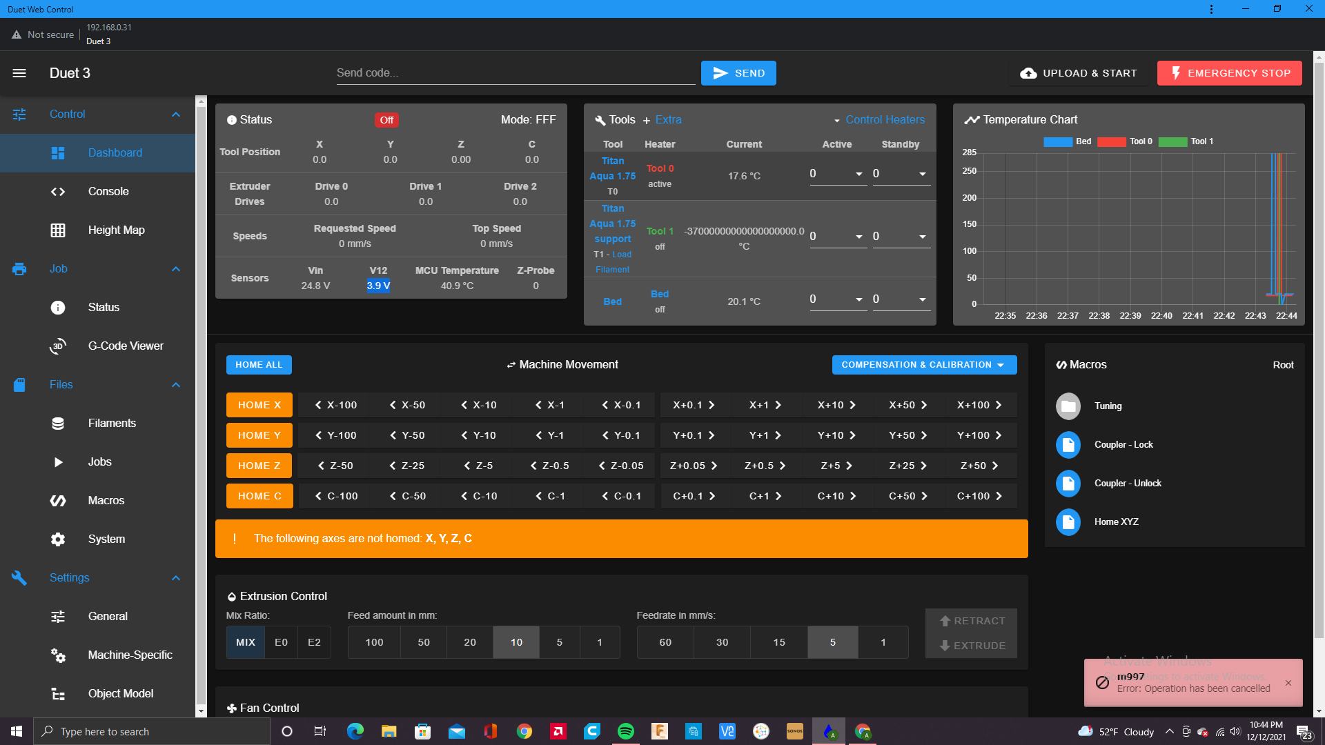
Issue with Duet 3 6hcposted in General Discussion
So, the issue that is occurring is that after turning my machine off for several days and it not being in use, I turn it back on and the duet says it off? which is weird because all the lights are on and everything is blinking as it should(before it would say its idled).Also the Voltage for the 12v is low and i think there may be something wrong there. I'm confused because this is recent and has only happened within the past month out of 1 year and a half since I purchased my duet 3. Id like to get this machine running again and any help would be appreciated. thanks.
-
tool board connectivityposted in Duet Hardware and wiring
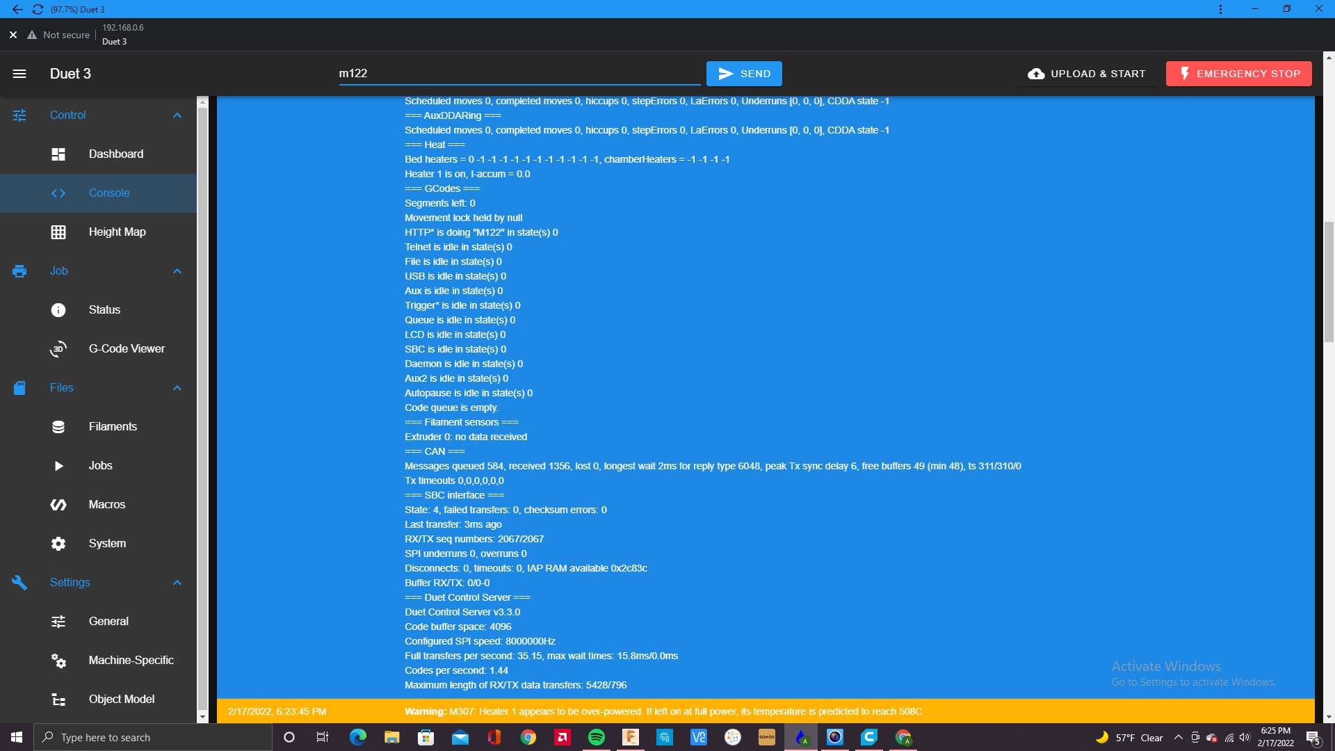
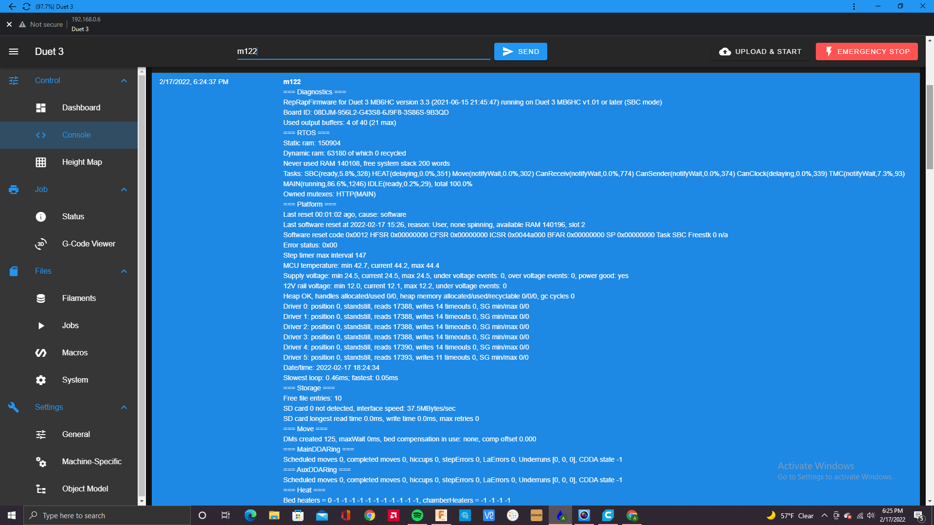
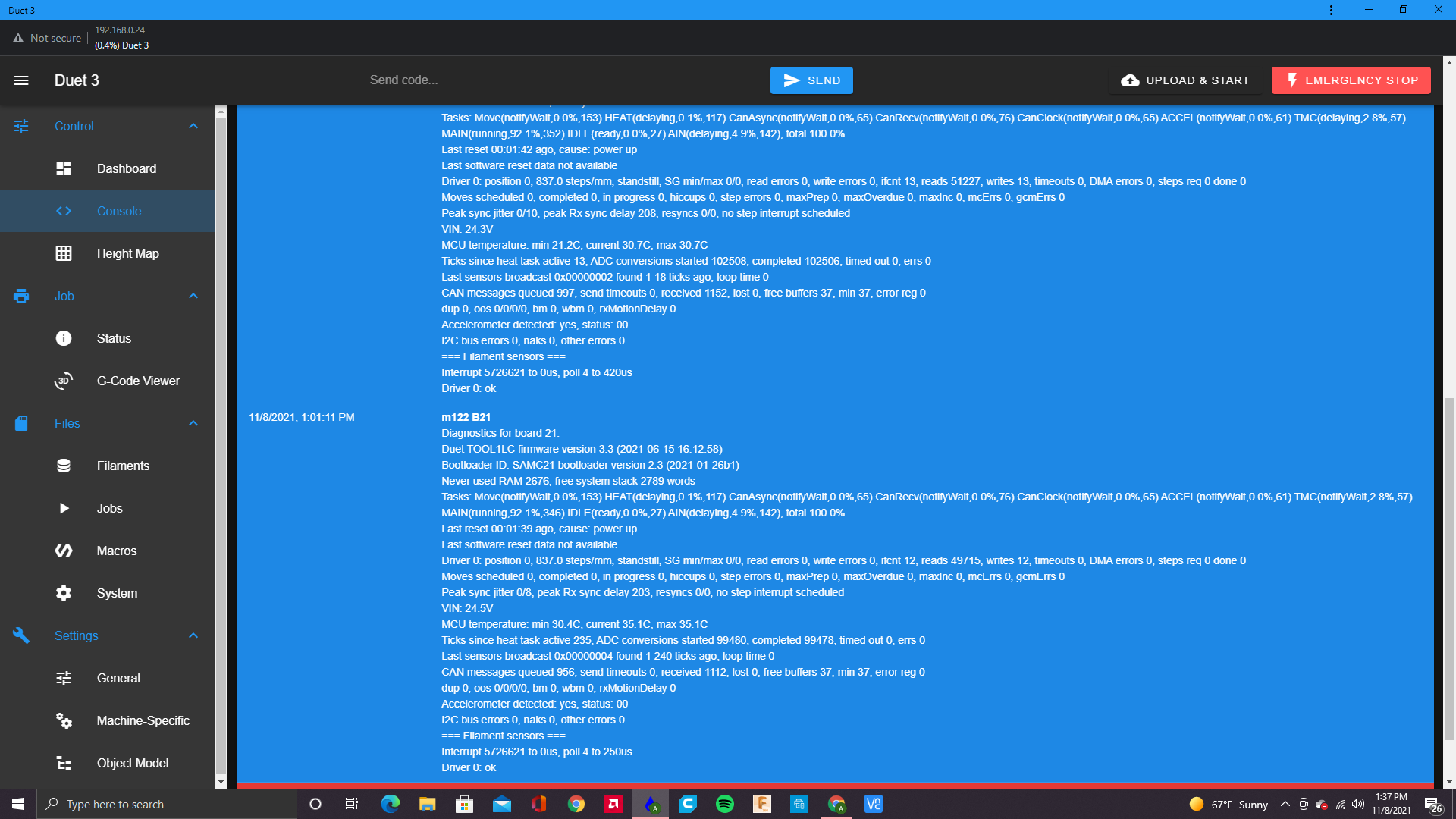
Connectivity issue with tool board. My printer was doing a job and in the middle of the print the tool board for the second extruder began to send error messages saying that there was connectivity issues. I ended up swapping out the tool board with one of the other tool boards I have on the machine and now it works. I'm not sure if this is due to the tool board itself or firmware issue. I sent the m122 to the tool board that I was having issues with and below were the results. it seems like its fine but when the printer would home and deploy the z probe it would send the the error message of :z probe not connected", after trying to restart the print. The board doesn't look damaged and I'm not sure what's wrong with it.


-
Future changes to limitations for filament sensor configurationposted in Firmware wishlist
Somethings I would like to be able to do using a basic filament runout sensor.
I'm looking into having a duet Magnetic filament sensor( M591 D0 P3 C"20.io1.in" S1) near the extruder connected to the tool board mainly for detecting precise filament movement and the other one, a Dyzen filament sensor(M591 D0 P1 C"0.io3.in" S1) that only detects filament runout as a back up sensor at the other end of the long Bowden tube. The dozuki page of limitations show that this option will not be supported. I understand that "Filament monitors must be connected to the same board as the corresponding extruder motor. This use so that the firmware can correlate the measured filament movement and the commanded extruder movement in real time." to avoid any miss reading but I just need the filament runout sensor at the other end of the Bowden tube to alert me if the filament just runs out(nothing to do with filament movement readings) that's what i would have the duet magnetic sensor for mainly. I understand the Duet magnetic sensor could do the same and i could run the Dyzen runout sensor wires to the tool board but id like to avoid having so many wires running from inside to outside the printers chamber.
If i can just configure a simple sensor to detect runout on an extruder running on a separate board that uses P1 that would be great. besides that the duet hardware and software is great. Thanks for all the help aswell.
-
RE: Configuring tool board(Push Pull) remote extruder Issueposted in Using Duet Controllers
@dc42 Here's the response I got, looks like all boards are running on the same firmware.
m115 b20
Duet TOOL1LC firmware version 3.3 (2021-06-15 16:12:58)m115 b21
Duet TOOL1LC firmware version 3.3 (2021-06-15 16:12:58)m115 b1
Duet EXP3HC firmware version 3.3 (2021-06-15 16:12:41)m115 b2
Duet EXP3HC firmware version 3.3 (2021-06-15 16:12:41)m115 b0
FIRMWARE_NAME: RepRapFirmware for Duet 3 MB6HC FIRMWARE_VERSION: 3.3 ELECTRONICS: Duet 3 MB6HC v1.01 or later FIRMWARE_DATE: 2021-06-15 21:45:56 -
RE: Configuring tool board(Push Pull) remote extruder Issueposted in Using Duet Controllers
@o_lampe The steps are different due to the gear ratios being different on each motor. I was going to try to run the motors on the same driver that's on the tool board but I just didn't want to run the wires from the tool board that's on the extruder to the remote stepper motor and have extra wires running from inside the print chamber. Also the peace of mind knowing I wont push the driver on the tool board too hard, which is something I didn't want to worry about since it can only use up to 1.6A. but good point I did consider that.
-
Configuring tool board(Push Pull) remote extruder Issueposted in Using Duet Controllers
I'm wondering if the issue I'm having is due to incorrect Gcode or if the duet software doesn't work with the configuration I'm trying to use on the 3HC boards. I have a tool board connected to tool 0 on driver 20.0 with a direct drive extruder and a remote stepper motor on the opposite end of the Bowden tube to push filament. I was configuring the remote stepper motor to driver 1.2(3HC board) and was having issues where it would seem to cause the y stepper motors(all y stepper motors are on the 3hc board) to become unsynchronized and they would begin to lose steps and make noise. I ended up switching the remote extruders driver from 1.2(3HC board) to 0.4 (Main Board) now its working but would like to add more remote stepper motors for other tools in the future. Can someone inform me on the software limitations, I couldn't find anything specifically on this. thanks.
; Configuration file for Duet 3 (firmware version 3.3) ; executed by the firmware on start-up ; ; generated by RepRapFirmware Configuration Tool v3.3.2 on Tue Sep 21 2021 11:41:45 GMT-0700 (Pacific Daylight Time) ; General preferences G90 ; send absolute coordinates... M83 ; ...but relative extruder moves M550 P"Duet 3" ; set printer name ; Wait a moment for the CAN expansion boards to start G4 S2 ; Network ;M552 P0.0.0.0 S1 ; enable network and acquire dynamic address via DHCP ;M586 P0 S1 ; enable HTTP ;M586 P1 S0 ; disable FTP ;M586 P2 S0 ; disable Telnet ; Drives M569 P1.2 S0 ; X axis physical drive 0.4 goes forwards M569 P2.2 S0 ; X axis physical drive 0.5 goes forwards M569 P2.0 S0 ; Y axis physical drive 2.0 goes forwards M569 P2.1 S0 ; Y axis physical drive 2.1 goes forwards M569 P1.1 S1 ; Y axis physical drive 1.1 goes forwards M569 P1.0 S1 ; Y axis physical drive 1.3 goes backwards M569 P0.0 S0 ; Z axis physical drive 0.0 goes forwards M569 P0.1 S0 ; Z axis physical drive 0.1 goes forwards M569 P0.2 S0 ; Z axis physical drive 0.2 goes forwards M569 P0.3 S0 ; Z axis physical drive 0.3 goes forwards M569 P20.0 S0 ; Tool 1 physical drive 20.0 goes forwards M569 P21.0 S1 ; Tool 2 physical drive 21.0 goes forwards M569 P0.4 S0 ; Tool 2 physical drive 21.0 goes forwards M584 X1.2:2.2 Y2.0:2.1:1.1:1.0 Z0.0:0.1:0.2:0.3 E20.0:21.0:0.4 ; Four Z motors connected to driver outputs Z axis M671 X-30:-30:890:890 Y-30:1150:1150:-30 S3 ; leadscrews at rear left, front left, front right, rear right (connected to Z) M208 X0:845 Y0:890 ; X carriage moves from 0 to 870, Y bed goes from 0 to 870 M350 X4 Y4 Z16 E16:16:16 I1 ; configure microstepping with interpolation M92 X40.00 Y40.00 Z3200.00 E837.00:837.00:830.00 ; set steps per mm M566 X110 Y110 Z270.00 E7000.00:7000.00:7000.00 ; set maximum instantaneous speed changes (mm/min) M203 X7250.00 Y7250.00 Z350.00 E10000.00:10000.00:10000.00 ; set maximum speeds (mm/min) M201 X115.00 Y115.00 Z290.00 E8000.00:8000.00:8000.00 ; set accelerations (mm/s^2) M906 X2500 Y2500 Z2100 E550:550:550 I20 ; set motor currents (mA) and motor idle factor in per cent M84 S20 ; Set idle timeout ; Axis Limits M208 X0 Y0 Z0 S1 ; set axis minima M208 X845 Y890 Z780 S0 ; set axis maxima ; Filament sensors M591 D0 P1 C"20.io1.in" S1 ; filament monitor connected to pin 121.io1 M591 D1 P1 C"21.io1.in" S1 ; filament monitor connected to pin 121.io1 ;Extra sensor M308 S10 Y"mcu-temp" A"MCU" ; Endstops M574 X1 S1 P"2.io2.in" ; configure active-low endstop for low end on X via pin 2.io2.in M574 Y1 S1 P"1.io2.in" ; configure active-low endstop for low end on Y via pin 1,io2.in ; Z-Probe M558 P8 C"!21.io0.in" H3 F300 ; set Z probe type to unmodulated and the dive height + speeds G31 P500 X0 Y0 Z-0.28 ; set Z probe trigger value, offset and trigger height M557 X60:820 Y60:820 S65 ; define mesh grid X/Y and probe spacing ; Heaters M308 S0 P"temp0" Y"thermistor" A"Bed" T100000 B3950 ; configure Bed sensor 1 as thermistor on pin temp0 M950 H0 C"out0" T0 ; create bed heater output on out0 and map it to sensor 1 M307 H0 R0.224 C219.6 D7.78 S1.00 V24.1 ; PID auto tune results for Tool 1 bed heater M140 H0 ; map heated bed to heater 1 M143 H0 S120 ; set temperature limit for heater 1 to 120C M308 S1 P"20.temp0" Y"pt1000" A"Tool 0" ; configure sensor 0 as thermistor on pin 20.temp0 M950 H1 C"20.out0" T1 ; create nozzle heater output on 20.out0 and map it to sensor 0 M307 H1 B0 R1.858 C109.4 D2.96 S1.00 V23.6 ; PID auto tune results for Tool 0 Titan Aqua 1.75 M308 S2 P"21.temp0" Y"pt1000" A"Tool 1" ; configure sensor 0 as thermistor on pin 20.temp0 M950 H2 C"21.out0" T2 ; create nozzle heater output on 20.out0 and map it to sensor 0 M307 H2 B0 R1.717 C105.7:98.6 D2.95 S1.00 V23.9 ; PID auto tune results for Tool 0 Titan Aqua 1.75 ;fan M950 F0 C"out8" Q250 ; create fan 0 on pin out8 and set its frequency M106 P0 T115 S0.10 H1:2 C"Radiator Fan" ; set fan 0 value. Thermostatic control is turned on M950 F1 C"20.out2" Q250 ; create fan 1 on pin out9 and set its frequency M106 P1 T205 S0.10 H1 C"Titan Aqua 1.75 T1 Hot end Fan" ; set fan 1 value. Thermostatic control is turned on M950 F2 C"21.out2" Q250 ; create fan 0 on pin out8 and set its frequency M106 P2 T205 S0.10 H2 C"Titan Aqua 1.75 T2 support material Fan" ; set fan 0 value. Thermostatic control is turned on ; Tools M563 P0 S"Titan Aqua 1.75" D0:2 H1 F0:1 ; define tool 0 M567 P0 E1.00:1.00 ; Mix drive E0 and drive E2 G10 P0 X0 Y0 Z0 ; set tool 0 axis offsets G10 P0 R0 S0 ; set initial tool 1 active and standby temperatures to 0C M563 P1 S"Titan Aqua 1.75 support" D1 H2 F0:2 ; define tool 1 G10 P1 X-15.4 Y0 Z0 ; set tool 2 axis offsets G10 P1 R0 S0 ; set initial tool 1 active and standby temperatures to 0C ; Custom settings are not defined T0 ; select first tool -
Any future updates for 1xd and 3hc expansion boards?posted in Hardware wishlist
Will there be updates for the 1xd and 3hc boards? I’m in need of higher voltage than the max 48v for 1xd and 32v for 3hc.
-
RE: RRF v3.3/Mini 5+ Wifi - Major problems with layer shiftingposted in Using Duet Controllers
@gixxerfast I wonder if replacing the PSU with a higher Voltage (36v-48v) would help? I have this problem on my corexy and can only print at 60mm/s which is slow compared to what other printers can do. I'm also using 0.9 degree motors. I'm thinking of doing what you did and changing the motors to 1.8 deg motors. this post was helpful.