@siam I was also missing the motor mapping assignment, which is a big bad omission. I was wondering why my Z-tower motor was in whining fibrillation mode for 30 seconds after a reset.
Posts made by shadowphile
-
RE: Duet Ethernet won't detect my new accelerometer board.posted in Duet Hardware and wiring
-
RE: Duet Ethernet won't detect my new accelerometer board.posted in Duet Hardware and wiring
@siam I finally got it all working!
The issue was the assignment I used from the documentation: M955 P0 C"spi.cs4+spi.cs3". I swapped the 3 and 4 and it all started working. Short jumpers to the sensor worked ok but I need to refine my cabling because bouncing on my CS edges is causing random acquisition failures.
But otherwise I think I'm good, thanks for the help. -
RE: Duet Ethernet won't detect my new accelerometer board.posted in Duet Hardware and wiring
@siam config.g file is attached to the first post.
M98 reports 'Warning: Macro file 0 not found"
Cable is about 170 cm long. 3 twisted shielded pairs, shielding connected to ground on all. I did somehow route SD0 and CS in the same twisted pair. My bad, but it does not explain the lack of ANY activity on the CS3 or CS4 (even a terrible connection should show the first (messy attempt) to talk to the board before giving up. -
RE: Duet Ethernet won't detect my new accelerometer board.posted in Duet Hardware and wiring
@siam That is what I did. The lack of signals on CS3 and CS4 were measured on the Input connector. Check my wiring (pictures and text description of cable routing) in case I am wrong somehow.
Also still have that problem with heaters not showing up on the dashboard. -
Duet Ethernet won't detect my new accelerometer board.posted in Duet Hardware and wiring
At Crocker's suggestion this is a repost from the RepRap forum:
I've been following the instructions to set up an Adafruit LIS3DH accelerometer on my DuetEthernet. I've been running 3.3 up till now, then installed 3.4b3. I have a temp daughterboard so made my cable according to that (see pics).
When I manually attempt to run M955 P0 C"spi.cs4+spi.cs3" S1000 to set up an accelerometer, I get 'accelerometer not found on specified port'.
After double-checking my wire routing, I put an oscilloscope on all the pins of the temp daughterboard's Output connector. There is regular bus data going on, including activity on CS1 and CS2 when the PT100 sensors are read. But CS3 and CS4 don't change when I send the M995 command. I hope my Duet board isn't damaged! It might be the firmware, see below.
Pictures can't show everything clearly so here is my cable mapping. There are three separate shielded cables. They all share ground but only connect to gnd on the Duet side to prevent ground loops.
Duet Temp Daughterboard Output Connector -> Pin names on the accelerometer board:
1 - INT
2 - GND
3 - CS
4 - SCL
5 - SDA
6 - SDO
8 - Vin


Related problems:
...3.4b3 web control is not showing either tool on the dashboard, just the bed. the temp graph however has three heaters in the legend (I have a dual extruder).Config.g file is attached. Below is the diagnostic report form the Duet board.
M122
=== Diagnostics ===
RepRapFirmware for Duet 2 WiFi/Ethernet version 3.3 (2021-06-15 21:44:54) running on Duet Ethernet 1.02 or later
Board ID: 08DGM-9T6BU-FG3SN-6JKDD-3SN6J-TVWHG
Used output buffers: 3 of 24 (15 max)
=== RTOS ===
Static ram: 23876
Dynamic ram: 69888 of which 584 recycled
Never used RAM 20068, free system stack 150 words
Tasks: NETWORK(ready,26.0%,231) HEAT(delaying,0.1%,330) Move(notifyWait,0.1%,317) MAIN(running,73.9%,503) IDLE(ready,0.0%,29), total 100.0%
Owned mutexes:
=== Platform ===
Last reset 01:05:09 ago, cause: software
Last software reset at 2021-09-10 21:02, reason: User, GCodes spinning, available RAM 20308, slot 2
Software reset code 0x0003 HFSR 0x00000000 CFSR 0x00000000 ICSR 0x0041f000 BFAR 0xe000ed38 SP 0x00000000 Task MAIN Freestk 0 n/a
Error status: 0x00
Aux0 errors 0,0,0
Step timer max interval 0
MCU temperature: min 32.7, current 33.2, max 36.0
Supply voltage: min 24.1, current 24.3, max 24.3, under voltage events: 0, over voltage events: 0, power good: yes
Heap OK, handles allocated/used 0/0, heap memory allocated/used/recyclable 0/0/0, gc cycles 0
Driver 0: position 150194, standstill, SG min/max not available
Driver 1: position 150194, standstill, SG min/max not available
Driver 2: position 150194, standstill, SG min/max not available
Driver 3: position 0, standstill, SG min/max not available
Driver 4: position 0, standstill, SG min/max not available
Driver 5: position 0
Driver 6: position 0
Driver 7: position 0
Driver 8: position 0
Driver 9: position 0
Driver 10: position 0
Driver 11: position 0
Date/time: 2021-09-10 22:07:28
Cache data hit count 4294967295
Slowest loop: 22.02ms; fastest: 0.17ms
I2C nak errors 0, send timeouts 0, receive timeouts 0, finishTimeouts 0, resets 0
=== Storage ===
Free file entries: 10
SD card 0 detected, interface speed: 20.0MBytes/sec
SD card longest read time 2.0ms, write time 8.7ms, max retries 0
=== Move ===
DMs created 83, maxWait 171ms, bed compensation in use: none, comp offset 0.000
=== MainDDARing ===
Scheduled moves 1, completed moves 1, hiccups 130458, stepErrors 0, LaErrors 0, Underruns [0, 0, 0], CDDA state -1
=== AuxDDARing ===
Scheduled moves 0, completed moves 0, hiccups 0, stepErrors 0, LaErrors 0, Underruns [0, 0, 0], CDDA state -1
=== Heat ===
Bed heaters = 0 -1 -1 -1, chamberHeaters = -1 -1 -1 -1
=== GCodes ===
Segments left: 0
Movement lock held by null
HTTP is idle in state(s) 0
Telnet is idle in state(s) 0
File is idle in state(s) 0
USB is idle in state(s) 0
Aux is idle in state(s) 0
Trigger is idle in state(s) 0
Queue is idle in state(s) 0
LCD is idle in state(s) 0
Daemon is idle in state(s) 0
Autopause is idle in state(s) 0
Code queue is empty.
=== Network ===
Slowest loop: 66.95ms; fastest: 0.02ms
Responder states: HTTP(2) HTTP(2) HTTP(0) HTTP(0) FTP(0) Telnet(0), 0 sessions
HTTP sessions: 1 of 8
Interface state active, link 100Mbps full duplex -
RE: mis-assigned heaters (setting up multiple hotends)posted in Duet Hardware and wiring
@droftarts I fixed the channel assignments and disconnected heater 1. System still went into reset and looked like a short because all the PCB LEDs blank out the moment I select either T0 or H1 (GUI links), or send T0 by the console.
However, the heaters are working now and I've tuned them up already.
I tried a few more times with T0 or T1 though and haven't been able to force a reset. It would be great if it stayed this way!thanks
-
RE: mis-assigned heaters (setting up multiple hotends)posted in Duet Hardware and wiring
@droftarts thanks for the quick reply! Your reply had me scrambling for a while until I realized that T stands for Temperature sensor, not Tool.
-
RE: mis-assigned heaters (setting up multiple hotends)posted in Duet Hardware and wiring
oh, and when I try to select T1 the board seems to reset!
-
RE: mis-assigned heaters (setting up multiple hotends)posted in Duet Hardware and wiring
oops, I had a typo: here is the heater/sensor mis-match table:
heater 1 is reporting the bed sensor
heater 2 is reporting heater 1 sensor
bed is reporting the heater 2 sensor -
mis-assigned heaters (setting up multiple hotends)posted in Duet Hardware and wiring
I've been using one hotend for a long time with no problem. I just added a second one but the heaters don't line-up with the sensors now. I detach the sensor connection at hotend 1 but the 2nd hotend reports 2000deg. I detach the sensor from hotend 2 then the bed (H0) sensor reports 2000deg. I detach the bed sensor and heater 1 now reports a bad value.
Here's the tech info: followed by my config file:
Board: Duet 2 Ethernet (2Ethernet)
Firmware: RepRapFirmware for Duet 2 WiFi/Ethernet 3.2.2 (2021-02-11); Configuration file for Duet WiFi (firmware version 3.00) ; executed by the firmware on start-up ; ; generated by RepRapFirmware Configuration Tool v3.2.3 on Sat Mar 13 2021 14:27:17 GMT-0800 (Pacific Standard Time) ; modified to match older config file ; General preferences G90 ; send absolute coordinates... M83 ; ...but relative extruder moves M550 P"MDCDelta" ; set printer name M665 R247.3721 L450 B160 H384 X0 Y0 Z0 ; set delta radius, diagonal rod length, printable radius, homed height, and x,y, and z tower rotations. ;M666 X0 Y0 Z0 ; put your endstop adjustments here, or let auto calibration find them ; Network M552 S1 P192.168.1.15 ; enable network and force IP address M586 P0 S1 ; enable HTTP M586 P1 S0 ; disable FTP M586 P2 S0 ; disable Telnet ; Drives M569 P0 S1 ; physical drive 0 direction M569 P1 S0 ; physical drive 1 direction M569 P2 S0 ; physical drive 2 direction M569 P3 S0 ; physical drive 3 direction M569 P4 S0 ; physical drive 3 direction M584 X0 Y1 Z2 E3:4 ; set drive mapping M350 X16 Y16 Z16 E16:E16 I1 ; configure microstepping with interpolation M92 X200 Y200 Z200 E2700:2700 ; Set axis steps/mm These settings for Zesty Nimble extruder ; eSun Black PLA+ E2699 (at 1mm/sec thru .6mm nozzle) ; Hatchbox White PLA E2669 ; Proto-pasta Iron PLA E2669 ; Matteforge Gray E2776 (at 5mm/sec through .6mm nozzle) ; White PETG 2776 (at 5mm/sec through .6mm nozzle) ; Mika3D Silk Copper E2722 (at 5mm/sec through .6mm nozzle) ; PLA+ E2669 ; (at 5mm/sec through .4mm nozzle) ; Priline wood E2812 ; PLA 2638? (lots of pla prints at this setting but does not match the makerbot pla below) ; Ninjaflex: E2814 ; Botfeeder Filastic: E2777 ; NinjaTek Armadillo: E2666 ; Makerbot PLA: E2614 (includes all hard materials ie wood, stone, pla, hard nylons) ; Taulman PCTPE: E2614 M566 X700 Y700 Z400 E40:40 ; Maximum instant speed changes mm/minute M203 X19980.00 Y19980 Z15000 E1020:1020 ; set maximum speeds (mm/min) M201 X3000 Y3000 Z1000 E120:120 ; Accelerations (mm/s^2) (120 for zesty, 1000 normally) M906 X1000 Y1000 Z1000 E500:500 ; Set motor currents (mA) (500 for Zesty, 1200 normally) M84 S30 ; Set idle timeout ; Axis Limits M208 S1 Z-0.2 ; set minimum Z ; Endstops M574 S1 X2 P"xstop" M574 S1 Y2 P"ystop" M574 S1 Z2 P"zstop" ; Z-Probe M558 P5 C"z_probe.in" H5 F120 T3000 ; create z probe line and type G31 P500 X0 Y0 Z0 ; set Z probe trigger value, offset and trigger height M556 S50 X0 Y0 Z0 ; set orthogonal axis compensation parameters ;M557 R85 S20 ; define mesh grid ; temp sensors M308 S0 P"bed_temp" Y"thermistor" T100000 B4349 ;sets bed sensor type M308 S1 P"spi.cs1" Y"rtd-max31865" ;sets extruder 1 sensor type M308 S2 P"spi.cs2" Y"rtd-max31865" ;sets extruder 2 sensor type ; Heaters M950 H0 T2 C"bedheat" ;make bed heater M950 H1 T0 C"e0heat" ;make extruder #1 heater M950 H2 T1 C"e1heat" ;make extruder #2 heater M140 H0 ;assign bed heaters ; PID settings M307 H0 R0.517 C424 D4.49 S1.00 V24.2 ;from a run done on 3/13/2021 ; Limits M143 H0 S120 A2 ; temperature limit for bed to 120° M143 H1 S300 A2 ; set temperature limit for heater 1 to 300C M143 H2 S300 A2 ; set temperature limit for heater 2 to 300C ; Fans MM950 F0 C"fan0" M106 P0 S0 I0 F500 H-1 ; set fan 0 value, PWM signal inversion and frequency. Thermostatic control is turned off ; Tools M563 P0 D0 H1 ; define tool 0 (old: M563 P0 D0 H1) G10 P0 X-11 Y0 Z0 ; set tool 0 axis offsets G10 P0 R50 S50 ; set initial tool 0 active and standby temperatures to 0C M563 P1 D1 H2 ; define tool 1 G10 P1 X11 Y0 Z0 ; set tool 1 axis offset G10 P1 R60 S120 ; set initial tool 1 active and standby temperatures to 0C ; Custom settings are not defined M575 P1 B57600 S0 ; set serial port parameters for messages f ; Miscellaneous M501 ; load saved parameters from non-volatile memory -
RE: troubleshooting delta build with heightmappingposted in Tuning and tweaking
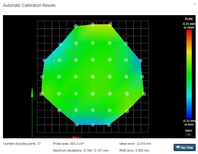
I think the lesson I learned is that the heightmap is a useful tool for troubleshooting mechanical problems, since any looseness will show up as shifts in Z. In my case the delta symmetry of the heightmap indicated a common problem with all three towers: the effector wasn't stable, loose screws.
In fact, even with a bed flat to .02rms, I still get a ghost of a delta pattern, interesting. -
RE: troubleshooting delta build with heightmappingposted in Tuning and tweaking
@Veti
-Interpolate: 'how did that get turned off?'. On the other hand, no seemed to change when enabled it.
-offset: my offset is about .5 and varies across the bed <.01.
-G30: 9-factor miraculously got me down to like .02mm rms. However, the rods are now tuned 4mm longer than the actual rods! Not comfortable with this. I also had to adjust the scale on x and y axes 1%. However, I saved it all with M500, then changed the G30 routine back to six-factor. There seem to be hidden variables that I shoved around because now six-factor still returns .02.
So I am good!G29 (Heightmapping):
does this just record the height at each spot and linearly interpolate between them? (after G30) Doesn't seem to improve my overall rms.No matter, I think I got it worked out; thought I might be in some major trouble there, whew! Consider this solved and thanks for the help!
-
RE: I want the exact profile (wrt to time) of my effector motion.posted in Tuning and tweaking
thanks for the reply!
Here is a web based analyzer that is accurate enough to include motion parameters like accel. https://www.gcodeanalyser.com/Otherwise, I guess I'm trying to get a real-time plot because I want to know WHEN I'm hitting limits. The weight of the mobile parts and the dynamic torque of the motors determine when those limits are reach but that isn't practical at all (and even harder with a delta).
But I it seems like without an external way to track the tip there is no way to know. And of course if you could do that, then you can close the control loop and get rid of calibration problems (almost) completely.A lot of concepts from the original reprap release were fine for the early days and cheap builds but as performance is increased some of those elements need to be revised. Closing the loop to get cheap but precise nozzle placement would be a big improvement and just eliminate most calibration issues. Easy to do with 3 encoders on a cartesian, much harder on a delta. Sometimes I wonder if my delta is worth the trouble. There's a reason most printers aren't deltas.
-
I want the exact profile (wrt to time) of my effector motion.posted in Tuning and tweaking
Any way to get this from the gcode or other method? It would help a lot knowing what my actual jerk,accel, and velocity emerges from a move. My theoretical upper speed on my delta (setting step rate of Duet at 50Khz, and .0003" step resolution) gives me an upper end of 380mm/sec, WAY faster than I can go. I just updated my machine with lighter parts and want to see the difference more than just "it prints faster".
(it occurs to me I can probably write a python script to analyze the gcode)
edit: there is no timing information in gcode so I guess that won't work since the time between each step is unknown) -
RE: troubleshooting delta build with heightmappingposted in Tuning and tweaking
@Phaedrux forgot to mention, my probe is a custom piezo design that detects the nozzle contact with the bed. It taps out pretty consistently (<.01mm). I even checked it in the extreme regions of the heightmap but still reliable.
-
RE: troubleshooting delta build with heightmappingposted in Tuning and tweaking
I poked around with updating recently but other things were higher priority once I found out heightmaps were already in my installed version. But thanks for the link!
Thanks for the link to the calibration too. I did run across it but none of the pictures matched my 'S' curve cross-section aligned with each tower, but I definitely should read it fully.
-
RE: troubleshooting delta build with heightmappingposted in Tuning and tweaking
thanks for the reply! I shorted the info since I figured somebody would look at the heightmap and immediately know what the problem could be.
But here are the files you requested. I was already following the second of your links about calibrating a delta printer but it doesn't help if the parts are designed wrong (or something like that).
I'm still have a lingering worry that my new design is too squishy. My system before was rock solid but the new effector is rather squishy when I push on it so I'm still studying where the actual deflections/play are occurring and whether they would influence the bed compensations.M122.txt config-override.g config.g bed.g -
troubleshooting delta build with heightmappingposted in Tuning and tweaking
I just finished a two year process of designing and upgrading my custom delta. It has a print volume of 350mm wide and about 400mm high at the center.
My leveling is a lot worse than before. It was usually .025mm rms with 9 points and now it's 0.1mm, ugh! Mesh bed correction only drops that down to about .05.
Interestingly though, the heightmap clearly reflects a delta configuration. That implies that the mechanics are trued up and the problem is something systemic like effector and/or carriages are too soft, or some system parameter is off! (my system was heavy and accurate but I designed lighter versions of all the moving parts. Perhaps too light )
)
thanks for considering my problem
-
RE: how to clear a bad AutoDeltaCalibration?posted in General Discussion
@PCR only after a successful calibration
-
RE: AIR PUMP USERS please chime in :)posted in General Discussion
@Dougal1957 The pumps I got off Amazon were way too weak but I trusted what you said and ordered that diaphragm pump because its so cheap! I have to run it through about 6 feet of narrow tubing (100cm high delta) so we will see if it can maintain enough airflow and pressure. My air-brush compressor, albeit WAY oversized, is super quiet and gobs of pressure/airflow.