@rjenkinsgb Thank you very much
That was a stupid mistake and I could not see it.
I fixed it
Posts made by sigourosandreas
-
RE: DWC not showing all toolsposted in General Discussion
-
RE: DWC not showing all toolsposted in General Discussion
@droftarts I did run the command and I got a chaos.
Is this possible? How should I change all these lines?
M98 p"config.g"
HTTP is enabled on port 80
FTP is disabled
TELNET is disabled
Error: in file macro line 30 column 25: M92: array too long, max length = 1
Error: in file macro line 33 column 10: M350: array too long, max length = 1
Error: in file macro line 34 column 25: M566: array too long, max length = 1
Error: in file macro line 35 column 32: M203: array too long, max length = 1
Error: in file macro line 36 column 28: M201: array too long, max length = 1
Error: in file macro line 38 column 11: M906: array too long, max length = 1
Error: Sensor number out of range
Error: Sensor number out of range
Error: bad drive number
Error: Tool 1 not found
Error: Tool 1 not found
Error: bad drive number
Error: Tool 2 not found
Error: Tool 2 not found
Error: Tool 1 not found
Error: Tool 2 not found -
RE: toolboard to match nema14 motorsposted in Hardware wishlist
Very nice project for those who knows electronics.
I am already using a 3 tool tolchanger and I am interested in upgrading it from duet2 to duet3 electronics.
If it was possible to make such a toolboard I would buy them and do the upgrade yesterday. -
DWC not showing all toolsposted in General Discussion
I am having a problem with DWC. It doesn't show all 3 tools. Only the first one is shown. I thing the config is correct. Please help me solve this.
I am using the followng:
Board: Duet 2 WiFi (2WiFi) + Duex5
Firmware: RepRapFirmware for Duet 2 WiFi/Ethernet 3.3 (2021-06-15)
Duet WiFi Server Version: 1.26
Duet Web Control 3.3.0Do not mind about the "T0" temperature. I don't have it connected at the moment.

This i part of my config file:
; Drives
M569 P6 S1 ; physical drive 6 goes backwards (X axis)
M569 P5 S1 ; physical drive 5 goes backwards (Y axis)
M569 P2 S1 ; physical drive 2 goes backwards (Z axis)
M569 P4 S1 ; physical drive 4 goes backwards (Coupler)
M569 P9 S0 ; physical drive 9 goes forwards (E0)
M569 P8 S1 ; physical drive 8 goes forwards (E1)
M569 P7 S1 ; physical drive 7 goes forwards (E2)
M584 X6 Y5 Z2 E9,8,7 C4 ; set drive mapping
M208 X-7.5:325 Y0:317 Z0:325 C0:400 ; Set axis minima & maxima
M92 X100.00 Y100.00 Z400.00 E655:655:655 C100.00 ; set steps per mm
M350 C8 I0 ; configure microstepping without interpolation
M350 X16 Y16 Z16 I1 ; configure microstepping with interpolation
M350 E16:16:16 I1 ; configure microstepping with interpolation
M566 X400 Y400 Z10 E300:300:300 C2 ; set maximum instantaneous speed changes (mm/min)
M203 X14500 Y14500 Z1000 E3600:3600:3600 C5000 ; set maximum speeds (mm/min)
M201 X4000 Y4000 Z400 E600:600:600 C500 ; set accelerations (mm/s^2)
M906 X1500 Y1500 Z1700 C500 I80 ; set motor currents (mA) and motor idle factor in per cent
M906 E700:700:700 I60 ; set motor currents (mA) and motor idle factor in per cent
M84 S120 ; Set idle timeout; Endstops
M574 X1 S1 P"xstop" ; configure endstop switch for low end on X
M574 Y1 S1 P"ystop" ; configure endstop switch for low end on Y
M574 Z0 C0 ; configure no Z, C endstop
M574 C1 S3 ; configure sensorless endstop for low end on C;Stall Detection
M915 C S5 R0 F0 H400 ; coupler; Z-Probe
M558 P8 C"zstop" H3 F360 I0 T20000 ; set Z probe type to switch, the axes for which it is used and the dive height + speeds
G31 P200 X-15.3 Y49.47 Z2.5 ; set Z probe trigger value, offset and trigger height
M557 X10:320 Y56:306 S62:50 ; define mesh grid; Heaters
M308 S0 P"bedtemp" Y"thermistor" A"Bed" T100000 B4725 C7.06e-8 ; configure sensor 0 as thermistor on pin bedtemp
M950 H0 C"bedheat" T0 ; create bed heater output on bedheat and map it to sensor 0
M307 H0 B0 R1.516 C290.1 D4.90 S1.00 V24.0 ; disable bang-bang mode for heater and set PWM limit
M140 H0 ; map heated bed to heater 0
M143 H0 S140 ; set temperature limit for heater 0 to 140CM308 S1 P"duex.e6temp" Y"thermistor" A"T0" T100000 B4725 C7.06e-8 ; configure sensor 1 as thermistor on pin duex.e6temp
M950 H1 C"e0heat" T1 ; create nozzle heater 7 output on duex.e6heat and map it to sensor 1
M307 H1 B0 S1 ; disable bang-bang mode for heater 7 and set PWM limit
M143 H1 S300 ; set temperature limit for heater 7 to 300CM308 S2 P"duex.e5temp" Y"thermistor" A"T1" T100000 B4725 C7.06e-8 ; configure sensor 2 as thermistor on pin e3temp
M950 H2 C"e1heat" T2 ; create nozzle heater output on e0heat and map it to sensor 2
M307 H2 B0 S1 ; disable bang-bang mode for heater and set PWM limit
M143 H2 S300 ; set temperature limit for heater 1 to 300CM308 S3 P"duex.e4temp" Y"thermistor" A"T2" T100000 B4725 C7.06e-8 ; configure sensor 2 as thermistor on pin e3temp
M950 H3 C"!duex.e2heat" T3 ; create nozzle heater output on e0heat and map it to sensor 2
M307 H3 B0 S1 ; disable bang-bang mode for heater and set PWM limit
M143 H3 S300 ; set temperature limit for heater 1 to 300C; Fans
M950 F1 C"duex.fan6" Q80 ; create fan 1 (print cooling fan) on pin fan6 and set its frequency
M106 P1 S0 H-1 ; set fan 3 value. Thermostatic control is turned offM950 F2 C"duex.fan3" Q80 ; create fan 2 (extruder0 fan) on pin fan3 and set its frequency
M106 P2 S1 H1 T60 ; set fan value. Thermostatic control is turned onM950 F3 C"fan1" Q80 ; create fan 3 (print cooling fan) on pin fan3 and set its frequency
M106 P3 S0 H-1 ; set fan 3 value. Thermostatic control is turned offM950 F4 C"duex.fan4" Q80 ; create fan 4 (extruder1 fan) on pin fan4 and set its frequency
M106 P4 S1 H2 T60 ; set fan value. Thermostatic control is turned onM950 F5 C"fan2" Q80 ; create fan 5 (print cooling fan) on pin fan3 and set its frequency
M106 P5 S0 H-1 ; set fan 3 value. Thermostatic control is turned offM950 F6 C"duex.fan5" Q80 ; create fan 6 (extruder2 fan) on pin fan1 and set its frequency
M106 P6 S1 H3 T60 ; set fan value. Thermostatic control is turned onM950 F7 C"duex.fan8" T"drivers temp" Q80 ; create fan 7 (Duet 2 drivers cooling fan) on pin fan8 and set its frequency
M106 P7 T65 H101 L0.3 X120 B0.3 ; set fan 7 value
M308 S7 Y"drivers" ; configure sensor 4 as temperature warning and overheat flags on the TMC2660 on DuetM950 F8 C"duex.fan7" T"drivers-duex" Q50 ; create fan 8 (Duex drivers cooling fan) on pin fan7 and set its frequency
M106 P8 T65 H102 L0.3 X120 B0.3 ; set fan 8 value
M308 S8 Y"drivers-duex" ; configure sensor 5 as temperature warning and overheat flags on the TMC2660 on Duex5; Tools
M563 P0 S"T0" D0 H1 F1 ; define tool 0
G10 P0 X0 Y0 Z0 ; reset tool 0 axis offsets
G10 P0 R150 S245 ; reset initial tool 0 active and standby temperatures to 0CM563 P1 S"T1" D1 H2 F3 ; define tool 1
G10 P1 X0 Y0 Z0 ; reset tool 1 axis offsets
G10 P1 R120 S200 ; reset initial tool 1 active and standby temperatures to 0CM563 P2 S"T2" D2 H3 F5 ; define tool 2
G10 P2 X0 Y0 Z0 ; reset tool 2 axis offsets
G10 P2 R120 S200 ; reset initial tool 2 active and standby temperatures to 0C -
RE: Noctua fan controlled by firmwareposted in Tuning and tweaking
@phaedrux I checked the noctua manual and are right.
I use only the 2 wires. Thanks -
Noctua fan controlled by firmwareposted in Tuning and tweaking
I am trying to control a 40x10mm 5V 3pin noctua fan by firmware but I am having difficulties.
I am using a duet 2 wifi and a duex5. I have a 24V and a 5V power supply. IOn the duet 2 I have the jumpers at the EXT 5V EN and the V_FAN JUMPER at 5V.
I have attached the fan to the hot end heatsink, trying to make it quieter. I have connected the red-black cables to the always on fans on the duet 2 wifi board and the yellow wire (signal) to the PWM1 on the duex5 board, but it is spinning all the time. I want it to start when the heater is at 45 degrees.This is my code:
M950 H4 C"nil" ; disable heater 4 and free up the associated pin
M950 F2 C"!duex.pwm2" Q25000 ; create fan 2 (extruder 1 fan) on pin pwm2 and set its frequency
M106 P2 S1 H1 T45 ; set fan 0.7 value. Thermostatic control is turned on -
Problem with duet wifi + bltouchposted in Tuning and tweaking
Hello,
I need some help please.
I have the duet wifi + duex5 boards and a bltouch. RRF3.3, DWC 3.3.
I had used the bltouch just fine with the duet wifi stand alone. Since I connected the duex5 board and upgraded to rrf3.3 I cannot get it to work.
At the start it is going up and down some times, like a self test and then it does nothing else. It has red light. I have checked all my wirings more than ones, also with a multimeter and they seem to be fine.
I have done many changes trying different things in config but with no luck.
I have connected the "Z probe" on the duet (black-GRD, white-Z probe_IN). The three wires are connected on duex on PWM4 (brown-GND, Red-5V AUX, Orange-E5_PWM).Config file:
;Drives
M569 P6 S1 ; physical drive 6 goes forwards (X axis)
M569 P5 S1 ; physical drive 5 goes forwards (Y axis)
M569 P2 S1 ; physical drive 2 goes forwards (Z axis)
M569 P4 S0 ; physical drive 4 goes backwards (Coupler)
M569 P9 S1 ; physical drive 9 goes forwards (E0)
M569 P8 S1 ; physical drive 8 goes forwards (E1)
M569 P7 S1 ; physical drive 7 goes forwards (E2)
M584 X6 Y5 Z2 E9,8,7 C4 ; set drive mapping
M350 C8 I0 ; configure microstepping without interpolation
M350 X16 Y16 Z16 E16:16:16 I1 ; configure microstepping with interpolation
M92 X100.00 Y100.00 Z400.00 E655:655:655 C100.00 ; set steps per mm
M566 X400 Y400 Z10 E300:300:300 C2 ; set maximum instantaneous speed changes (mm/min)
M203 X16500 Y16500 Z1000 E3600:3600:3600 C5000 ; set maximum speeds (mm/min)
M201 X4000 Y4000 Z400 E600:600:600 C400 ; set accelerations (mm/s^2)
M906 X1200 Y1200 Z1400 E700:700:700 C400 I30 ; set motor currents (mA) and motor idle factor in per cent
M84 S120 ; Set idle timeout; Axis Limits
M208 X-7.5 Y0 Z0 C0 S1 ; set axis minima
M208 X325 Y317 Z325 C500 S0 ; set axis maxima; Endstops
M574 X1 S1 P"xstop" ; configure endstop switch for low end on X
M574 Y1 S1 P"ystop" ; configure endstop switch for low end on Y
M574 Z1 S2 ; configure Z-probe endstop for low end on Z
M574 C1 S3 ; configure sensorless endstop for low end on C;Stall Detection
M915 C S5 R0 F0 H400 ; coupler; Z-Probe
M950 S0 C"duex.pwm4" ; create servo pin 0 for BLTouch
M558 P9 C"^zprobe.in" H5 F120 T6000 ; set Z probe type to bltouch and the dive height + speeds
G31 P25 X-15.3 Y49.47 Z2.5 ; set Z probe trigger value, offset and trigger height
M557 X4.7:304.7 Y99.47:349.47 S50 ; define mesh grid
M307 H5 A-1 C-1 D-1 ; Disable the 5th heater to free up PWM channel 4 on the Duex5 board; Heaters
M308 S0 P"bedtemp" Y"thermistor" T100000 B4725 C7.06e-8 ; configure sensor 0 as thermistor on pin bedtemp
M950 H0 C"bedheat" T0 ; create bed heater output on bedheat and map it to sensor 0
M307 H0 B0 R1.516 C290.1 D4.90 S1.00 V24.0 ; disable bang-bang mode for heater and set PWM limit
M140 H0 ; map heated bed to heater 0
M143 H0 S140 ; set temperature limit for heater 0 to 140CM308 S1 P"duex.e6temp" Y"thermistor" T100000 B4725 C7.06e-8 ; configure sensor 1 as thermistor on pin duex.e6temp
M950 H1 C"duex.e6heat" T1 ; create nozzle heater output on duex.e6heat and map it to sensor 1
M307 H1 B0 S1.00 ; disable bang-bang mode for heater and set PWM limit
M143 H1 S300 ; set temperature limit for heater 7 to 300C;M308 S2 P"e0temp" Y"thermistor" T100000 B4725 C7.06e-8 ; configure sensor 2 as thermistor on pin e3temp
;M950 H2 C"e0heat" T2 ; create nozzle heater output on e0heat and map it to sensor 2
;M307 H2 B0 S1.00 ; disable bang-bang mode for heater and set PWM limit
;M143 H2 S300 ; set temperature limit for heater 1 to 300C;M308 S3 P"e4temp" Y"thermistor" T100000 B4725 C7.06e-8 ; configure sensor 3 as thermistor on pin e4temp
;M950 H3 C"e1heat" T3 ; create nozzle heater output on e1heat and map it to sensor 3
;M307 H3 B0 S1.00 ; disable bang-bang mode for heater and set PWM limit
;M143 H2 S300 ; set temperature limit for heater 2 to 300C; Fans
M950 F0 C"fan3" Q80 ; create fan 0 (print cooloing fan) on pin fan3 and set its frequency
M106 P0 S0 H-1 ; set fan 3 value. Thermostatic control is turned offM950 F1 C"pwm1" Q80 ; create fan 1 (extruder 0 fan) on pin fan1 and set its frequency
M106 P1 T45 S0.7 H7 ; set fan 0.7 value. Thermostatic control is turned on;M950 F2 C"pwm2" Q80 ; create fan 2 (extruder 1 fan) on pin fan1 and set its frequency
;M106 P2 T45 S0.7 H7 ; set fan 0.7 value. Thermostatic control is turned on;M950 F3 C"pwm3" Q80 ; create fan 3 (extruder 2 fan) on pin fan1 and set its frequency
;M106 P3 T45 S0.7 H7 ; set fan 0.7 value. Thermostatic control is turned onM950 F4 C"fan0" Q80 C"drivers temp" ; create fan 4 (Duet's drivers cooling fan) on pin fan0 and set its frequency
M106 P4 T65 H101 L0.15 X110 B0.3 ; set fan 4 value
M308 S4 Y"drivers" ; configure sensor 4 as temperature warning and overheat flags on the TMC2660 on DuetM950 F5 C"fan8" Q80 C"drivers-duex" ; create fan 5 (Duex5's drivers cooling fan) on pin fan8 and set its frequency
M106 P5 T65 H102 L0.15 X110 B0.3 ; set fan 5 value
M308 S5 Y"drivers-duex" ; configure sensor 5 as temperature warning and overheat flags on the TMC2660 on Duex5; Tools
M563 P0 D0 H1 F1 ; define tool 0
G10 P0 X0 Y0 Z0 ; reset tool 0 axis offsets
G10 P0 R0 S0 ; reset initial tool 0 active and standby temperatures to 0C;M563 P1 D1 H1 F4 ; define tool 1
;G10 P1 X0 Y0 Z0 ; reset tool 1 axis offsets
;G10 P1 R0 S0 ; reset initial tool 1 active and standby temperatures to 0C;M563 P2 D2 H2 F5 ; define tool 2
;G10 P2 X0 Y0 Z0 ; reset tool 2 axis offsets
;G10 P2 R0 S0 ; reset initial tool 2 active and standby temperatures to 0C;tool offsets - stock
G10 P0 X34 Y317 Z-5 ; T0 offset
;G10 P1 X104 Y317 Z-5 ; T1 offset
;G10 P2 X104 Y317 Z-5 ; T2 offset; Filament diameter
M404 P0 N1.75 D0.4 ; T0 filament width and nozzle diameter
M404 P1 N1.75 D0.4 ; T1 filament width and nozzle diameter
;M404 P2 N1.75 D0.4 ; T2 filament width and nozzle diameter;deselect tools
T-1; Custom settings are not defined
;M572 D0 S0.05 ; pressure advance T0 extruder
;M572 D1 S0.05 ; pressure advance T1 extruder
;M80 ; Turns on the ATX power supply
;M81 ; Turns off the ATX power supply
M501 ; read stored parametersDeployprobe:
M950 S0 C"duex.pwm4" ; assign GPIO port 0 to heater5 on expansion connector, servo mode
M280 P0 S10 ; set 80deg servo position on GPIO port 0Retractprobe:
M950 S0 C"duex.pwm4" ; assign GPIO port 0 to heater5 on expansion connector, servo mode
M280 P0 S90 ; set 90deg servo position on GPIO port 0 -
RE: Nema 14 don't work with duet wifi driversposted in General Discussion
Thanks for the help guys. All the motors are working.
I changed the pairs on the wirings and they are working.I had them BAAB ( like it is advised on the "duet wiring") and changed them to AABB and are moving.
I spent a month trying to solve this thing.
Thank you all.
-
RE: Nema 14 don't work with duet wifi driversposted in General Discussion
@droftarts thank you.
I tried it, but it does the same.
I really do not think it is current issue.
It must be something else, because it worked on a rambo board with about 900mA. -
Nema 14 don't work with duet wifi driversposted in General Discussion
Hello I need some help.
I have tried everything but the nema 14 round motors (5 of them) for orbiter extruder won't work with any of the duet wifi drivers. I have used the motors on another board with A4982 motor drivers and they were running perfectly.
The board is working fine though with nema 17 motors.
The nema 14 motors are:
wantai 36bygh218 (1.88A current, I have put from 900-1500mA current)
unknown company (1A current, I have put from 900-700mA current)I have checked all the wiring more than ones. I have changed the motor current in the config file with different currents. I have tried different accelerations. But never worked.
When I give the command to move some mm, it is doing like skipping steps and worms up quickly.I there something else to configure?
This is part of my config file.
; Drives
M569 P0 S1 ; physical drive 0 goes forwards (X axis)
M569 P1 S1 ; physical drive 1 goes forwards (Y axis)
M569 P2 S0 ; physical drive 2 goes backwards (Z axis)
M569 P3 S1 ; physical drive 3 goes forwards (E0)
M569 P4 S0 ; physical drive 4 goes backwards (Coupler)
M584 X0 Y1 Z2 E3 C4 ; set drive mapping
M350 C8 I0 ; configure microstepping without interpolation
M350 X16 Y16 Z16 E16 I1 ; configure microstepping with interpolation
M92 X100.00 Y100.00 Z400.00 E655.00 C100.00 ; set steps per mm
M566 X400.00 Y400.00 Z10.00 E300.00 C2.00 ; set maximum instantaneous speed changes (mm/min)
M203 X16500.00 Y16500.00 Z1000.00 E3600.00 C5000 ; set maximum speeds (mm/min)
M201 X4000.00 Y4000.00 Z400.00 E600.00 C400.00 ; set accelerations (mm/s^2)
M906 X1200 Y1200 Z1400 E700 C400 I30 ; set motor currents (mA) and motor idle factor in per cent
M84 S120 ; Set idle timeout -
RE: Problem with extruder motorposted in Duet Hardware and wiring
I measured again and both phases are 4,6ohms.
I don't know why I got the other readings. Maybe I had not used correctly the multimeter.
But the reading is double the correct one.
So this means that the motors are not good? -
RE: Problem with extruder motorposted in Duet Hardware and wiring
Thanks.
The A phase is about 31ohms and the B phase about 35ohms.
What is this mean? -
RE: Problem with extruder motorposted in Duet Hardware and wiring
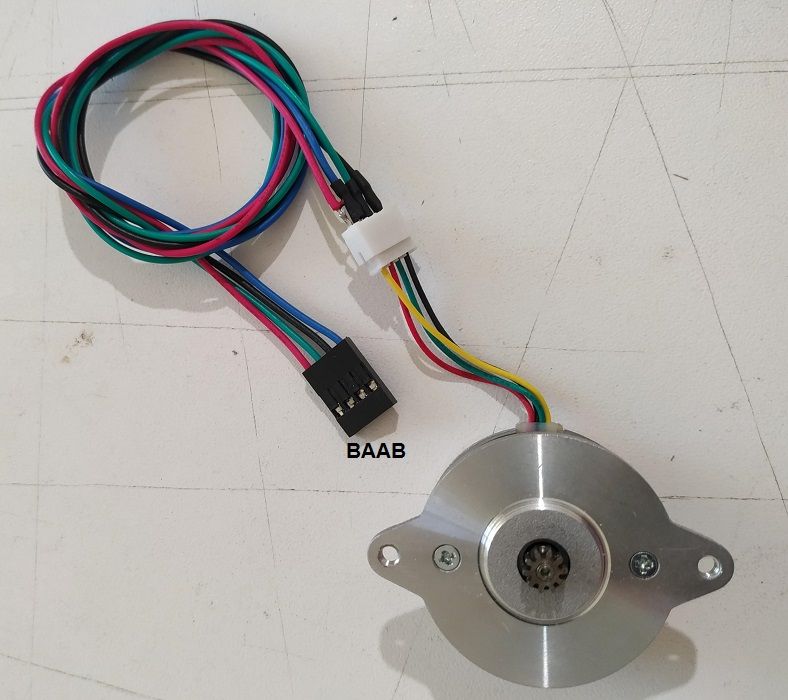
In the "2.) Wiring your Duet 2 WiFi/Ethernet" the foto is BAAB.
But anyway I have tested with BBAA, too, and they act the same. -
RE: Problem with extruder motorposted in Duet Hardware and wiring
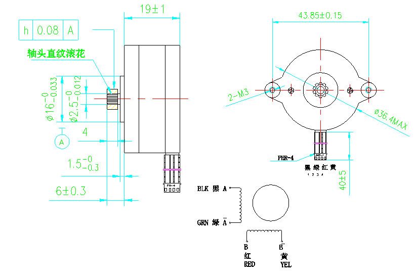
I have checked the motor cables and I verify that they are BAAB as Duet wifi has them.
I still cannot understand why all 4 of them are not turning/ spinning at all, but they act like they are skipping steps.
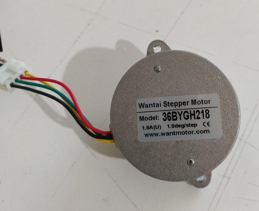
The first two fotos are the motors I have. The 3rd on is from Wantai site, the cable orientation.
Can anyone please tell me, what is wrong and they are not working properly?


-
RE: Problem with extruder motorposted in Duet Hardware and wiring
@fcwilt I have used a multimeter for checking that I am using both A or both B to match with the board A and B. I do not know if the A+ of the board is the A+ of the motor though.
I have plenty of motors and it is the first time to have such a difficulty with a motor. And not just one. I have checked all 4 of them. I am building a toolchanger. -
RE: Problem with extruder motorposted in Duet Hardware and wiring
@Veti I have swapped the wires but it is not working either way.
-
Problem with extruder motorposted in Duet Hardware and wiring
I need some help. I have just instaled the new extruder, "The orbiter", for minimizing the weight. Unfortunately I am having problems with the motor.
I have bought 4 motors from Wantai (36BYGH218, 1.8A, 1.8deg/step)and tested them all, so I do not think it is the motor's problem, because they are all doing the same noise; like ggrrrrr, loosing steps. Nor the board has problem because for ease of practicing I have tried driver3 and driver0.
I have checked the wiring twice. The connections are B, A, A, B on the duet, the same for my motor. I have also tried swapping the cables but is not working either.I have put the configuraton for the extruder as per instructions:
Firmware configurations:
Stepps: 655 stepps / mm @ 16 micro-stepping (for the 7.5:1 gearing ratio)
Acceleration: 600 mm/s^2
Maximum instantaneous speed change (jerk): 300 mm/min(RRF), 5 (Marlin)
Maximum speed: 3600 mm/min
Pressure advance: 0.03s
Retraction: 1.2mm (for the volcano V6 hotend)
Retraction speed: 60mm/s
Motor current:
0.9A Peak or 0.63 RMS(Wantai 36BYGH218)I have tried different currents 1400mA, 1000mA, 900mA and 700mA but still doing the same.
Any thoughts?Part of my config:
; Drives
M569 P0 S1 ; physical drive 0 goes forwards (X axis)
M569 P1 S1 ; physical drive 1 goes forwards (Y axis)
M569 P2 S0 ; physical drive 2 goes backwards (Z axis)
M569 P3 S1 ; physical drive 3 goes forwards (E0)
M569 P4 S0 ; physical drive 4 goes backwards (Coupler)
M584 X0 Y1 Z2 E3 C4 ; set drive mapping
M350 C8 I0 ; configure microstepping without interpolation
M350 X16 Y16 Z16 E16 I1 ; configure microstepping with interpolation
M92 X100.00 Y100.00 Z400.00 E655.00 C100.00 ; set steps per mm
M566 X400.00 Y400.00 Z10.00 E300.00 C2.00 ; set maximum instantaneous speed changes (mm/min)
M203 X16500.00 Y16500.00 Z1000.00 E3600.00 C5000 ; set maximum speeds (mm/min)
M201 X4000.00 Y4000.00 Z400.00 E600.00 C400.00 ; set accelerations (mm/s^2)
M906 X1200 Y1200 Z1000 E900 C400 I30 ; set motor currents (mA) and motor idle factor in per cent
M84 S120 ; Set idle timeout -
Help connecting Duet wifi PS-ON and power supplyposted in Duet Hardware and wiring
Hello,
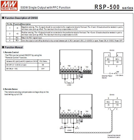
I need some help with connecting the Duet wifi PS-ON and a meanwell RSP500-24 power supply.
This power supply have a remote sense and a remote control function.
I have wired the remote sense as per meanwell instructions, not very hard to do.
My problem is how do I connect the remote control with Duet's PS-ON.
I have included part of the manual that speaks about the remote wiring.
I am not very good with electronic schematics.
The RC+ and RC- (2 cables) which control the remote control I suppose must connect somehow to the PS-ON (1 cable). Meanwell manual reffers to an external power supply, but I do not understand the wiring.
How do I do that?