@eddygara said in My Scalable Delta:
Where can I find the info to this build diagram and parts lsit??
Hi @eddygara ! You can find all the resources here.
Let me know if you end up building it!
Colin
@eddygara said in My Scalable Delta:
Where can I find the info to this build diagram and parts lsit??
Hi @eddygara ! You can find all the resources here.
Let me know if you end up building it!
Colin
@dc42 Thanks! I got a few ordered today.
Hi all,
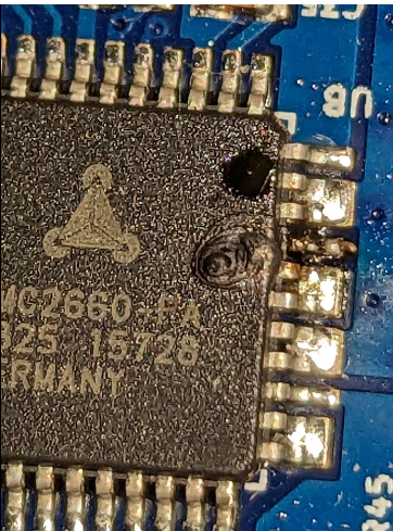
I managed to blow my E0 stepper chip today by miswiring a new motor. It's done a pretty good job of blowing the chip out.
I had a quick look around and the only ones which seem to be available are the TMC2660C-PA in a 44PQFP package - would these do the job? Looking at the data sheet, the only difference from the original TMC2660-PA seem to be some added low side short protection and quieter motor driving.
The part I'm looking at is 1460-1059-ND on Digi-key UK. Can anybody please comment if this would work with a Duet Wifi?
Thanks!
Colin
@droftarts said in My Scalable Delta - release:
@slimshader Lovely looking documentation!
Ian
Thanks Ian - took me ages, but hopefully it will be good enough to help somebody out!
Hi all,
I have finalised all of the design elements including parts, BOM and assembly instructions for the Scalable Delta - I intend to release it on the usual repositories over the next day or so, including Github, but for now it can all be found here.
Please do let me know if you decide to build one - I'd love to hear your feedback!
I intend the design to be completely open source but haven't yet sorted the OSH license yet as I'm not very familiar with how it works or if its even applicable for this. I will state here though, that you are free to use, modify etc any or all elements of the assembly specifics that I have designed including for any potential commercial use. All I ask in return is a name credit and links back to the original files.
Finally, I will also be releasing kits, likely two styles - one with printed parts only and another which would be a complete BOM for the two standard sizes I used as examples. Again, let me know if this is of interest to you!
Colin
@mfs12 OK understood!
For the rest of my interpretation of how to actually use the plugin - does my description make sense?
Looking forward to updates when they come!
@dken21 I just uploaded both the top and bottom vertices.
@dken21 Sure! Not a problem, I intend to share all designs publicly anyway - for now I'm compiling the correct versions so it's all in draft via this link (different from above) and once it's all complete I'll put it on the usual repositories.
Yeah that is a cork sheet between the glass and bed plate - getting a perfectly flat aluminium plate of that scale when it's going to warp on heat/cooling cycles is something of a nightmare, and my top surfaces were being unevenly heated as a result - I found a 1mm cork spacer/buffer made it a whole lot more even during heating and also protects the glass from me not tightening the bed plate bolts down enough.
Mostly I only use the cork spacer in the middle, and over the three bolt holes of the bed on the smaller of my two Deltas, when using Schott Robax Glass as the build surface. If I'm using a flex sheet I cover the entire bed with a larger cork disk.
The larger machine predominantly only uses a Robax glass bed, and I haven't needed to add cork.
I'm always lurking around here and am happy to share my experiences with you - feel free to ping me here anytime!
@mfs12 yes what you are saying makes sense, and I do see an overall reduction in all axis ringing when implementing as I described. However the test is only checking one configured axis, and to me this means that the input shaping is only working correctly for motion along the axis I specified, not in the other two directions. I'm happy to be proven wrong though!
I would expect to either be able to add tests for each axis at the same time in the plugin and evaluate the overall result, or be able to use additional parameters on the input shaping command to specify the frequency for each axis.
@dken21 Thanks! Its nice to know others are looking to build larger format machines too, and I'm not just mad!
My design would accommodate your proposed dimensions, although it would need to be slightly taller than my 2m version in order to achieve your 700mm build plate and still hit the 1m build height, due to the arms needing to be longer.
Printed corners have worked out well for me, each bottom corner uses almost 1kg of PETG and has 3 shells (around 3mm thick in total) printed at 0.6mm layers with a 40% rectilinear infill - in other words, extremely strong. The top corners follow the same infill/shells, and come in at roughly half the weight - again, very strong. Combined with 4040 extrusion it makes for a very rigid platform.
As you will note from the post, I have created two machines, one is 1120mm high, the other 2000mm. I found when testing that on the larger of the two, that bracing it to the wall was a good idea for a couple of reasons - firstly it adds an enormous amount of rigidity to the frame - my particular implementation actually uses 500mm extrusions bolted to 1500mm extrusions to achieve the 2000mm height - because at the time the stockist I was using couldn't source any 2000mm 4040 stock! These joints, although mechanically stable, aren't as good as a solid length.
Finally, the primary reason for bracing the machine was safety - I have a curious six year old who likes to climb on stuff and I didn't want the entire assembly coming down on her if I turned my back for 10 seconds....
Another side effect of adding wall braces was that it made the entire machine quieter on high speed moves - I suspect it's dampening a resonance.
For the other (1120mm) machine, bracing wasn't required at all - it is a very rigid machine free standing. I suspect that machines greater than 1500mm in overall height will require bracing though.
You can get STL and design files for my brackets here - they are functional, but not especially pretty! I suggest printing them with the settings I mentioned above in PETG. If you decide to use them, I designed them with being screwed onto strips of 2 by 4 in mind - additionally, depending on your effector design, you may find that the machine needs to be placed further from the wall than you first think in order to stop the effector fans etc hitting the wall when moving to the bed extremes. For that reason, there is also a printable 'spacer' included in the design file.
On the motor side, currently I'm using Nema17s all round - 0.9 deg on the smaller machine, 1.8 deg on the larger machine - mainly so I could compare the two systems practically. I'm toying with putting Nema23s on one of them, but to be honest unless the tool weight increases a lot I don't really see the point.
Re: InputShaping-Plugin-0.2.0-pre8 released
Hi @mfs12! I just wanted to give some initial feedback on the plugin, based on my playing around with it for a week or so.
Firstly, wow...you're definitely on the right track here with functionality. It's awesome to be able to try out different algorithms and settings in a batch format and be able to compare the results - fascinating stuff!
In terms of usage, some more explanation of what we are looking at, suggestions on logical starting points and how to interpret & implement the results and recommendations would be great for people like myself who are not very familiar with the process would be fantastic. Whilst I appreciate that this is all pre-release/under development etc, in order to be able to give proper feedback I need at least a cheat sheet on usage and how to measure success. Saying that though, I'm personally equally happy just playing around to see what happens - I'd just like to do that a bit more efficiently!
So I'd like some feedback on my current process for using the plugin - I suspect I'm making some mistakes or most likely missing tricks.
I pretty much follow the release notes 'howto' section:
Create a new session, and select it
Move to Configure and select axis, start/stop motion constraints
Add all available types of input shaping, using defaults
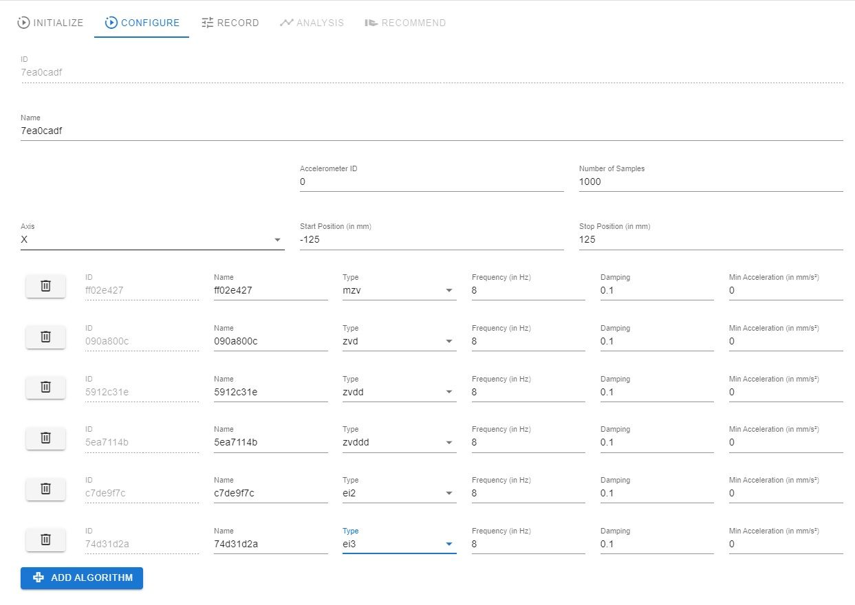
Question - I can see that Frequency/Damping/Min' Accel' can be configured - how do I ascertain which values to use if not the defaults? My assumption is that you run a baseline measure measurement with no input shaping, and change the values based on observed vibrations?
Move to record and hit run
Switch to Frequency analysis and try to look like I know what I'm talking about until the wife leaves the room.
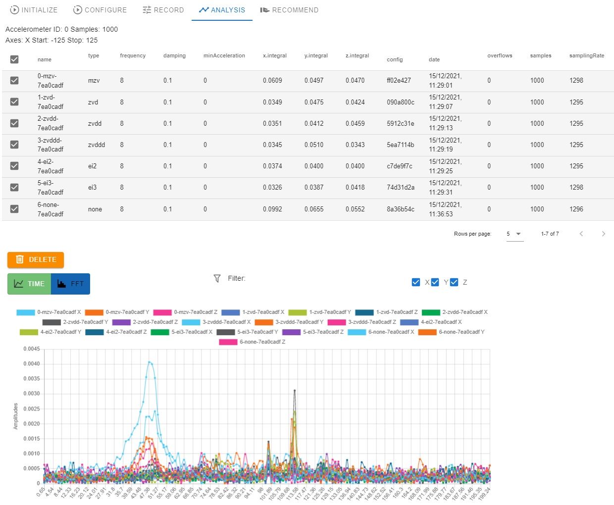
Move to Recommend, and select the 'none' record with no shaping and hit Run Recommendation
Question - The resulting table gives me a bunch of results which I can kind of make sense of. I know I'm supposed to sort by integral, and look at the smaller ones - so far so good. Why is the recommended frequency changed to 11.02hz though? I thought the biggest low end spikes were observed between 38 and 53hz???
Anyway, at this point I start to get very confused. I can swap between the different recommended records and see on the FFT which ones look like they have the lowest amount of vibration recorded.
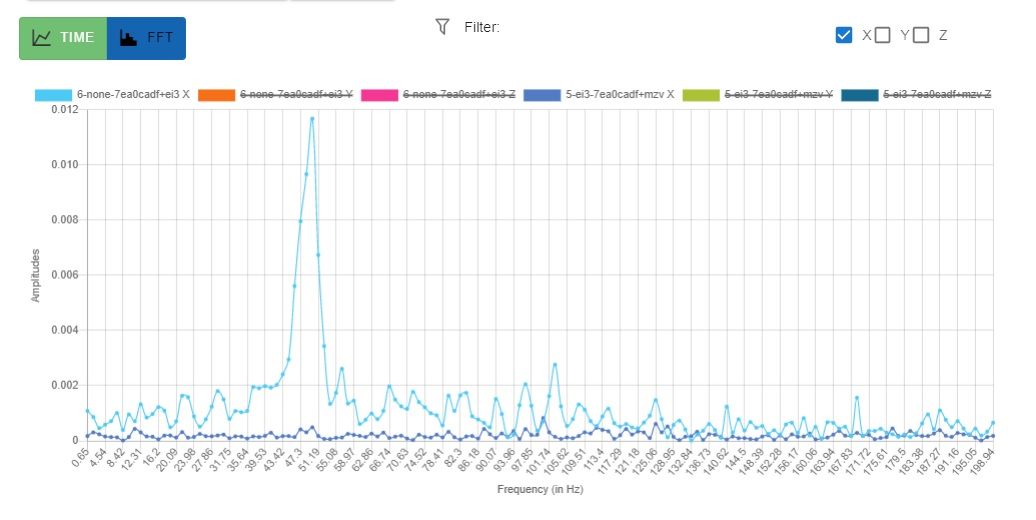
Looking at this, I can see that record 5-ei3-7ea0cadf+mzv X is giving great results.

So how do I implement that? Looking at the record, its recommending 11.03hz in this instance, so I use M593 P"mzv" F11.03 in the console.
Now this I think makes sense - however it's just the X axis calibration right? Should I now be taking further measurements of Y/Z and somehow combining the results?
Incidentally, by using the MZV shaper as described above, I did see a good improvement in print quality, reducing X axis ringing significantly. However, it's still showing on the Y axis at the same degree as without any shaping at all.
Overall, I'm really happy so far - this is interesting and has a positive impact on print quality - but obviously there is still a ways to go.
I'm happy to continue feeding back and asking dumb questions if it helps with the development too!
Colin
@janjoh yeah I will be, although I only got my order in yesterday and the delivery estimate is early January. I'll share whatever I create on here and in the usual repositories.
@t3p3tony Thanks Tony - I see that the plugin requires 3.4.0b6 - I'm happy to install that but I would like to request the process to upgrade from 3.3 to beta releases?
Do I just download all the assets to the system folder and restart or is there some other process required?
HI all,
I have got a LIS3DH accelerometer attached to one of my Delta Smart effectors (thanks for the pin wiring advice @dc42 !) and am attempting to understand the next steps.
Currently I'm running the RRF 3.3 so the only shaping option I have available is DAA. I can see in 3.4 and above there are further input shaping options available, however these are not stable releases as yet, so I'm not sure how to update to a beta version - can somebody point me to the process to install beta firmware from 3.3 please?
Next, is how to interpret the accelerometer results. The FFT below shows my results using the command G1 X-150 G4 S2 M956 P0 S1000 A0 G4 P10 G1 X150 F20000.
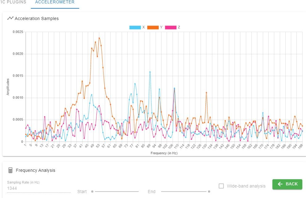
Looking at the graph, it seems most of the low end ringing is between 38Hz and 58Hz, which I would expect based on what I've read.
So here's my questions:
I'm assuming if I run another M593 command it will simply overwrite the previous one, so I don't see how to fine tune for each axis.
Is there a best practice for which measurement point one should start damping from?
In the Accelerometer plugin, the default frequency sample rate seems to change per reading taken, and is usually between 1292 - 1296, whereas the output of the accelerometer is 1344 as per the instructions - should I be changing the value to 1344 before hitting the "Analyse" button?
Looking forward to your advice - this is a very interesting exercise!
Colin
Absolutely saddened by this news, Sanjay was an inspiration and evangelist for the community. He will be greatly missed. My condolences to his family and friends.
@dc42 Thanks David, worked first time 
@achrn very observant sir! Yes, I'm UK based.
I got my Robax plates from an eBay seller here called Firebranchdesign.
I highly recommend them - excellent fast service, custom shapes and sizes and very quick delivery. The plates come well packaged and in perfect condition - they are extremely durable too.