Hollow shaft extruder
-
Biggest issue is the hot hollow shaft, not an easy task to solve.
-
@tecno Will it be hotter than the following heatsink?
Which filament will suffer the most?- ABS will even like it to be preheated
- PETG, I don't know
- PLA, perhaps above 60°C?
Maybe we find a 3mm OD PTFE tube that fits inside the shaft? Or cover the inner shaft wall with Kapton tape...
One step at a time -
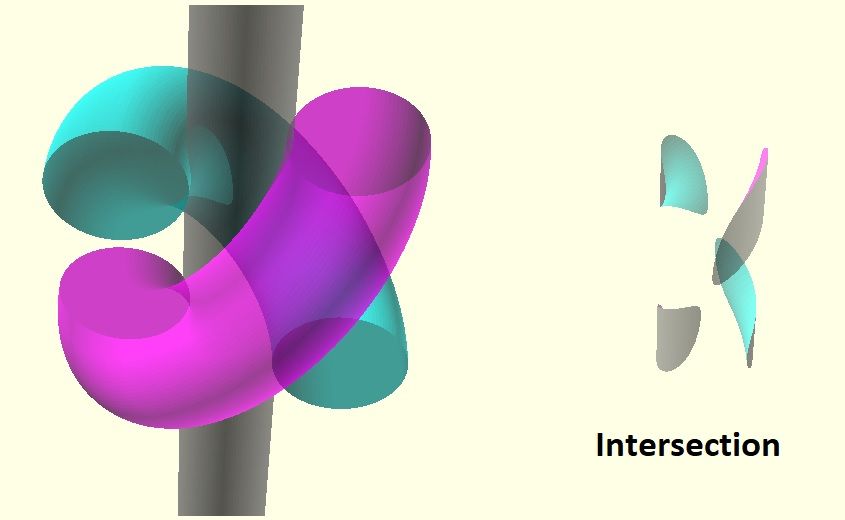
In the meantime, I sketched ballraces wrapped around filament. (I have a bag of 2.3mm balls for mgn12 maintenance)
The races should intersect with the filament at the angled part, but not at the start/endpointThe intersection I achieved looks a bit odd, but i can't figure out how to solve it in openScad.
-
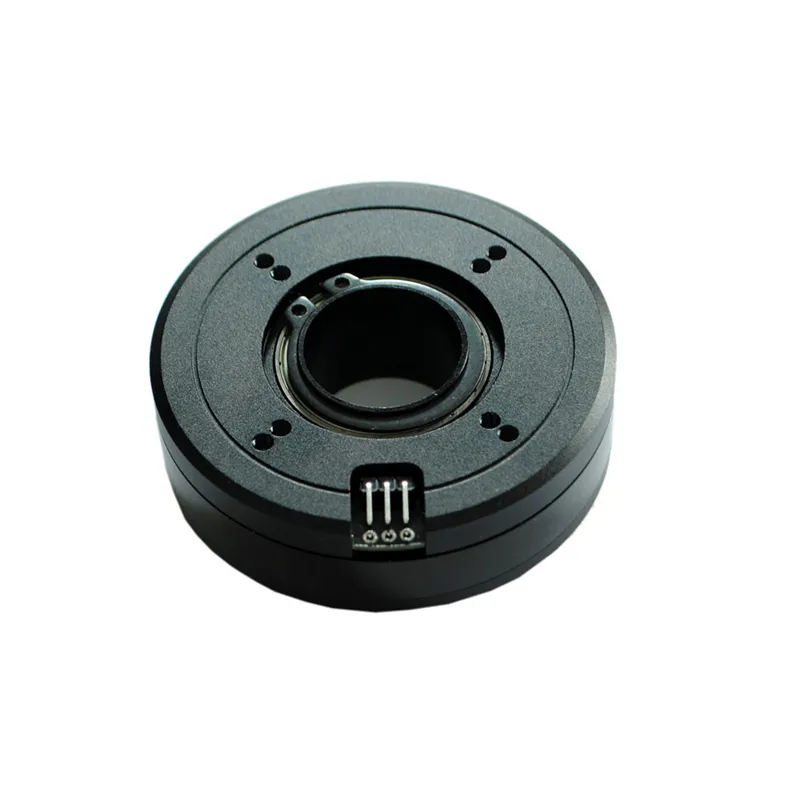
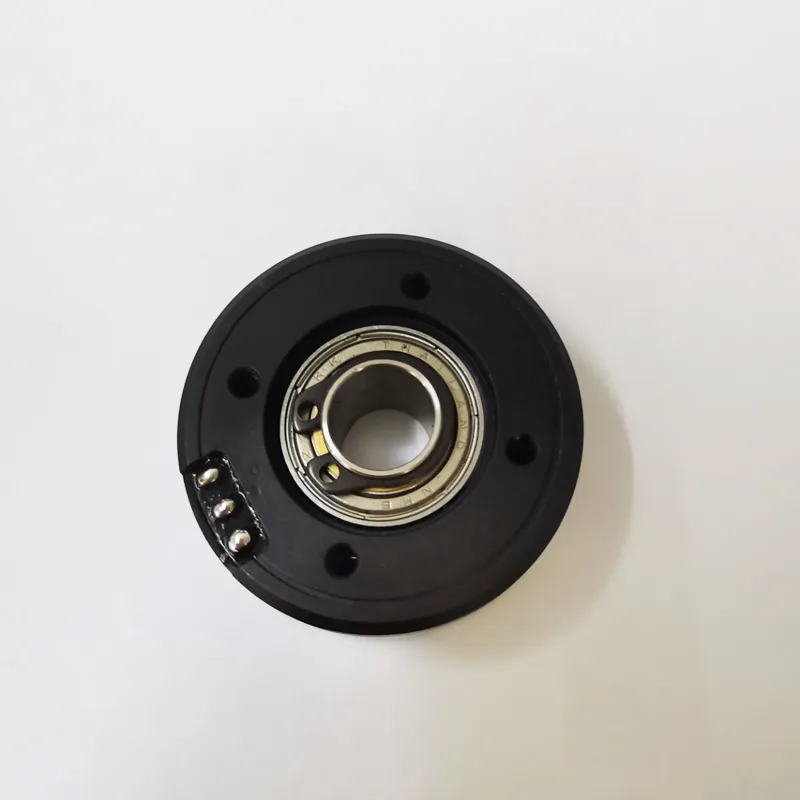
@o_lampe Check this one.. opensource design with files on github.. Uses a BLDC motor + encoder.
Weight is just below 90g.
Demo of it in use.
https://www.youtube.com/watch?v=f0SuaIMxAs0Assembly video
https://www.youtube.com/watch?v=wmcOtlD_yG0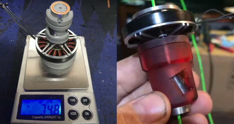
-
@tecno It's not a problem if the motor does not get hot and that's ultimately a function of gearing ratio. I have been using a hollow shaft for over a year with no problems at all.
-
@pakar I like that approach with the stepper below the screw part. That would be a good idea on a Smart-Effector, too. If only there weren't so many connectors...
A pancake is so short, the filament won't have much time to heat up. -
@JoergS5 said in Hollow shaft extruder:
would it be possible to prepare the filament (eg near the filament holder) with grooves in advance, so the requirements are lower for the extruder (only Z movement needs to be exact), or is this patent protected? (I cannot remember the printer name, with special filament gear rod at one side)
Lining up the groove with the wheels would be tricky. What is most likely to happen is you cut another thread and the excess cutting grinds the filament into dust.
And, responding to the question about patents, there is a potential problem here. Fuselabs has a patent which covers the VDE-100 and any variation you can imagine. However for VDE-100 specifically, and perhaps other variations, there is prior art. See https://www.patreon.com/posts/threadless-or-57786089.
-
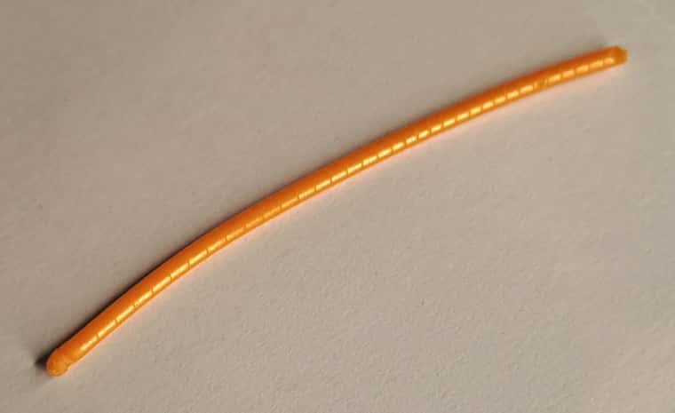
@nikscha Here are some filament photos for you. This piece of filament was fed at a constant 6mm/s. Initially there was no load as it moved through the heatsink. When it hit the nozzle, the load increased rapidly and the thread pitch became compressed.
Here is a close-up showing the shape of the groove in profile. As you can just see when the pitch compresses a slight ridge develops parallel to the groove and the groove widens.
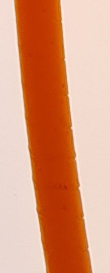
It's pretty difficult to photograph this, so apologies for the imperfect images.
-
Does the "thread" compression occur because the bearings used to cut them wobble a bit? If you used two wheels to cut threads on each of the 3 positions, and mounted the cutters on a short rod or tube with a bearing at each end, the wobble would go away and so might the thread compression. Or maybe needle bearings would be better than ball bearings for this application.
You can get 5mm dia stainless steel tubing via amazon: https://www.amazon.com/uxcell-Stainless-Thickness-Seamless-Straight/dp/B082FGC8XG
If you can't drill the motor shaft, I suspect you can press the shaft out of a motor and replace it with a tube without too much difficulty. I think the hot hollow shaft is only a problem if you print with PLA. I can't foresee the future and can't say for sure that my prints will never end up in a hot car for a few minutes, so I prevent problems by not printing with PLA.Slightly off-topic, we went from mostly using 3mm filament to 1.75mm because the extruders could be made smaller and the smaller diameter filament can melt faster. Why aren't we moving to 1mm filament? The reduced diameter would allow melting the filament almost right at the nozzle and a lot of extrusion problems would go away, I think.
-
@mrehorstdmd Re: smaller filament
I made my own 0.8mm filament a while back. 0.8mm because 1mm ID PTFE tube was available. It would help shrinking extruders and reduce weight.
I couldn't test much, because there was no hobbed gear that I could use.
The screw extruder would also be difficult to adapt; needs much smaller bearings and so little filament to bite.
@deckingman Do you think, mixing extruders would benefit from thinner filament diameter? Toothpaste-effect a.s.o...Talking about making filament: It would be nice to have threaded filament right from the roll.
The intake of the extruder would have a matching thread and it rotates with the bearings. So the thread would align automatically . -
This post is deleted! -
@mrehorstdmd said in Hollow shaft extruder:
Does the "thread" compression occur because the bearings used to cut them wobble a bit? If you used two wheels to cut threads on each of the 3 positions, and mounted the cutters on a short rod or tube with a bearing at each end, the wobble would go away and so might the thread compression. Or maybe needle bearings would be better than ball bearings for this application.
I don't think so. It happens with ABEC-5 bearings which have very little play. My best explanation from examining the filament is that the compression is caused by distortion of the plastic.
-
Has anyone tried a knurled roller rather than a set of "blades"?
Polar Duet3 Mini + 1HCL
https://youtube.com/playlist?list=PLWjZVEdMv1BY82izahK45qKh-hp3NFkix
Wanhao D4S: Duet2
https://forum.duet3d.com/post/296755
K40 Laser, Duet2
https://forum.duet3d.com/post/312082
Wanhao D5S
https://www.youtube.com/CNCModellerUK -
@tombrazier I don't like to load a ball bearing right at the edge (flange), That's why I proposed the roller with the cutting edge in the middle.
It would also help, if you'd add a supporting disk on top of the bearings to prevent them from getting spread apart. -
@CNCModeller So far I've read about aluminum-oxide powder coated or sandblasted rollers, metric screws without any ball bearing, flanged bearings and the guy with the brushless motor uses DIY rollers with a fine pitch rounded thread.
A knurled roller (with a criss-cross pattern?) wouldn't cut a thread in the filament. That's similar to the failed sandpaper-rollers, I guess. -
-
@o_lampe said in Hollow shaft extruder:
So far I've read about aluminum-oxide powder coated or sandblasted rollers, metric screws without any ball bearing, flanged bearings and the guy with the brushless motor uses DIY rollers with a fine pitch rounded thread.
A knurled roller (with a criss-cross pattern?) wouldn't cut a thread in the filament. That's similar to the failed sandpaper-rollers, I guess.That's pretty much what I think has been tried so far as well. With the contact area on the 1.75mm filament being quite small due to the radius of curvature of the filament, I suspect any knurling that might work would have to be very fine. I did try roughening the surface of the bearings with sandpaper and that produced far too little friction to be of use.
The threaded rod, by the way, is equivalent to putting the bearings at a cant angle.One or other can be used or, as with the BLDC one, some combination.
I don't like to load a ball bearing right at the edge (flange), That's why I proposed the roller with the cutting edge in the middle.
Hmm, I had not thought of that. I wonder whether there is or isn't any effect at play here.
I found this guy who forked the project. He uses a smaller brushless motor and added a quick-release system for filament change. Last commit was one year ago, but still a work in progress.
A reliable quick release would be cool for the VDE-100.
-
@o_lampe it was mainly to spark some ideas.
A possibility with this type of design could be to flip it around with the BLDC on top and then use a larger bore where you get some insulating air around the filament. A open style BLDC would also have more surface area to dissipate heat compared with a enclosed stepper.
Quick look gave me these two:
https://www.aliexpress.com/i/4001147807182.html
Outer diameter : 68mm
Bore : 22mm
https://www.aliexpress.com/i/33008455482.html
Outer diameter : 40mm
Bore : 10mm
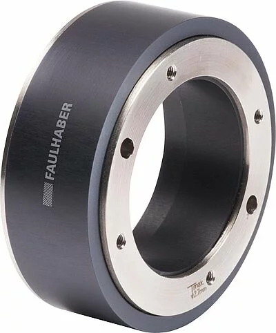
With a planetary reduction gearbox might be possible to use a higher rpm motor (more volts & RPM but lower amps), but not too good myself at calculating forces for those things and how much weight that would add. (igus plastic gears?)If sticking with steppers there are some larger-bore steppers out there too. Found this one but without pricing.
https://www.faulhaber.com/en/products/series/dm66200h/
-
@pakar I don't think, the center hole would need to be bigger than 4mm. Then we can fit a common 4x2 PTFE tube as insulation. Same as with most hotends I know.
I'm not against BLDC motors, they run super smooth and very silent. But we'd need a better interface-board than the O-Drive Arduino-shield@dc42 would it be possible to integrate BLDC support on a small Duet3 board? With a 3x H-bridge as driver, it could be a simple RP2040, I guess.( with the encoder on a state-machine)
-
I thought of another way to support the rollers and my other hobby came handy:
Saxophon repair kits come with these screws.
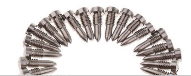
The rollers would have center holes matching the shape of the screw tip. Voilá, low friction and precise guidance.