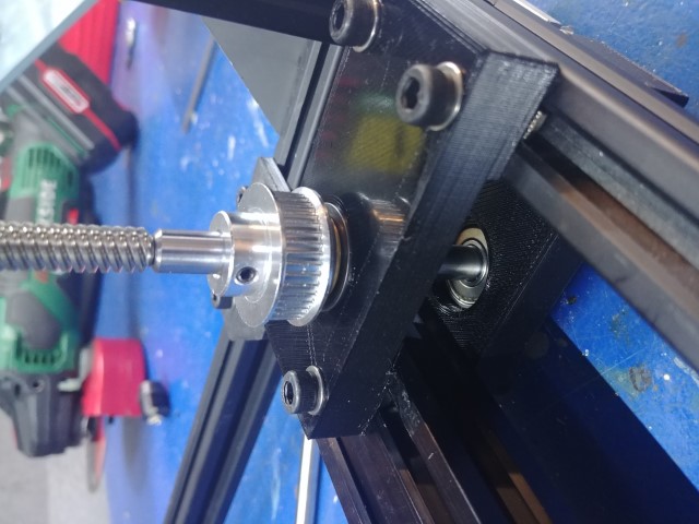
Best lead screw - ball bearing mount system
-
@deckingman I had the exact same thing happen!!
-
Thank you for all your suggestions.
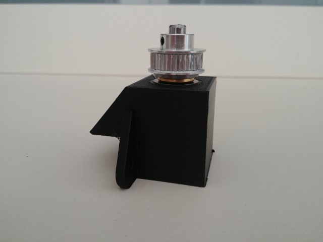
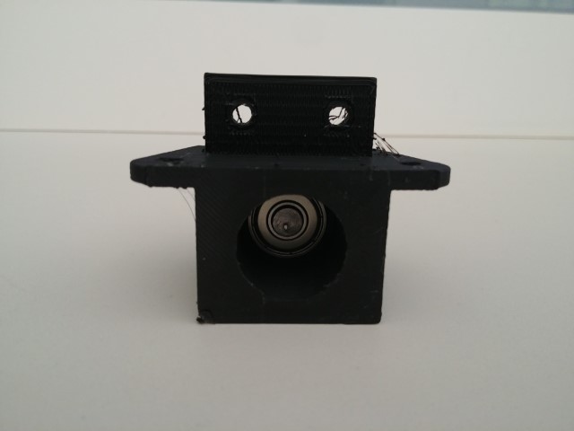
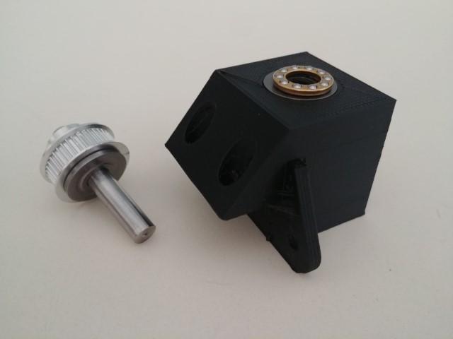
This is what come out .
I moved the thrust bearing on the top so it can discharge the weight of the bed on the plastic structure.
Below I installed the ball bearing that doesn't have to manage weight.
I am still waiting for the rigid coupler.what do you think
?
-
Looks good to me.
-
That'll do.
-
With this sort of thing I tend to think about what might go wrong and what I can do to prevent it. I try to only have to do things once. Making things as close to ideal (in the relevant properties) as possible reduces the things you have to consider if something goes wrong. If I use a plastic part in an assembly I tend to make it bulky to ensure rigidity, so I wouldn't use thin plastic flanges, even with side-webbing, to support a relatively large weight or something that will be loaded by a drive belt.
At the very least I would thicken the flange that bolts to the top side of the t-slot, maybe to the point of making it continuous with the body of the part. I'm not saying that your flange design won't be adequate, but if it isn't, you'll be redesigning and reprinting.
In the end, you should worry less about the plastic flexing and more about the t-slot it's bolted to twisting.
-
@mrehorstdmd
is something like this enough "bulky"?
-
Yes, I'd do something like that. I'd also use modifier meshes to increase the fill density around the mounting bolt holes.
-
that reminds me there was a video by alex kenis about this
https://www.youtube.com/watch?v=2Z7mZVvPlc8 -
While I am trying to fix the squareness of the frame I finalized!the Z axis belt system
This is what it came out.
I tried to make the belt running as much as possible around the pulley with this setup all the pulley has 180 degree belt contact.
The 2 tensioners are temporary , I am going to print a support for it
Any suggestion will be appreciated.
Thank you
Andrea

-
@claustro How come those front two lead screws are set so far back from the front of the frame?
-
@deckingman this is only a temporary disposition , at the end the 2 front lead screw will be as far as possible from the back one
-
@claustro said in Best lead screw - ball bearing mount system:
@deckingman this is only a temporary disposition , at the end the 2 front lead screw will be as far as possible from the back one
Ah OK. I was a bit concerned that the two side rails might flex due to the weight of the bed acting so far away from the end fixings. Those "Tee plates" might flex though. If you can, check for any deflection by using a dial gauge if you can lay your hands on one, and adding a weight to simulate the weight of the bed to the top of the lead screw couplings.
-
I am trying to use your Z rail configuration with only 2 carriage in a diagonal disposition .
If you talking about the plastic tee plate , the one that fix the 2020 that support the 2 front lead screws, I am going to switch to aluminum one as soon I 'll have my CNC running . ( it will be my first easy test with aluminum )
)I have a dial gauge and I surely check what you suggest.

-
@claustro For info, here is how I mounted my lead screw blocks.
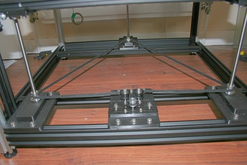
So each block is supported on two 2020 extrusions. One might be OK but check for deflection.
-
I have 2 spare 2040 peaces I can always copy your design in case I'll find some flex
-
I changed the setup following your tips this is the result.
Now I have to choose if make a bed leveled by lead screws or by another set of screws only for the bed.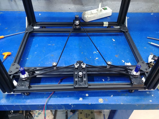
-
@claustro That looks very familiar

-
@deckingman eh eh

-
I am thinking to change my setup.
with only one bearing when I tension the belt the shaft tend to be dragged towards the centre, creating tension on the lead screw, for this reason I am making another support for another ball bearing under the previous one fixed on the other side of the vslot. The 4cm distance between the 2 bearing should improve the stiffness of the system. -
this is what I did
