New heated enclosure printer
-
@phaedrux Here it is! New restock on dhm-online.com
Come and find your duet 3 new products: duet 3 6xd and more https://www.dhm-online.com/brand/14-duet3d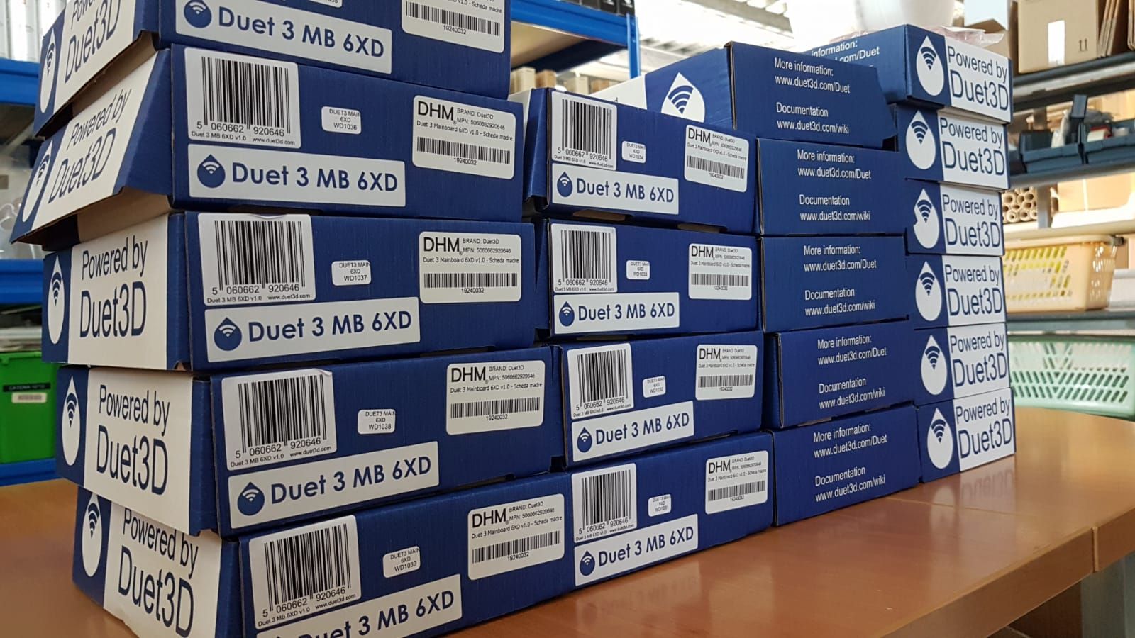
-
Heaven to hell!

After the first round of printing I left the printer off for a couple of months, and now have some revisions to print.
Not sure what happened, but quality has taken a nosedive from previous results. Suspecting the PCD nozzle was an issue, I swapped back to the all copper but the results were the same. The blue parts were from an old spool. After a couple of bad ones, I baked it for a few hours at 65C but that did not improve things. I then tried a new spool of white and got a little better but still far from acceptable parts. I was using the same settings and for the blue parts tried importing the settings from the .gcode file of a previously successfully printed part. I even reran an old file with the same substandard results.

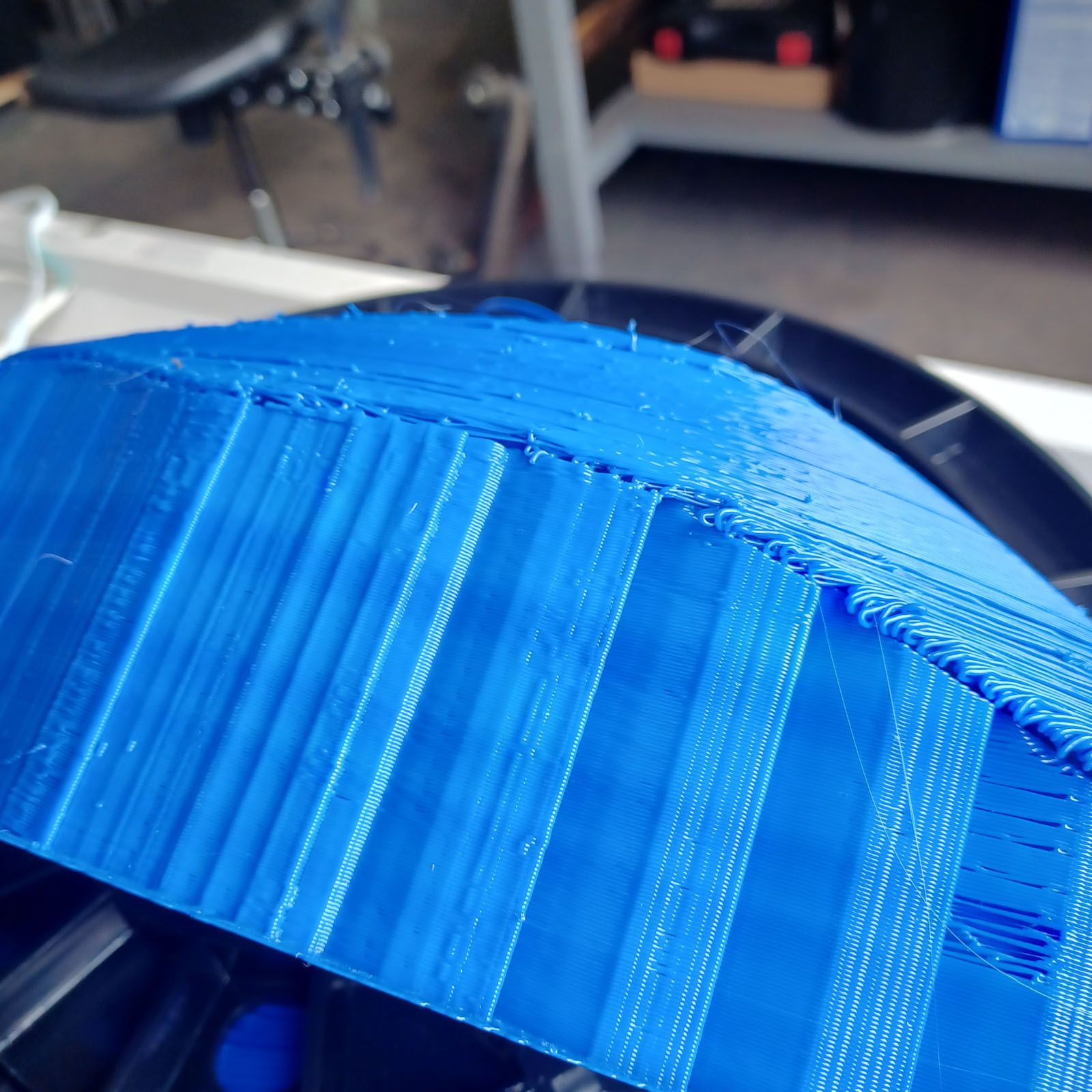
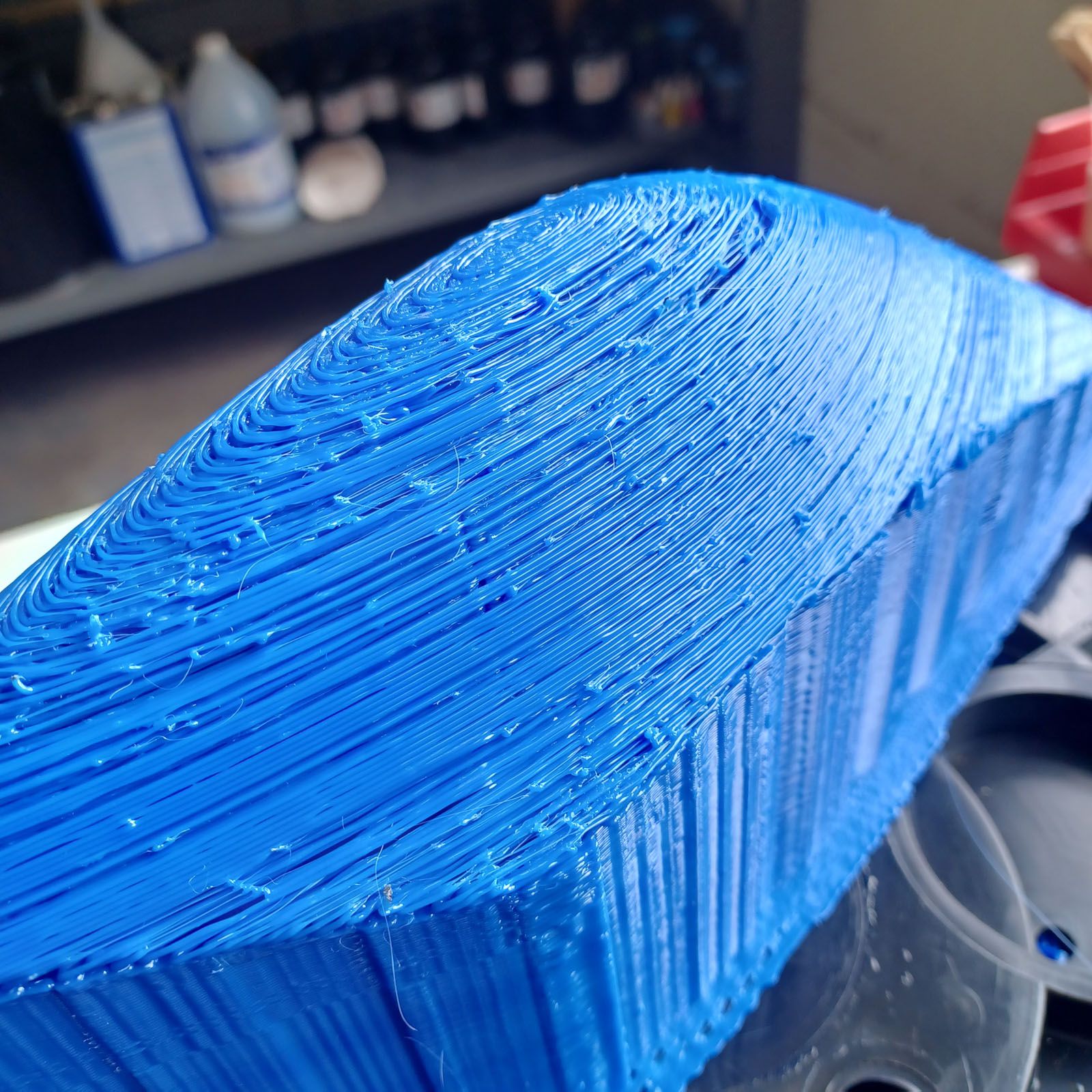
Any ideas on what could be going on? All the mechanicals seem to be tight. At the end of the 22hr white print (or any other print) there was no filament dust or shards at the pinch roller.
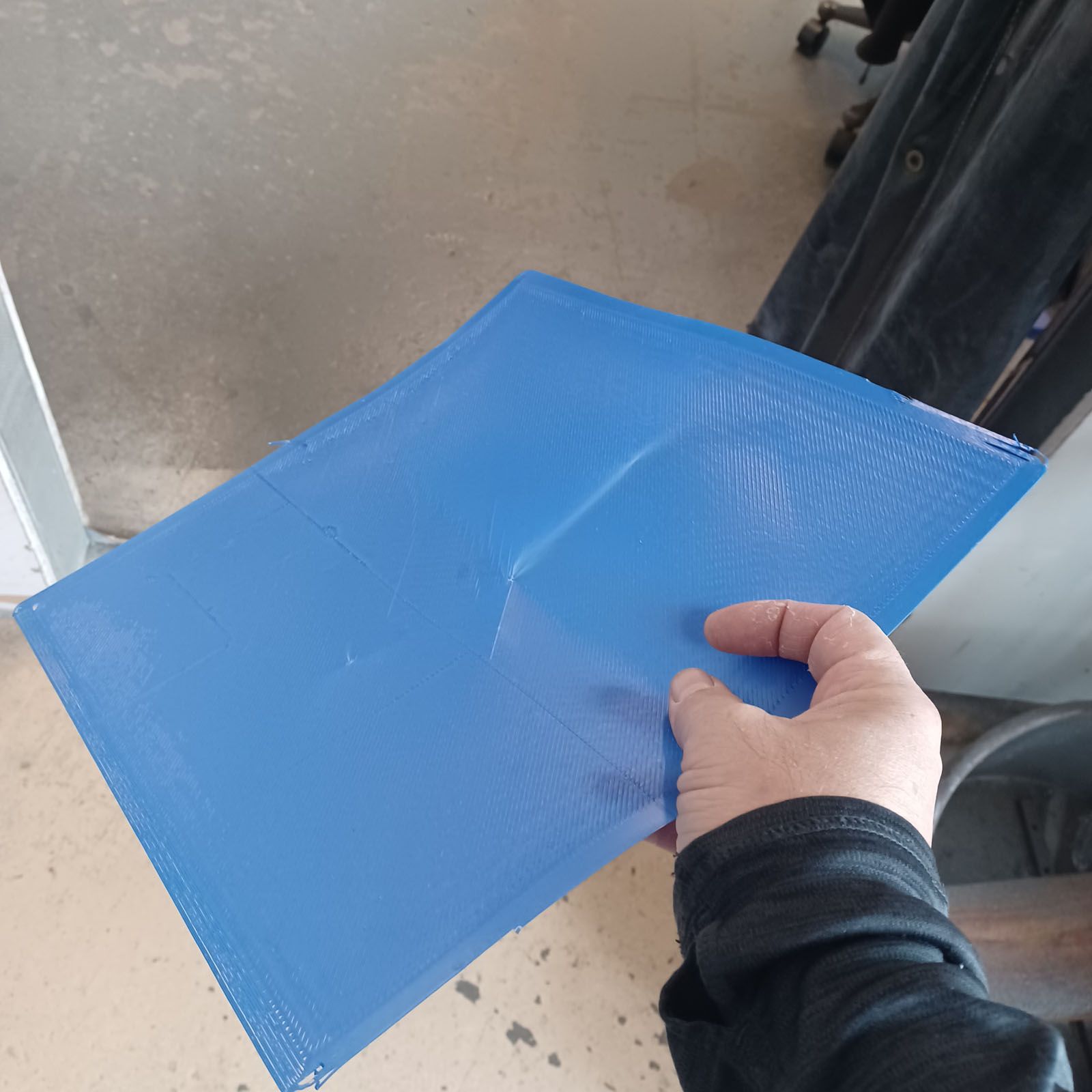
A single layer flat part prints fine.
I'm at a loss and tired of wasting filament.
-
Seems like pretty bad under extrusion.
-
@phaedrux Ugh. I wonder why. Well, have to leave it as-is until next week and have some time to debug it.
-
@Phaedrux said in New heated enclosure printer:
Seems like pretty bad under extrusion.
Yup, modified the extrusion steps/mm on a small print until it came out good. About 20% more. All the other settings remained the same. Not sure how this happened but I guess sloppy setting management is the most likely culprit.


The overall finish is decent, but I feel could be improved. The taller parts suffer from some sway during printhead rapid moves acceleration, which is a bit surprising as the overall printer is pretty heavy. The waviness is pretty minimal in the lower sections and becomes more noticable as you get taller in Z. Maybe I can stick some chunks of steel in the base and see if it reduces sway. I also think my attachment of the very rigid Z axis linear way/leadscrew assembly to the overall chassis could use more stiffness, but am a bit reluctant to dig into mechanicals as the parts are quite useable as-is. Just a good lesson to be learned (again) that in a 'machine tool', stiffness everywhere is important.
Another option could be to reduce the acceleration rate, as lots of these moves are long, so a small increase in acceleration time won't add that much to overall print time. That is a tough route to go, as I'm a racer at heart.
-
And also now that it seems to be stable and printing well, I'll try to get to adding the second printhead soon. Immediately it could be used to embed a colored logo to the parts.
Mirrors and duplicates would be nice for several of the fairing parts. Any recommendations on a slicer that handles CoreXYUV?
Chris
Cosentino Engineering -
@coseng said in New heated enclosure printer:
Any recommendations on a slicer that handles CoreXYUV?
I think most will as is. What do you use now?
-
@coseng said in New heated enclosure printer:
Mirrors and duplicates would be nice for several of the fairing parts. Any recommendations on a slicer that handles CoreXYUV?
That depends on what you want to do. CoreXYUV will allow you to home XYU and V indepently but slicers don't generate UV moves, only XY. So there are two options, both of which I use. Firstly, and by far the simplest, is to map the U and V motors to the X and Y axes. Effectively making the machine one which has two Alpha motors and two Beta motors serving the XY gantry. The second method is to write as script to post process the slicer gcode file to add the U and V moves to the end of the G1 Xn Yn En moves and don't combine the axes after homing. I use the latter more often than not because my UV gantry sits above the XY gantry and carries the 6 extruders. So I don't want this UV gantry to exactly mimic the XY gantry, but rather to follow it within an allowable tolerance. So for example, the extruder gantry will "park" in the centre of a smallish cylindrical feature, while the hot end gantry does the necessary moves to print that feature.
-
@Phaedrux I am using Cura 4.13 now. Maybe it is time to check out the 5.2 as they also have another thin part slicing update to simulate injection molded parts, which is what my parts are (should be) like.
-
@deckingman said in New heated enclosure printer:
That depends on what you want to do.
I'd like the printer to print two copies of the same part at the same time, or print a part and it's mirror copy both at the same time.
Chris
Cosentino Engineering -
I'd still like to tweak the settings to improve some of the print artifacts that are still happening if I knew what to tweak. Particularly on sloping underside surfaces.
This is a test fit part for a friend's vintage supercharged '53 Corvette that will be DMLS in aluminum from prtwd.com. This was a 4 hr print time. It will be a thin wall tube, but is easier to print as an infilled solid for mockup purposes.

I printed 3 of them and they all had consistent problems in the slightly sloping underside area.

To try to improve the finish of the area over the supports I increased the support roof from 1 to 2 layers and the support top looks nicer, but the part underside looks the same.

And there are print problems that are not above the support area.

These seem similar to the initial problems that were occuring back in the middle of the thread with the red and white panel-like parts. Those problems were never resolved, just avoided by changing the geometry. These parts are not thin or panel-like, but the printing quality problem has a similar look.
-
@coseng Try printing in wider lines and thinner layers. Prusa slicer will automatically adjust layer thickness based on overhang angle/detail (I think) if you enable it.
-
@mrehorstdmd said in New heated enclosure printer:
@coseng Try printing in wider lines and thinner layers. Prusa slicer will automatically adjust layer thickness based on overhang angle/detail (I think) if you enable it.
Hmm, so you think the bead is falling off the edge of the part before adhering? I am printing the outer wall last to try to prevent that and this part has 3 walls. It is small enough to test with and I can cut off the lower section to get right to the problem area. Maybe higher print temp too to make the bead 'stickier'?
-
@coseng Not quite ideal, but I've set Cura up such that when a third tool is enabled (and of course selected to print the model with - get the right tool-changes in RRF), the machine disallowed area (preview) represents the printable area of half my build plate.
https://forum.duet3d.com/topic/13696/new-large-format-idex-printer-project/22
https://www.youtube.com/watch?v=z_CbTmiBqswI say not ideal, as the way I structured this approach is 'if the number of active extruders is greater than 2, limit my print area to this width'.
"machine_disallowed_areas": { "value": "[ [ [0, -237.5], [0, 237.5], [225, 237.5], [225, -237.5] ] ] if len(extruderValues('extruder_nr')) > 2 else []"}A better approach, but one I couldn't get to work, would have been 'if extruder 3 is selected, limit my print area to this width'. One of these days I'd like to take a look at the inner workings of the various BCN3D forks of Cura (their old Cura, and their new Stratos) and see how they handle the machine disallowed area. They allow you to select a print mode (like a Cura quality/nozzle selection), which injects the mirror/duplication GCODE into the preamble of the print file.
-
@sebkritikel said in New heated enclosure printer:
Not quite ideal.......
Found this online which says IDEX support so will give it a try:
https://www.bcn3d.com/bcn3d-stratos/
https://support.bcn3d.com/knowledge/bcn3d-stratos-introductionIt is based on Cura so the settings should be familiar, and interestingly enough found a post online relating to native Cura IDEX support:
-
@coseng If you want to go further down the rabbit hole, some other discussions I had on a user in regards to BCN3D's forks (and slicer/IDEX compatibility in general):
https://forum.duet3d.com/topic/19167/creating-a-new-idex-3d-printer-with-duet-2-wifi/31?_=1670003869964 -
@sebkritikel A rabbit hole is exactly what I am trying to avoid!
") Didn't see that Merlin firmware part, maybe they've made progress in the past year or 2?
Didn't see that Merlin firmware part, maybe they've made progress in the past year or 2? -
Hmm, IDEX is not as plug and play as I was hoping!
An alternate solution is to repurpose the extra UV Clearpath motors and build a CNC plasma cutter with them. They are more than strong enough to push a plasma gantry around pretty quickly and from what I can see with some friends that purchased stepper based tables, unless you spend well into the $10ks, the Duet control board seems to be a step up, and the Clearpath motors are two steps up! A 4'x4' CoreXY cutter would be pretty useful and more rigid than most of the table setups I see out there.
@dc42 , I saw some older threads about it but there never seemed to be any final results. Did you end up doing those software modifications you were talking about for the torch height control?
https://forum.duet3d.com/topic/8403/advice-on-adding-plasma-torch-height-control/10
@fall-apart-dave @mawildoer @andymidtf
Did any of you ever make it to a working Duet-based machine? -
With this cold weather we're having my big industrial space is at least 15F colder than it was in spring/summer and the machine is misbehaving a bit. After a bunch of heater errors I had to rerun the heater optimization routines and think the bed 'shape' is a bit off as I am having first layer adhesion problems, but only on the corner of a big part. The first layer extrusion is mostly flat but is roundish where it is not adhering, so think the bed is drooping a bit. My bltouch is fried so I have been manually setting Z, but am not sure about the heightmap file format. I can use a plunge indicator mounted to the carriage to accurately map out the bed, but am not sure how the file entries are mapped to the bed.
For the heightmap file below are the matrix entries, does the first entry of -.094 correspond to (maxX, maxY) or (minX, MinY)? Are rows X and columns Y? Does a negative value mean the print is closer or further from the printhead?
RepRapFirmware height map file v2 generated at 2017-07-21 20:53,
axis0,axis1,min0,max0,min1,max1,radius,spacing0,spacing1,num0,num1
X,Y,-310.00,315.00,-288.00,288.00,-1.00,156.25,288.00,5,3
-0.094, -0.047, -.020, -0.127, -0.18
-0.094, -0.047, -.020, -0.127, -0.18
-0.094, -0.07, -.010, -0.127, -0.18
-0.10, -0.07, 0.000, -0.127, -0.18
-0.10, -0.09, 0.010, -0.127, -0.2Thanks.
-
@coseng each row is a set of X points from min to max. The first row is min Y, the last is max Y.
Duet WiFi hardware designer and firmware engineer
Please do not ask me for Duet support via PM or email, use the forum
http://www.escher3d.com, https://miscsolutions.wordpress.com