Issues with pressure advance since RRF 3.4
-
@argo why do you point at the infill intersection break as evidence for PA tuning? There is no PA action at that point, since those are uninterrupted straight lines, which cross.
More important would be at changes in direction, but it would be much more helpful if you labeled the direction of travel for each infill line you are considering, since without it you can't guess.
-
Because it’s a very good indicator to rate infill quality. At the end PA is a compromise between infill and perimeter quality.
One last example with input shaper enabled to show how much it decreases quality further:
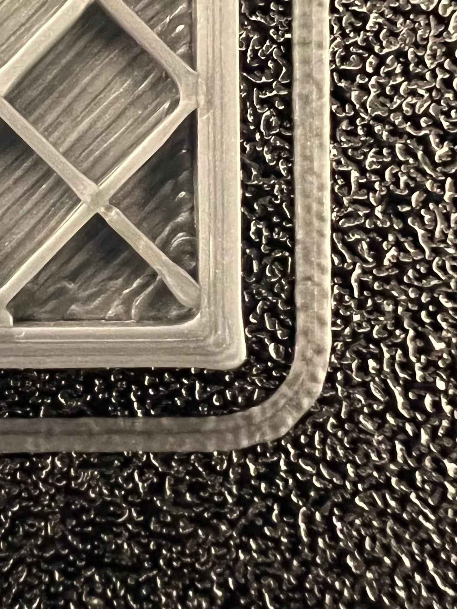
For me the test and demonstration journey ends here. I could wire the extruder Motor directly to the board though so it does not run over CAN but I feel tired testing and experimenting for now.
Until I enjoy experimenting again there is hopefully something that might be a fix or I’ll switch over to Klipper. -
That looks a lot better.
Outside perimeter first and not letting the fill lines end right in the corners delivered a wonderful result.
To me it's proof that the extreme bulging was caused by the fill lines ending right in the corners.If you have time and desire to further optimize your printer, turn the IS and PA OFF and first take care of the right flow for each filament you use.
A flow that is ideal for all filaments is rather unlikely.In this photo it is wonderful to see that the flow is set too high.
(Note the flat surface, it is very uneven, a sign of too much flow)When you set the flow, start at the beginning... extruder steps... filament diameter... test cubes (Link see below) with 100% flow and 100% infill... measure the wall thickness and convert the 100% flow into the correct percentage.
If the flow is right again, which it isn't right now, then the appearance of the corners will improve as well.
Test cube (20mm x 20mm x 20mm) with four walls of different thickness (0.4mm / 0.8mm / 1.2mm and 1.6mm), ideal for calculating the flow.
Calculation of the flow based on the wall thickness...
We know how thick the walls are ideally... if we measure 0.46mm for the 0.40mm wall, for example, then we calculate...
0.40 x 100 / 0.46 = 86.95NOMINAL value (0.4mm) multiplied by 100 (100%) divided by ACTUAL value (0.46mm) equals new value (86.95%) for the flow
The new value for the flow in the slicer would be exactly 86.95%.
I would enter 0.87 in the slicer and use this value to print the cube again and measure again.
Then break the cube to possibly set 0.9 in the slicer if the cube or the 0.4mm wall doesn't seem stable enough to me.The feeling plays a role here.
P.S.:
And only when the flow is optimally set for the respective filament would I determine the value for the PA.In the PrusaSlicer you can set the flow for each filament and also the PA value.
For me there is also the information how strongly each of the filaments pulls together in order to set an oversize in the slicer if I want to have exact printed parts.Google Translate
--- Original Text ---Das sieht doch schon viel besser aus.
Außen-Perimeter zuerst und die Fülllinien nicht direkt in den Ecken enden lassen hat doch ein wunderbares Ergebnis geliefert.
Für mich ist es der Beweis das die extremen Auswölbungen von den Fülllinien die direkt in den Ecken enden, verursacht wurden.Wenn Du wieder Zeit und Lust hast Deinen Drucker weiter zu optimieren, dann stelle das IS und das PA AUS und kümmere Dich zuerst um den richtigen Fluss für jedes Filament was Du nutzt.
Ein Fluss der für alle Filamente ideal ist, ist eher unwahrscheinlich.Auf diesem Foto ist wunderbar zu erkennen dass der Fluss zu hoch eingestellt ist.
(Achte auf die ebene Fläche, sie ist sehr uneben, ein Zeichen für zu viel Fluss)Wenn Du den Fluss einstellst, dann fang ganz vorne an... Extruder-Stepps... Filamentdurchmesser... Testwürfel (Link siehe unten) mit 100% Fluss und 100% Infill... messen der Wandstärke und umrechnen des 100% Flusses in die richtige Prozentzahl.
Wenn der Fluss wieder stimmt, was er momentan nicht macht, dann verbessert sich auch das aussehen der Ecken.
Testwürfel (20mm x 20mm x 20mm) mit vier unterschiedlich dicken Wänden (0,4mm / 0,8mm / 1,2mm und 1,6mm), ideal um den Fluss zu berechnen.
Berechnung des Flusses anhand der Wandstärke...
Wir wissen wie dick die Wände im Idealfall sind... messen wir zB für die 0,40mm Wand 0,46mm, dann rechnen wir...
0,40 x 100 / 0,46 = 86.95SOLLWert (0,4mm) multipliziert mit 100 (100%) dividiert durch ISTWert (0,46mm) gleich neuer Wert (86.95%) für den Fluss
Der neue Wert für den Fluss im Slicer wäre exakt 86.95 %.
Ich würde 0.87 im Slicer eintragen und mit diesem Wert den Würfel noch einmal drucken und erneut messen.
Danach den Würfel zerbrechen um eventuell 0,9 im Slicer einzustellen, falls der Würfel bzw die 0,4mm Wand mir nicht stabil genug erscheint.Hier spielt das Gefühl etwas mit.
P.S.:
Und erst wenn der Fluss optimal eingestellt ist für das jeweilige Filament, würde ich den Wert für das PA ermitteln.Im PrusaSlicer kannst Du für jedes Filament den Fluss festlegen und auch den PA Wert.
Bei mir steht dort auch die Info wie stark sich jedes der Filamente zusammen zieht, um im Slicer eine Übergröße einzustellen wenn ich exakte Druckteile haben möchte. -
Sorry don’t get me wrong but I’m tired running in circles here. The printer is calibrated and PA does not work for me right now.
I have explained enough and posted many examples and answered every question several times. It is not the extrusion multiplier and it is not a slicer setting nor the slicer itself.
It is how PA works right now. I have asked for pictures from a printed rectangle in the Voron RRF discord and have not seen one print example from others that do look perfect in my eyes. Only answer I got was that RRF has different priorities than looking at corner quality with a magnifying glass.
Enabling input shaper and the quality gets worse, not only for me.
So yes, maybe I’m too picky but I know what my others printer can do especially that one that doesn’t run RRF.
That is why I end it here. If there is promising FW fix in the following weeks that promises PA improvements I’ll try that out. If not I’ll have a small little project to come for the winter season.
-
@argo said in Issues with pressure advance since RRF 3.4:
Going back to your original post, I've been trying to investigate what may be happening here (I work on the STM32 port of RRF in my own time and have no formal connection with Duet3D). In your original post you said that the problem had got worse when you switched from RRF3.3 to RRF3.4. If/when you feel inclined to have another look at this (I understand that running tests with no seemingly good outcome is frustrating), I wonder if it would be worth investigating this case more. In particular if it would be worth running a back to back test between 3.3 and the latest 3.4 (on both the main board and on the toolboard), to see how things look now?
At the moment I'm concentrating on looking at how PA works when using a toolboard to control the extruder v using the main board (I'm investigating this using my toolchanger that has tools setup using both configurations), but I'm trying to gather as much information as possible to get a better picture as to what is happening.
-
@argo said in Issues with pressure advance since RRF 3.4:
Because it’s a very good indicator to rate infill quality. At the end PA is a compromise between infill and perimeter quality.
Can you explain how you think PA affects the intersection of infill lines printed at steady-state speed?
-
When I switched to RRF 3.4 (beta) I also installed a Duet 1LC toolboard. So my conclusion was it has something to do with RRF 3.4 as I did not think the toolboard had something to do with it. So I compared an old print (without toolboard) and RRF 3.3 with a print that I made with RRF 3.4 (+ Duet 1LC).
Both printed with RRF 3.3 and RRF 3.4 with the toolboard installed:
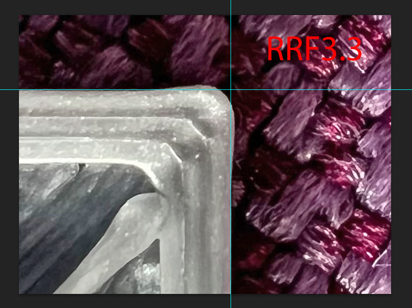
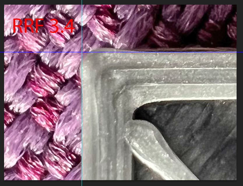
Difference is only marginal between both FW versions. My suspicious for now is the CAN toolboard.
@CCS86
Just print a small rectangle object with any filament and double the PA value you usually use. Infill lines won't connect with walls and also not within each other when using "Grid" filament type. Images from test prints are already in this thread from me. -
@argo said in Issues with pressure advance since RRF 3.4:
@CCS86
Just print a small rectangle object with any filament and double the PA value you usually use. Infill lines won't connect with walls and also not within each other when using "Grid" filament type. Images from test prints are already in this thread from me.Connect to the walls sure, because there are direction changes there, where PA is active. But, grid intersections some number of millimeters from a wall should not be affected.
-
-
I am having several issues with PA too.... The test using the python script have bulges AND under extrusion even on very high values of PA.
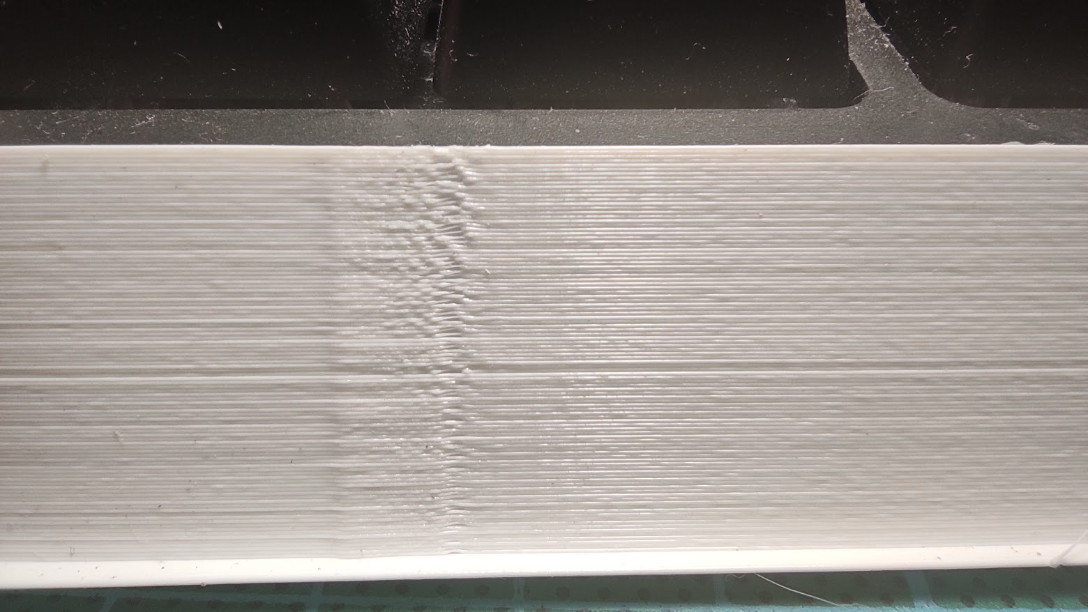
Here an example for PLA from 0.5 to 0.9 - The bulge NEVER disappear even when the under extrusion after starts to show.In the past there always a clear transition where the slow segments had the same width and no under extrusion after.
Also I simply cannot find a value of PA + Retract that lead to good results. It starts to to cause excessive retraction and blocking issues much before solving any oozing.
I reviewed all my hardware looking for possible issues and after finding this thread I think it is related.
It is very severe with small details and curved surfaces (like round small posts for retraction tuning) it is so severe that sometimes and entire layer is mission while others spurts excessive material. For straight lines - like a small cube walls - only the bulge is apparent and the under extrusion after the bulge for higher PA.
I had not updated my board for a long time and the issues started after the update to 3.4 - I do not remember what older version I had before.
But the issues are the same: Excess extrusion even with very high PA with under extrusion right after for higher PA. I had not of these issues before.
I will test 3.4.2 now and then roll back to 3.3 and repeat the Python script test to compare.
-
Ok... No differences at all from the same gcode from PA 0.5 to 1.3 with 3.3 and 3.4.2

-
@brunofporto How bout 3.2?
-
@brunofporto Are you using a toolboard, or other can-fd board to control the extruder?
-
@phaedrux I'll try!
-
@gloomyandy Nope. Duet 2 Ethernet v1.02 (the one before the on board fuses).
-
@brunofporto said in Issues with pressure advance since RRF 3.4:
Here an example for PLA from 0.5 to 0.9 - The bulge NEVER disappear even when the under extrusion after starts to show.
I'm looking forward to seeing your comparative results for RRF 3.3 and 3.4.2.
How long is the Bowden tube between the extruder drive and the hot end?
-
Small update for RRF 3.4.2. (stable) release.
PA was set to 0.052, printing PLA.
LDO Orbiter 2 extruder
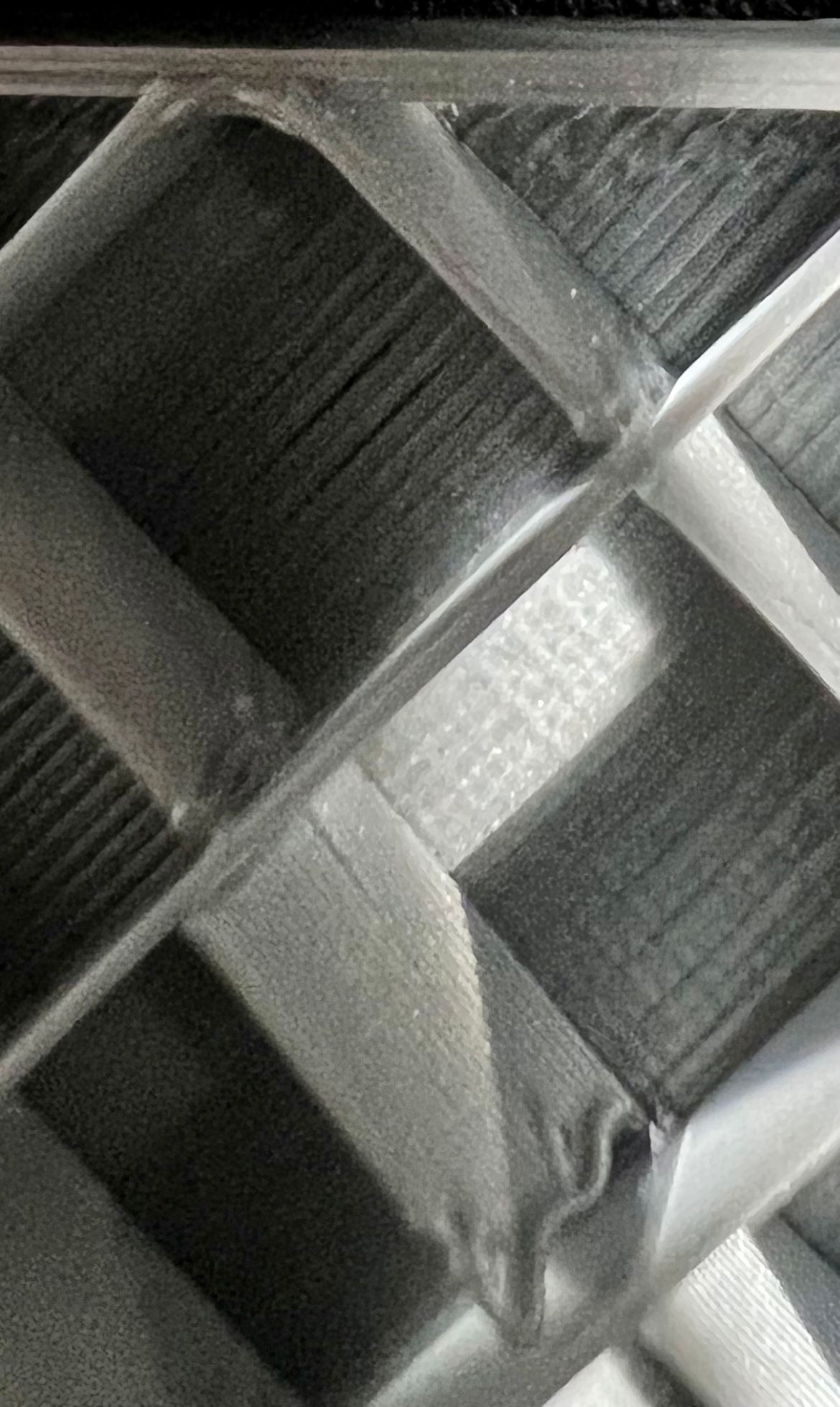
Input shaper ZVDD used (M593 P"zvdd" F40.5 S0.03)New test object (from a duet_rrf Voron channel user) to demonstrate the created overhang by the bulging corner which you can see when you flip it over:


-
@argo I'm not totally sure what it is we are looking at here. Can you post a picture that shows the full object partially from the side (rather than directly above) so we can get a better idea about the test print you have used?
-
Here's the object from another perspective. Imo it's a rather good test to see the actual material that overshoots when flipping the object. In my last post, when viewing the second picture in full screen you can see overshooting edge.

Second picture from last posting but cropped so you can see what I mean:
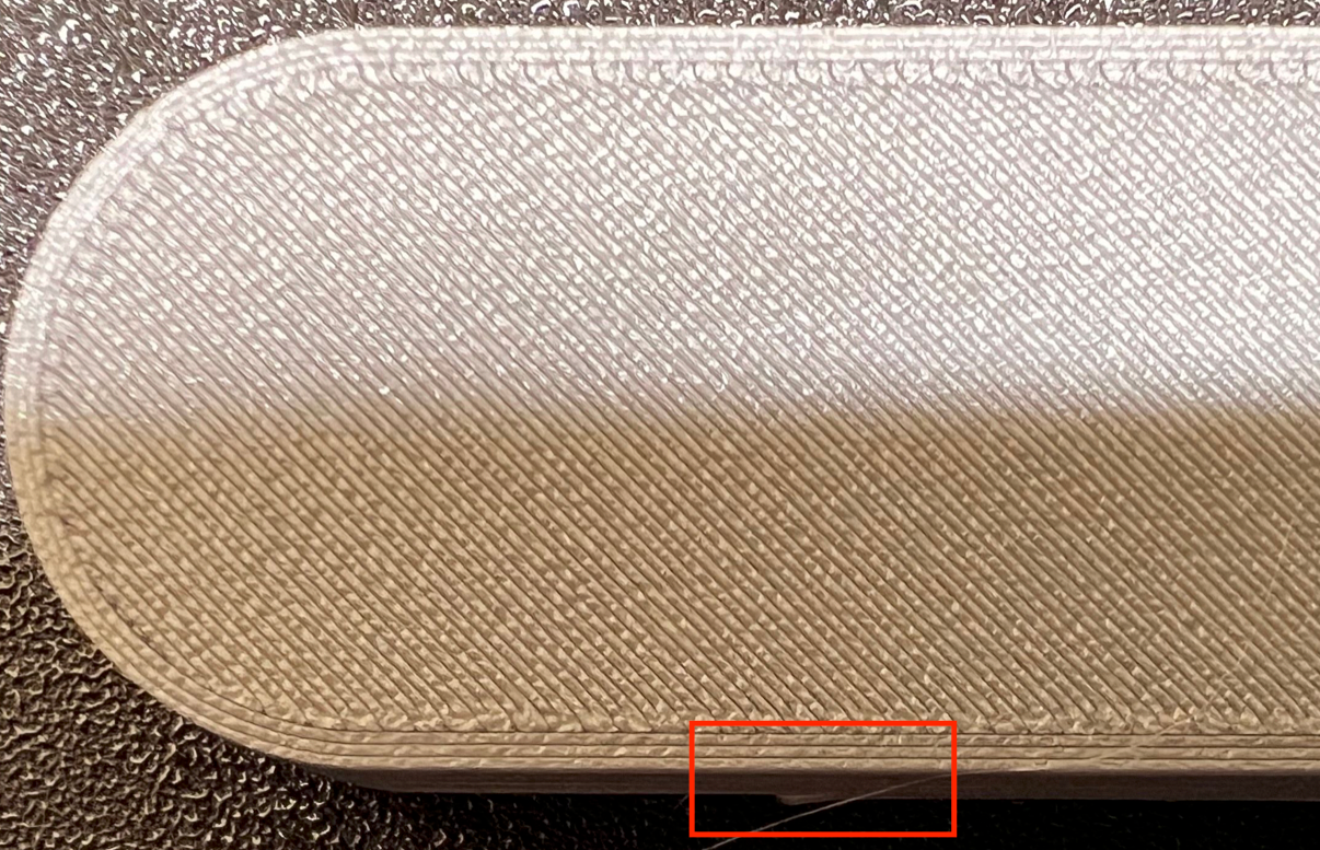
Unfortunately the bulging makes the printer unusable for me atm because I can only print round objects. For now the printer stays at RRF so I can share test prints when a new FW version gets released but I plan to move to Klipper in the near future (when I find the free time) if the issue remains.
Also the stl:
bulgecheck.stl -
@argo most slicers have a parameter to set the degree of overlap between infill and perimeters. What slicer are you using, and what overlap parameter?
