How many tools?
-
We are considering an update to our tool distribution board:
https://docs.duet3d.com/en/Duet3D_hardware/Duet_3_family/Duet_3_Tool_Distribution_BoardThe initial design was born out of the e3d toolchanger era so 4 tools just "made sense".
We have plans to change a bunch of things, the ZH connectors are fiddly and it does not have easy built in support for stubs, for example how its easiest to connect the roto toolboard on a stub.
One important question is how many tools per board.
I would love peoples feedback on this citing there own machine designs. current or future, on how many tools they have or plan to have per MACHINE. Potentially also think "CAN devices where a stub vs a daisy chain could be the way tis wired".
Given the prevalence of IDEX machines as soon as we go beyond a single tool, maybe a tool board that's easily daisy chained, that supports two tools, is the sweet spot?
-
The multi tool projects I am currently working on
Tool changer with 2 heads
Filament changer with 4, 6 and 12 bays
MISO 2,3,4 & 6 input 1 output = #x extruder motors on one extruder carriageWhat would be nice would be if the distro board could take the same XT30 2+2 so I don't need to splice power separately into the cable, or depending on the cable having to cut the other end off (if it has XT30 2+2 on both sides).
It might be nice to have the distro board being modular, so you can stack the boards if you need to add more ports without the mess of manually daisy chaining multiple together.
-
@Notepad so you would have XT30(2+2) at the distribution board end and the tool board end?
-
@T3P3Tony Yup. most of the cables I buy tend to be double ended. plus the cable being double ended reduces the risk (albeit very very small risk) of accidently wiring the cable wrong. I wouldn't say its a big improvement, and I could possibly argue its not an improvement at all. but having a single premade cable would look neater and be easier to just plug and play than 4 individual wires exiting a one sided XT30(2+2)
That and twisting the data pairs of individual wires by hand is an absolute ball ache. -
@Notepad i was comparing to say an TX30(2+2) at the tool board end and two JSTs at the distribution board end, for example. the JSTs are significantly easier for field termination, vs the XT30(2+2).
-
@T3P3Tony Your right, I forgot my bias! I tend to lean towards customer interactions when replacing the wires instead of hobbyist/makers. Soldering XT30s is certainly harder than crimping.
If the tiny JST ZHs are replaced with something bigger then it would already be a huge improvement. Crimping such small crimps is both a pain.How easy would it be to have both a XT30(2+2) header on the distribution board as well as JSTs? Something similar to the 6HC where it has the RJ11 port and the AUX_CAN JST right next to it? It might give a bit of flexibility to which approach a user wants to use.
-
@T3P3Tony I run a (mostly) standard e3d toolchanger with a Duet3 Mini and 4 toolboards off a distribution board (plus the 'tool' who runs it
 ), so probably fit the current setup quite well.
I've raised it before, so I'm glad to hear you're looking at the wiring-up side. The hardest part of setting up my toolboards was having to solder sleeve tiny ZH pigtails onto the CAN lines, then having to do it all again after I started having some random issues I attributed to a dodgy joint I couldn't find so replaced all of them. I get the need for a tiny connector on the toolboards, but the definitely not the distribution board end. Larger connectors like the main boards would mean most people could just crimp that end. Maybe it might make sense then to even provide long lengths of cables with ZH connectors on just one end for people to cut and crump to size?
Back to the main question... I'm not sure I could/would extend my machine past 4 tools. Maybe an extra board for some ancillaries like a wiper or the toolhead, but I would probably just wire that from the RJ connector on the distribution board and feed it power from one of the other boards. Or more lively rjn it straight from the mainboard if I had enough IO left.
-
@engikeneer said in How many tools?:
The hardest part of setting up my toolboards was having to solder sleeve tiny ZH pigtails onto the CAN lines
I find it easy using white solder sleeves like these https://www.amazon.co.uk/Connectors-Soldering-Connector-Waterproof-Electrical/dp/B0DK18MJHG with a hot air gun. I generally poke one of the wires in the correct distance, then heat just the glue ring of the sleeve around that wire to capture it. Then do the same with the other wire. Then heat the solder part in the middle.
However, I've had a few instances of pre-made ZH connectors with wire tails having bad crimps; so that is another reason to use something different. The XT30 2+2 connectors are great if both ends are pre-made, but a pain to solder otherwise.
-
@dc42 yeah thats exactly what I did (was following your blog post actually which was helpful!)
After doing 64 of them, making sure each of the pairs were soldered at the same length, with a reasonable twist left and didn't bunch up in an awkward place in the tool support, I got pretty good, but had burnt my fingers more times than i can count. At a typical labour rate, those cables would have cost more that all the Duet boards on the printer with how long I spent on them!
Having said that, the printer is much neater and better setup with the CAN boards. Being able to pull a complete tool off the printer by only pulling out 2 plugs and a couple of screws has been very handy at times. I certainly wouldn't go back to non-CAN in the future, but I would spend a fair amount of time (and money) to try and avoid the solder sleeves if it was building a new printer again. -
@Notepad said in How many tools?:
XT30
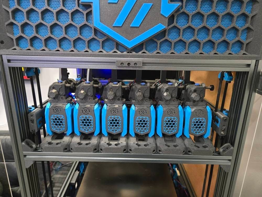
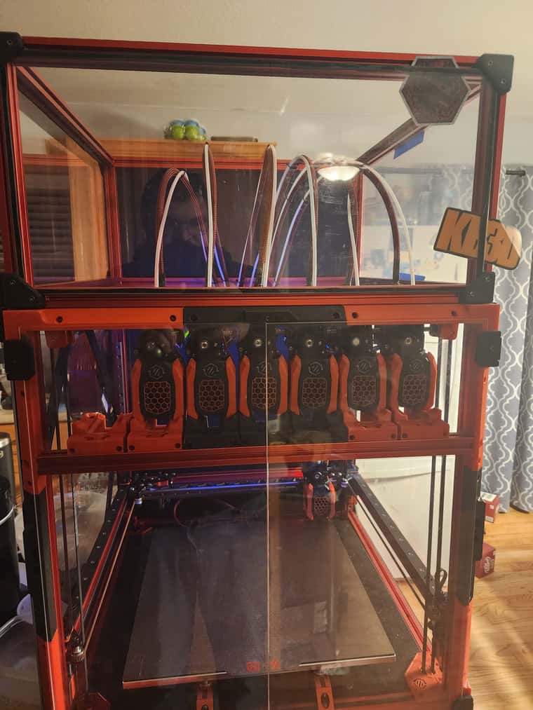
Just embarking on a toolc hanging setup on my Voron 2.4r2. Going with Stealthchanger. Most of the folks fully engaged in this endeavor are at minimum of 4 toolheads, and many have 5 or 6 - currently watching a V2.4 350mm build with 6 ANTHEAD toolhead possibly seven.
Seems 4 would be a minimum, 6 seems like a sweet spot. BLUE stuff isnt mine
 Rookie red stuff is ...


-
minimum of four tools for tool changer just seems to be an evolutionary inevitability to me. For two tools, IDEX is much easier to build and use (and you can make tool changes in less than two seconds with careful tuning). For three toolheads, its just not worth the added complexity and cost of machine space so four is the viable minimum and six/seven the viable maximum without enlarging the machine just to get more docking area ...
(yes, you can get a PrusaXL with one or two tools, but thats a business consideration).
-
@T3P3Tony USB connectors would be nice option for CAN and Power transfer.
-
@Aurimas IMO USB connectors are a terrible choice because someone will plug the wrong wires with rhe right connector in and then things will go splooey.
Also USB connections arent specced for motion, so having them on a toolboard invites them getting loose over time.
-
@oliof pretty much all others use them. I use them with my custom setup too and it works great.
-
@Aurimas whats wrong with the XT30 2+2 connect thats been adopted widely by the hobbyist market? AFAIK USB connectors are limited to 5A. No good for high powered tools etc
-
@Aurimas
No no USB is a horrible choice. The connectors are far to big and have my downsides for our usecase. And you need to use other wires anyway, the USB cables do not last long in chains.
Everything is better than this USB connectors. -
@jay_s_uk The XT30 2+x are nice, but that is the idea to get CAN out of the board than? A other connector? Solder pats?
-
@T3P3Tony I akes a while ago for a toolboard with more than one stepper connector too. That would help a lot when you build things like Enraged Rabbit or if you want to power a gantry with a can board.
To be honest: I would love to see more smaller and specialized tool boards.
Why not having a toolbaord which is specialized for a chamber heater? Just some outputs for SSRs and some temp sensors plus a servo?
Why not a board with 2 or 4 stepper drivers and 4-6 I/Os for endstops? (For gantries in a corexy)Or an toolboard just to control RGB Leds. And why not one like a daughter board which you can be stacked on the toolboard for the head?
And what is about a can multiplexer board? It would be nice to have more than 1 can bus in the system to make it more flexible. The stup setup is not ideal, you hit the 1m limit very easy.
I think that it is easy to come to more idea for boards which are dedicated to a very special usecase.
Cheers, Chriss
-
@Chriss said in How many tools?:
@jay_s_uk The XT30 2+x are nice, but that is the idea to get CAN out of the board than? A other connector? Solder pats?
The EXT30 2+2 are used as stubs normally.
-
@Chriss regardless how long they last - they are cheap, neat and super easy to replace.
Instead of running bunch of cables and having no quick disconnect option one cable is simpler.
Connectors big? Not sure where you got that