Duet3D Logo Duet3D
    • Tags
    • Documentation
    • Order
    • Register
    • Login
    1. Home
    2. AndreS
    3. Best
    • Profile
    • Following 0
    • Followers 3
    • Topics 11
    • Posts 87
    • Best 8
    • Controversial 0
    • Groups 0

    Best posts made by AndreS

    • PanelDue goes wireless

      Hi all,

      I had the idea to get rid of the cable from Duet to PanelDue (in my case to my own DuetMonitor with a Teensy and 5" RA8875 display), so I can place the Monitor where I want and even take it with me to another room (within reasons).
      I didnt want it to connect to my router and have read about the ESPNOW protocol. Its working on 2,4G frequency but is a (multi-)point to (multi-)point data transmission protocol without connection to a network.
      So I did some setup on a breadboard, and got a functioning prototype.
      Then I ordered some PCBs, soldered the components on and got this:
      0_1554812736310_IMG_20190406a.jpg
      0_1554812785470_IMG_20190406c.jpg
      0_1554812801920_IMG_20190406d.jpg
      Its working!! and no cable.

      The PCB is 3cm x 4cm. I went with a 18650 LiPo battery holder with charger, so no cable at all other then charging.
      Using and charging at the same time is possible with this battery holder.
      But you can go with this:
      0_1554813328852_IMG_20190409a.jpg
      mount it at the case and feed the voltage to the PCB. Power it with a wall wart or powerbank. A good powerbank should last several hours. The PanelDue gets the voltage through a short cable.
      The PCB on the printer should be mounted where it can receive and send proper.

      Because a panel of 4x4 PCBs was only a little more charge with p&p, now I have roughly 30 PCBs that I dont need.
      This is a great community, so if you want you can get them for €0,75 each + €1,50 postage to Europe and US (up to 50g), €3,70 above 50g (from Germany).
      The ESP8266 has to be programmed with Arduino IDE with ESP8266 Addon over serial. You can get the source code via email.

      Technical Data:
      You can choose between 8 IDs (Each pair has to have its own ID).
      You can choose between 4 WLAN channels (1,4,7,11).
      Set A or B for the ID. (There is no dedicated Master or Slave, each pair has one A and one B on the same ID and channel, and it doesnt matter which is on PanelDue and Duet side).
      The serial port can be set to 19200, 38400, 57600 or 115200. Typically set to 57600 for Duet.
      Its possible to use one PanelDue for different printers, but not at the same time: Change to another ID (and/or channel) on PanelDue side, press reset and you are connected to the other printer.

      If you are unable to solder and program the PCB I can do this, but I dont have the components laying around, so I have to order them.
      But it will then be €7 per PCB and I dont make a profit on it (I have no intention to make a profit).
      So if someone is interested PM me.

      And here is the schematic:
      0_1554814774874_SerialBridge_SCH.PDF

      posted in PanelDue
      AndreSundefined
      AndreS
    • RE: Z probe X/Y offset

      With G31

      posted in Tuning and tweaking
      AndreSundefined
      AndreS
    • RE: Delta printer recommendation with Duet2

      If you are up for an interesting delta design, take a look at this kickstarter campaign:
      Zatsit Delta
      Its a mechanical kit only.

      posted in 3D Printing General Chat
      AndreSundefined
      AndreS
    • RE: Firmware 2.03beta2 available

      @deckingman said in Firmware 2.03beta2 available:

      May I suggest that this input numbering vs label be included in the Wiki somewhere. Either in the section entitled "connecting end stop switches" or in the section dealing with M574. I don't think I trust myself to edit the Wiki personally but I'll have a go if you like.

      I have put it in with M574.

      posted in Firmware installation
      AndreSundefined
      AndreS
    • RE: Handling error codes to switch off power using M81

      I think it is not possible at the moment, but will be possible with the introduction of conditional execution of gcode in some of the next firmware releases.

      posted in General Discussion
      AndreSundefined
      AndreS
    • RE: RBGW Led + Duet Wifi (PWM pin or alternative board)

      I think the 2nd one will be more than adequate.

      posted in Duet Hardware and wiring
      AndreSundefined
      AndreS
    • RE: Responses on panelDue port

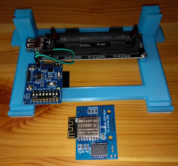
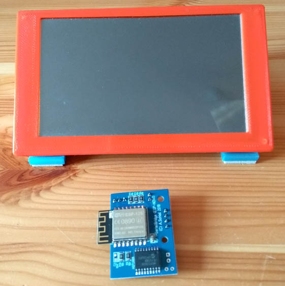
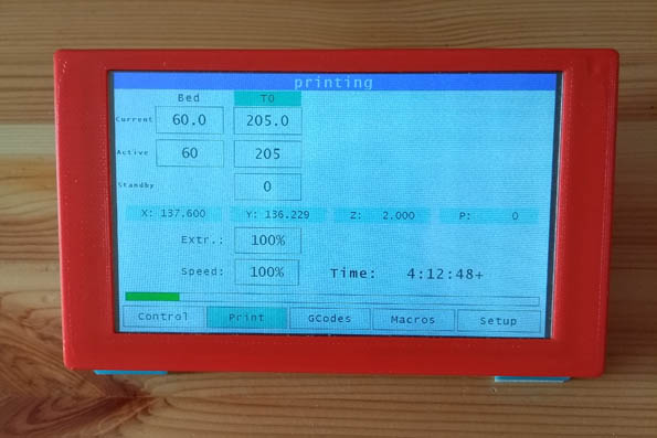
      No, i dont have a PanelDue. I made a little monitor myself. You can see it here https://www.duet3d.com/forum/thread.php?id=222. Its based on a Teensy 3.2 and a 2.8" display with touch.

      I adapted some code from the PanelDue source: json-parser (added code to receive no-json data lines), processing received values (only the structure) and sending commands with line-nr and checksum.
      It sends M408 with checksum and gets a response. Commands to set temperature are received on the Duet and acted on.
      Data in json-message and without json-format are displayed in a console-window.

      Yesterday I programmed a window to type in commands on a virtual keyboard and send them. At that time I had a M575 P1 B57600 S1 in config.g and the commands were send with checksum. If I send M140 S50 the bed will heat and G28 will home my delta. So commands are recognised. But M119 will get no response.

      For testing I set M575 P1 B57600 S0 in config.g and took out code to send line-nr and checksum.
      Behavior stays the same.
      I'm confused. Is the PanelDue sending some special characters? I searched in the source code but cound't find anything special.

      Some testing:
      I connected Duet via USB to my PC and opened a serial console for debugging.
      I send with my little Duetmonitor M111 P3 S1 and debugging is on. The message is also received on the Duetmonitor.
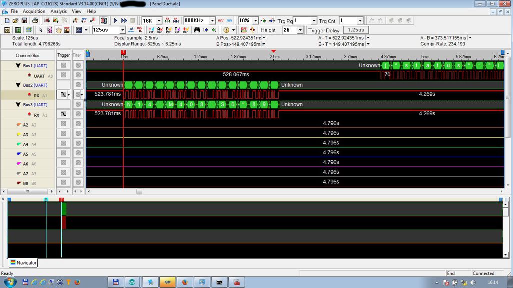
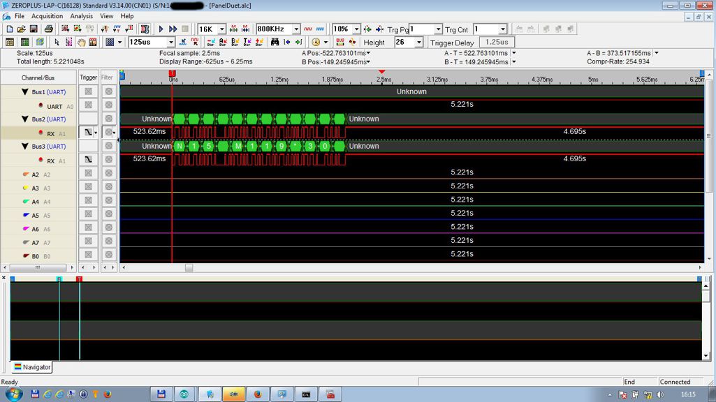
      Then I send M408 S0. The command is recognised and I have attached a screenshot from the logic analyser.
      Direct afterwards I send M119, and attached another screenshot, where you can see, that there is no response. In USB debugging both command are recognised.

      USB debugging:

      Debugging enabled for modules: GCodes(3)
      Debugging disabled for modules: Platform(0) Network(1) Webserver(2) Move(4) Heat(5) DDA(6) Roland(7) PrintMonitor(8) Storage(9)
      aux: N14 M408 S0*89
      aux: N15 M119*30
      Class GCodes spinning.


      Send M408 S0:

      Send M119:

      I attach my config.g so you can have a look if there is something interfering.

      ; Configuration file for Mini Kossel kit from Think3DPrint3D for Duet WiFi
      
      ; Communication and general
      M111 S0                             	; Debug off
      M550 PMiniKosselWiFi			; Machine name and Netbios name (can be anything you like)
      M551 Preprap                        	; Machine password (used for FTP)
      ;*** If you have more than one Duet on your network, they must all have different MAC addresses, so change the last digits
      M540 P0xBE:0xEF:0xDE:0xAD:0xFE:0xED 	; MAC Address
      ;*** Wifi Networking
      M552 S1					; Enable WiFi
      
      M555 P2                           	; Set output to look like Marlin
      M575 P1 B57600 S0			; Comms parameters for PanelDue
      
      G21                                 	; Work in millimetres
      G90                                	; Send absolute coordinates...
      M83                                 	; ...but relative extruder moves
      
      ; Axis and motor configuration
      M569 P0 S1				; Drive 0 goes forwards
      M569 P1 S1				; Drive 1 goes forwards
      M569 P2 S1				; Drive 2 goes forwards
      M569 P3 S0				; Drive 3 goes backwards (geared Extruder)
      M569 P4 S1				; Drive 4 goes forwards
      M574 X2 Y2 Z2 S1			; set endstop configuration (all endstops at high end, active high)
      ;M574 E1 S1
      
      ;*** The homed height is deliberately set too high in the following - you will adjust it during calibration
      M665 R101.56 L215.0 B85 H227.31		; set delta radius, diagonal rod length, printable radius and homed height
      M666 X0.05 Y0.14 Z-0.19			; put your endstop adjustments here, or let auto calibration find them
      M350 X16 Y16 E16 I1    			; Set 16x microstepping with interpolation
      M92 X80 Y80 Z80				; Set axis steps/mm
      M906 X1000 Y1000 Z1000 E800 I60		; Set motor currents (mA) and increase idle current to 60%
      M201 X1000 Y1000 Z1000 E1000		; Accelerations (mm/s^2)
      M203 X20000 Y20000 Z20000 E7200		; Maximum speeds (mm/min)
      M566 X800 Y800 Z800 E1200		; Maximum instant speed changes mm/minute
      
      ; Thermistors
      M305 P0 T100000 B3950 R4700 H0 L0	; Put your own H and/or L values here to set the bed thermistor ADC correction /H36
      M305 P1 T100000 B4388 R4700 H0 L0	; Put your own H and/or L values here to set the first nozzle thermistor ADC correction /H20
      M305 P2 T100000 B4388 R4700 H0 L0	; Put your own H and/or L values here to set the second nozzle thermistor ADC correction
      ;M570 S180				; Hot end may be a little slow to heat up so allow it 180 seconds
      
      ; Fans
      M106 I0 				; fans are not inverting
      M106 S0 				; Turn off Fan 0
      M106 P1 F100
      M106 P1 H-1 				; disable thermostatic mode for fan 1
      M106 P1 S0
      M106 P2 I1 H-1 F87			; disable thermostatic mode for LEDs, set PWM frequency, output inverted
      M106 P2 S0.15				; LEDs on at 15%
      
      ; Tool definitions
      M563 P0 D0 H1                       	; Define tool 0
      G10 P0 S0 R0                        	; Set tool 0 operating and standby temperatures
      ;*** If you have a single-nozzle build, comment the next 2 lines
      ;M563 P1 H2                      	; Define tool 1
      ;G10 P1 S0 R0                       	; Set tool 1 operating and standby temperatures
      
      M92 E695                       		; Set extruder steps per mm (100 / gemessener Vorschub * aktuelle Steps)
      
      ; Z probe and compensation definition
      ;*** If you have a switch instead of an IR probe, change P1 to P4 in the following M558 command
      M558 P5 X0 Y0 Z0			; Z probe is hall sensor and is not used for homing any axes
      G31 X0 Y0 Z-0.15 P500			; Set the zprobe height and threshold (put your own values here)
      
      ;*** If you are using axis compensation, put the figures in the following command
      M556 S78 X0 Y0 Z0                   	; Axis compensation here
      
      M208 S1 Z0.0				; set minimum Z
      M207 S3.5 F4500 Z0.1			; set hardware-retraction
      M572 D0 S0.15				; set extruder advance
      
      M307 H0 A87.3 C285.3 D8.3 B0		; set bed heater model
      ;
      T0					; select first hot end
      
      
      posted in Firmware wishlist
      AndreSundefined
      AndreS
    • RE: 3144 5V Hall Sensors on duet?

      Hey, i was writing a ton of text and now had to delete it 🙂
      Do as @dc42 suggested, should work.
      The SS49E has an analog output and is in its raw form not suitable as endstop.

      posted in Duet Hardware and wiring
      AndreSundefined
      AndreS