Duet3D Logo Duet3D
    • Tags
    • Documentation
    • Order
    • Register
    • Login
    1. Home
    2. Bluemalu
    • Profile
    • Following 1
    • Followers 0
    • Topics 12
    • Posts 30
    • Best 3
    • Controversial 0
    • Groups 0

    Bluemalu

    @Bluemalu

    3
    Reputation
    3
    Profile views
    30
    Posts
    0
    Followers
    1
    Following
    Joined Last Online

    Bluemalu Unfollow Follow

    Best posts made by Bluemalu

    • RE: PanelDue5i - not communicating

      Sorted, many thanks. Not exactly sure what I did differently this time but I ended up with a different result - PanelDue5i is working!

      When I removed the unit I checked the cable and during my belling out a crimp popped out, the connection looked fine but when I tested it it showed open circuit, 50/50 chance for where the bad end was and I lost, it was the end on the motherboard end. Two crimps later and a firmware update and all good.

      Tomorrow is calibration of extruders and fun with bed levelling.

      posted in PanelDue
      Bluemaluundefined
      Bluemalu
    • RE: 3 spehre/point Delta ("Spiderbot")?

      I think the easiest answer is all of the issues related to Cartesian printers and movements were solved with pen plotters and dot matrix printers. Big companies have been able to produce the most efficient and cheap way to solve the issues so other than a moving Z platform it's virtually plug and play. Also, as I stated previously the processing power to control 4 stepper motors was right at the limit for 8 bit boards. Another disadvantage is the size of the machine, it has to be much taller than the equivalent sized cartesian due to movement required for the edges of the bed, also the bed is round rather than square / rectangular.

      The Kinematic control of the head has caught up now so it's lovely and smooth, by design the head will be horizontal (although I did read of paper where they had printed in a terrain following method for the top layers, just required knowledge of the head shape to avoid clashes - this was a few years ago and I can't find any further work carried out - maybe Simplify3D V5 🙂

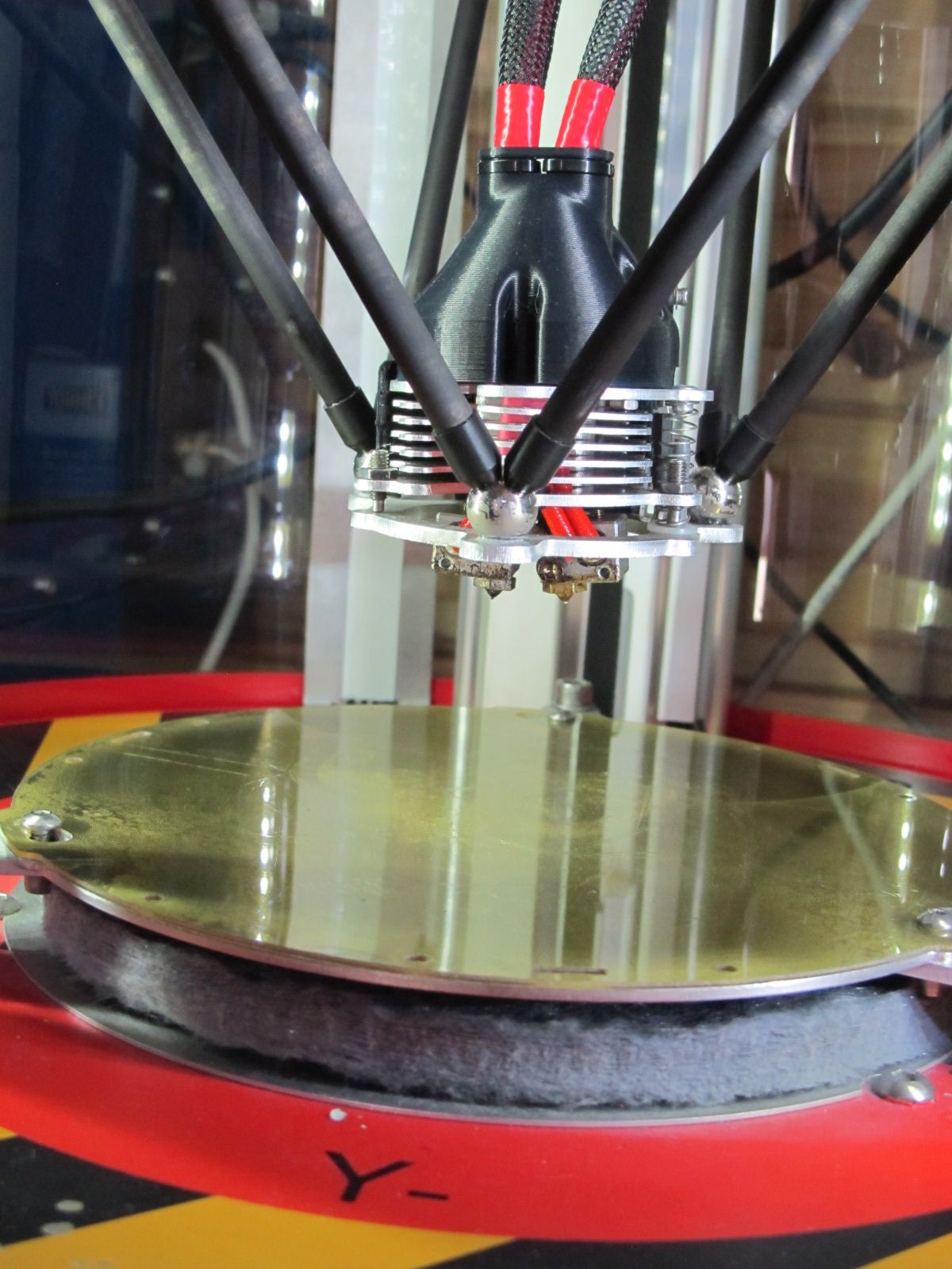
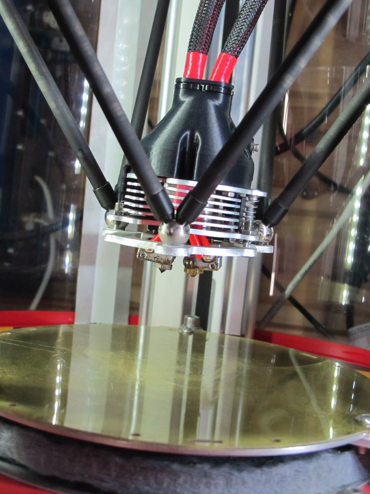
      My SpiderBot is the V1.5 with various upgrades through SpiderBot and the prototype dual head. Attached are a couple of pictures, maybe best to have them side by side as the cantilever of the head via the servo is subtle but is an elegant solution to dual head woes (one of my other printers is the BigBox Dual with print heads the same height so I'm used to suffering the issues with the 1st layer).

      [http://www.spiderbot.eu/spiderbot-v2-1-whats-new/?lang=en](link url)

      SpiderBot - Tool 1.JPG SpiderBot - Tool 0.JPG

      The original design used ball bearings secured with epoxy, as the printer is used with a heated chamber this heat cycling (or my cold shed) caused them to fall off. Philippe (owner of SpiderBot) improved the design by riveting the balls onto the aluminium.

      I'm more than happy with mine and the assistance I've had over the years for SpiderBot, it just doesn't get used as much due to having multiple printers and not using ABS.

      It's well worth having a nosey though the older blog articles to see the engineering iterations leading up to the latest versions.

      posted in 3D Printing General Chat
      Bluemaluundefined
      Bluemalu
    • Is there an issue with the configurator?

      Is there an issue with

      https://configtool.reprapfirmware.org

      It now gives me a 404 error or sends me to https://sackinima.com/forums/

      posted in General Discussion
      Bluemaluundefined
      Bluemalu

    Latest posts made by Bluemalu

    • RE: Delta effector constant tilt

      Couple of silly questions from a SpiderBot owner.

      (1) If you remove and rotate the effector 120 degrees does the tilt move?
      (2) In your arms have you got the magnets polarised ( all the Norths at either the effector or the axis - NB might not be an issue for this effector as the arms don't share the same spheres like the SpiderBot.
      (3) You've checked the horizontal plane, are your guides perpendicular (90 degrees to the chosen plane (normally the bed - beware it may move slightly if heated) - Engineers square is useful in this respect.
      (4) I see the measurements are written on your arms, just check the inside of them for debris as I suspect they are cupped and small amounts of debris can be picked up from the bearing surface.
      (5) I use a squirt of dry PTFE spray on my bearings, if you haven't got any dry spray - summer dry bike chain lube isn't too bad.

      posted in Smart effector for delta printers
      Bluemaluundefined
      Bluemalu
    • RE: 3 spehre/point Delta ("Spiderbot")?

      I think the easiest answer is all of the issues related to Cartesian printers and movements were solved with pen plotters and dot matrix printers. Big companies have been able to produce the most efficient and cheap way to solve the issues so other than a moving Z platform it's virtually plug and play. Also, as I stated previously the processing power to control 4 stepper motors was right at the limit for 8 bit boards. Another disadvantage is the size of the machine, it has to be much taller than the equivalent sized cartesian due to movement required for the edges of the bed, also the bed is round rather than square / rectangular.

      The Kinematic control of the head has caught up now so it's lovely and smooth, by design the head will be horizontal (although I did read of paper where they had printed in a terrain following method for the top layers, just required knowledge of the head shape to avoid clashes - this was a few years ago and I can't find any further work carried out - maybe Simplify3D V5 🙂

      My SpiderBot is the V1.5 with various upgrades through SpiderBot and the prototype dual head. Attached are a couple of pictures, maybe best to have them side by side as the cantilever of the head via the servo is subtle but is an elegant solution to dual head woes (one of my other printers is the BigBox Dual with print heads the same height so I'm used to suffering the issues with the 1st layer).

      [http://www.spiderbot.eu/spiderbot-v2-1-whats-new/?lang=en](link url)

      SpiderBot - Tool 1.JPG SpiderBot - Tool 0.JPG

      The original design used ball bearings secured with epoxy, as the printer is used with a heated chamber this heat cycling (or my cold shed) caused them to fall off. Philippe (owner of SpiderBot) improved the design by riveting the balls onto the aluminium.

      I'm more than happy with mine and the assistance I've had over the years for SpiderBot, it just doesn't get used as much due to having multiple printers and not using ABS.

      It's well worth having a nosey though the older blog articles to see the engineering iterations leading up to the latest versions.

      posted in 3D Printing General Chat
      Bluemaluundefined
      Bluemalu
    • RE: 3 spehre/point Delta ("Spiderbot")?

      Forgot to say, my 2nd printer was the SpiderBot.

      posted in 3D Printing General Chat
      Bluemaluundefined
      Bluemalu
    • RE: 3 spehre/point Delta ("Spiderbot")?

      Hope I can help, my first printer was the SeeMeCNC Rostock MAX built up as a kit as I wanted to build a different printer from the standard cartesian ones (and also when it prints it has a very satisfying hypnotic movement). Lets just say the original Rostock MAX had plenty of issues but a great kit for learning from.

      I was going to build my own but like you found the SpiderBot website many years ago and it's construction ticked all my boxes for accuracy and quality. Also, the heated chamber for ABS was a plus (this was in the days before PETG).

      The biggest failing was the hardware, with a delta three stepper motors have to be driven for the axis all the time and one for the extruder. The SpiderBot had a Megatronix 8 bit board that was close to it's limits. I upgraded mine with the ultratronics (this was the 32 bit version). This upgrade of computation power was in my opinion essential for a delta.

      SpiderBot also came up with a novel dual head (using a servo to cant the head) which makes printing with HIPS and ABS easy. Unfortunately, now we have PETG the SpiderBot doesn't get as much work as the ABS has a distinct odour.

      The carbon fibre arms all manufactured identical lengths on a press with the ball bearings makes it more accurate than the Rostock which was rather flimsy.

      If there is anything specific I can help with just let me know

      posted in 3D Printing General Chat
      Bluemaluundefined
      Bluemalu
    • RE: Adding sprinkles - Extruder feed rate / Acceleration Tuning

      @Phaedrux - That makes sense, I used G91 not M83 although M83 is in my config.g. I'll have a read up on the M204 and get it added in.

      posted in Tuning and tweaking
      Bluemaluundefined
      Bluemalu
    • Adding sprinkles - Extruder feed rate / Acceleration Tuning

      Having successfully transplanted a Duet3 6HC (3.1.1) / PanelDue5i (1.24) and RPI into my BigBox dual printer I'm now getting to what I hope is the end of the testing / calibration. I've been using

      https://teachingtechyt.github.io/calibration.html#intro

      I'm now up to the final 2 steps which I never used on my old RUMBA based board and I've had a couple of issue and would like some guidance please.

      (1) Extruders are E3D V6 (1.75mm / PETG / 240 degrees) with 0.4mm nozzles- when I try to use G1 E50 F180 it extrudes fine, when I increase the speed to G1 E50 F240 it clogs. However, when I use the inbuilt extrude function at 10mm/s => F600 it works fine. Am I getting my metrics mixed up? Does the extrude function take into account acceleration / flow rate. When I try 20mm/s it struggles which is what I'd expect as I've seen various quotes of around 15 mm/s max.

      (2) This leads me onto acceleration tuning, I've not got any advanced settings set up, which method is the one to use as I've not set an M205.

      config.g

      posted in Tuning and tweaking
      Bluemaluundefined
      Bluemalu
    • RE: Issues with new Duet@

      If the PanelDue powers up - ie displays something don't make the mistake I made and press the buttons on the panel and erase the firmware. If you do it's fairly easy to upload the firmware using Bossa and the USB connector.

      https://duet3d.dozuki.com/Wiki/Connecting_an_LCD_control_panel#Section_Connecting_a_PanelDue

      After I had the screen displaying information it sat on a screen saying connecting. I changed out the cable for a 2nd one, still had the same issue. Turned out a poor crimp on the connectors that failed only when plugged in. Very annoying fault.

      posted in Duet Hardware and wiring
      Bluemaluundefined
      Bluemalu
    • RE: Housekeeping - Config.g for dual Z - where did I go wrong?

      @jay_s_uk - Perfect - All happy now, just re-running my bed heater calibration to compare with the first set of readings.

      posted in Tuning and tweaking
      Bluemaluundefined
      Bluemalu
    • Housekeeping - Config.g for dual Z - where did I go wrong?

      Hello again,

      I've completed my setup and am happy with everything but the RRF Config tool doesn't reflect my system correctly, so I decided to try and clean up the code - NB: The generated code from the RRF works.

      RRF Config.g

      ; Configuration file for Duet 3 (firmware version 3)
      ; executed by the firmware on start-up
      ;
      ; generated by RepRapFirmware Configuration Tool v3.1.4 on Mon Oct 26 2020 16:22:11 GMT+0000 (Greenwich Mean Time)
      
      ; General preferences
      G90                                                    ; send absolute coordinates...
      M83                                                    ; ...but relative extruder moves
      M550 P"Duet 3"                                         ; set printer name
      
      ; Drives
      M569 P0.0 S1                                           ; physical drive 0.0 goes forwards
      M569 P0.1 S0                                           ; physical drive 0.1 goes backwards
      M569 P0.2 S0                                           ; physical drive 0.2 goes backwards
      M569 P0.3 S0                                           ; physical drive 0.3 goes backwards
      M569 P0.4 S1                                           ; physical drive 0.4 goes forwards
      M569 P0.5 S0                                           ; physical drive 0.5 goes backwards
      M584 X0.0 Y0.1 Z0.2 E0.3:0.4:0.5                       ; set drive mapping
      M350 X16 Y16 Z16 E16:16:16 I1                          ; configure microstepping with interpolation
      M92 X160.00 Y360.00 Z800.00 E800.00:304.00:304.00      ; set steps per mm
      M566 X900.00 Y900.00 Z60.00 E60.00:120.00:120.00       ; set maximum instantaneous speed changes (mm/min)
      M203 X9000.00 Y9000.00 Z600.00 E600.00:4500.00:4500.00 ; set maximum speeds (mm/min)
      M201 X800.00 Y800.00 Z20.00 E20.00:1000.00:100.00      ; set accelerations (mm/s^2)
      M906 X1360 Y1600 Z1344 E1344:1360:1360 I30             ; set motor currents (mA) and motor idle factor in per cent
      M84 S30                                                ; Set idle timeout
      
      ; Axis Limits
      M208 X0 Y0 Z0 S1                                       ; set axis minima
      M208 X260 Y240 Z280 S0                                 ; set axis maxima
      
      ; Endstops
      M574 X1 S1 P"io1.in"                                   ; configure active-high endstop for low end on X via pin io1.in
      M574 Y1 S1 P"io2.in"                                   ; configure active-high endstop for low end on Y via pin io2.in
      M574 Z1 S2                                             ; configure Z-probe endstop for low end on Z
      
      ; Z-Probe
      M558 P1 C"io3.in" H5 F120 T6000                        ; set Z probe type to unmodulated and the dive height + speeds
      G31 P500 X0 Y0 Z1.888                                  ; set Z probe trigger value, offset and trigger height
      M557 X0:240 Y0:160 S40                                 ; define mesh grid
      
      ; Heaters
      M308 S0 P"temp0" Y"thermistor" T100000 B4267           ; configure sensor 0 as thermistor on pin temp0
      M950 H0 C"out0" T0                                     ; create bed heater output on out0 and map it to sensor 0
      M307 H0 B0 S1.00                                       ; disable bang-bang mode for the bed heater and set PWM limit
      M140 H0                                                ; map heated bed to heater 0
      M143 H0 S120                                           ; set temperature limit for heater 0 to 120C
      M308 S1 P"spi.cs0" Y"rtd-max31865"                     ; configure sensor 1 as thermocouple via CS pin spi.cs0
      M950 H1 C"out1" T1                                     ; create nozzle heater output on out1 and map it to sensor 1
      M307 H1 B0 S1.00                                       ; disable bang-bang mode for heater  and set PWM limit
      M308 S2 P"spi.cs1" Y"rtd-max31865"                     ; configure sensor 2 as thermocouple via CS pin spi.cs1
      M950 H2 C"out2" T2                                     ; create nozzle heater output on out2 and map it to sensor 2
      M307 H2 B0 S1.00                                       ; disable bang-bang mode for heater  and set PWM limit
      
      ; Fans
      M950 F0 C"out7" Q500                                   ; create fan 0 on pin out7 and set its frequency
      M106 P0 S1 H-1                                         ; set fan 0 value. Thermostatic control is turned off
      M950 F1 C"out8" Q500                                   ; create fan 1 on pin out8 and set its frequency
      M106 P1 S1 H-1                                         ; set fan 1 value. Thermostatic control is turned off
      M950 F2 C"out4" Q500                                   ; create fan 2 on pin out4 and set its frequency
      M106 P2 S1 H1 T45                                      ; set fan 2 value. Thermostatic control is turned on
      M950 F3 C"out5" Q500                                   ; create fan 3 on pin out5 and set its frequency
      M106 P3 S1 H2 T45                                      ; set fan 3 value. Thermostatic control is turned on
      M950 F4 C"out9" Q65535                                 ; create fan 4 on pin out9 and set its frequency
      M106 P4 S1 H1:2 T45                                    ; set fan 4 value. Thermostatic control is turned on
      
      ; Tools
      M563 P0 S"Left Extruder" D0 H1 F0                      ; define tool 0
      G10 P0 X0 Y0 Z0                                        ; set tool 0 axis offsets
      G10 P0 R0 S0                                           ; set initial tool 0 active and standby temperatures to 0C
      M563 P1 S"Right Extruder" D1 H2 F1                     ; define tool 1
      G10 P1 X0 Y0 Z0                                        ; set tool 1 axis offsets
      G10 P1 R0 S0                                           ; set initial tool 1 active and standby temperatures to 0C
      
      ; Custom settings
      M584 X0 Y1 Z2:3 E4:5                                   ; Driver 0 controls the X motor, 1 controls Y, 2 and 3 control Z motors, 4 and 5 control E motors
      M671 X-35:335 Y100:100                                 ; Define positions of Z Axis lead screws
      
      M307 H0 A233.6 C1178.2 D0.5 V24.1 B0                   ; Heated Bed Calibration 26/10/20
      M307 H1 A327.8 C161.2 D2.8 V24.2 B0                    ; Left Extruder Heater Calibration 17/10/20
      M307 H2 A325.8 C160.8 D3.4 V24.2 B0                    ; Right Extruder Heater Calibration 17/10/20
      
      M106 P0 S0                                             ; Turn Fan 0 OFF
      M106 P1 S0                                             ; Turn Fan 1 OFF
      
      ; Miscellaneous
      M575 P1 S1 B57600                                      ; enable support for PanelDue
      T0                                                     ; select first tool
      

      And bed.g (for completeness, no actual issues)

      ; bed.g
      ; called to perform automatic bed compensation via G32
      ;
      ; Setup for bed levelling using multiple independent Z motors
      
      G28 ; Home
      G30 P0 X0   Y100 Z-99999    ; Z probe Left side lead screw
      G30 P1 X255 Y100 Z-99999 S2 ; Z probe Right side lead screw
      
      
      ;M561 ; clear any bed transform
      ;G29  ; probe the bed and enable compensation
      

      Finally my code, with the main change tidying up around the M584 area to reflect the extra Z drive, I've modified the lines below it to reflect the shuffling around.

      ; Configuration file for Duet 3 (firmware version 3)
      ; executed by the firmware on start-up
      ;
      ; BigBox Dual - Z and Extruders
      
      ; General preferences
      G90                                                    ; send absolute coordinates...
      M83                                                    ; ...but relative extruder moves
      M550 P"Duet 3"                                         ; set printer name
      
      ; Drives
      M569 P0.0 S1                                           ; physical drive 0.0 goes forwards
      M569 P0.1 S0                                           ; physical drive 0.1 goes backwards
      M569 P0.2 S0                                           ; physical drive 0.2 goes backwards
      M569 P0.3 S0                                           ; physical drive 0.3 goes backwards
      M569 P0.4 S1                                           ; physical drive 0.4 goes forwards
      M569 P0.5 S0                                           ; physical drive 0.5 goes backwards
      M584 X0.0 Y0.1 Z0.2:0.3 E0.4:0.5                       ; set drive mapping X,Y,Z0,Z1,E0,E1
      M350 X16 Y16 Z16:16 E16:16 I1                          ; configure microstepping with interpolation
      M92 X160.00 Y360.00 Z800.00:800.00 E304.00:304.00      ; set steps per mm
      M566 X900.00 Y900.00 Z60.00:60.00 E120.00:120.00       ; set maximum instantaneous speed changes (mm/min)
      M203 X9000.00 Y9000.00 Z600.00:600.00 E4500.00:4500.00 ; set maximum speeds (mm/min)
      M201 X800.00 Y800.00 Z20.00:20.00 E1000.00:1000.00     ; set accelerations (mm/s^2)
      M906 X1360 Y1600 Z1344:1344 E1360:1360 I30             ; set motor currents (mA) and motor idle factor in per cent
      M84 S30                                                ; Set idle timeout
      
      ; Axis Limits
      M208 X0 Y0 Z0 S1                                       ; set axis minima
      M208 X260 Y240 Z280 S0                                 ; set axis maxima
      
      ; Endstops
      M574 X1 S1 P"io1.in"                                   ; configure active-high endstop for low end on X via pin io1.in
      M574 Y1 S1 P"io2.in"                                   ; configure active-high endstop for low end on Y via pin io2.in
      M574 Z1 S2                                             ; configure Z-probe endstop for low end on Z
      
      ; Z-Probe
      M558 P1 C"io3.in" H5 F120 T6000                        ; set Z probe type to unmodulated and the dive height + speeds
      G31 P500 X0 Y0 Z1.888                                  ; set Z probe trigger value, offset and trigger height
      M557 X0:240 Y0:160 S40                                 ; define mesh grid
      
      ; Heaters
      M308 S0 P"temp0" Y"thermistor" T100000 B4267           ; configure sensor 0 as thermistor on pin temp0
      M950 H0 C"out0" T0                                     ; create bed heater output on out0 and map it to sensor 0
      M307 H0 B0 S1.00                                       ; disable bang-bang mode for the bed heater and set PWM limit
      M140 H0                                                ; map heated bed to heater 0
      M143 H0 S120                                           ; set temperature limit for heater 0 to 120C
      M308 S1 P"spi.cs0" Y"rtd-max31865"                     ; configure sensor 1 as thermocouple via CS pin spi.cs0
      M950 H1 C"out1" T1                                     ; create nozzle heater output on out1 and map it to sensor 1
      M307 H1 B0 S1.00                                       ; disable bang-bang mode for heater  and set PWM limit
      M308 S2 P"spi.cs1" Y"rtd-max31865"                     ; configure sensor 2 as thermocouple via CS pin spi.cs1
      M950 H2 C"out2" T2                                     ; create nozzle heater output on out2 and map it to sensor 2
      M307 H2 B0 S1.00                                       ; disable bang-bang mode for heater  and set PWM limit
      
      ; Fans
      M950 F0 C"out7" Q500                                   ; create fan 0 on pin out7 and set its frequency
      M106 P0 S1 H-1                                         ; set fan 0 value. Thermostatic control is turned off
      M950 F1 C"out8" Q500                                   ; create fan 1 on pin out8 and set its frequency
      M106 P1 S1 H-1                                         ; set fan 1 value. Thermostatic control is turned off
      M950 F2 C"out4" Q500                                   ; create fan 2 on pin out4 and set its frequency
      M106 P2 S1 H1 T45                                      ; set fan 2 value. Thermostatic control is turned on
      M950 F3 C"out5" Q500                                   ; create fan 3 on pin out5 and set its frequency
      M106 P3 S1 H2 T45                                      ; set fan 3 value. Thermostatic control is turned on
      M950 F4 C"out9" Q65535                                 ; create fan 4 on pin out9 and set its frequency
      M106 P4 S1 H1:2 T45                                    ; set fan 4 value. Thermostatic control is turned on
      
      ; Tools
      M563 P0 S"Left Extruder" D0 H1 F0                      ; define tool 0
      G10 P0 X0 Y0 Z0                                        ; set tool 0 axis offsets
      G10 P0 R0 S0                                           ; set initial tool 0 active and standby temperatures to 0C
      M563 P1 S"Right Extruder" D1 H2 F1                     ; define tool 1
      G10 P1 X0 Y0 Z0                                        ; set tool 1 axis offsets
      G10 P1 R0 S0                                           ; set initial tool 1 active and standby temperatures to 0C
      
      ; Custom settings
      
      M671 X-35:335 Y100:100                                 ; Define positions of Z Axis lead screws
      
      M307 H0 A233.6 C1178.2 D0.5 V24.1 B0                   ; Heated Bed Calibration 26/10/20
      M307 H1 A327.8 C161.2 D2.8 V24.2 B0                    ; Left Extruder Heater Calibration 17/10/20
      M307 H2 A325.8 C160.8 D3.4 V24.2 B0                    ; Right Extruder Heater Calibration 17/10/20
      
      M106 P0 S0                                             ; Turn Fan 0 OFF
      M106 P1 S0                                             ; Turn Fan 1 OFF
      
      ; Miscellaneous
      M575 P1 S1 B57600                                      ; enable support for PanelDue
      T0                                                     ; select first tool
      

      When I install my config.g I get 3 warinings:-

      0fa8f2ad-7394-47a5-92f9-539a4528542d-image.png

      The (M55) hostname, I'm not sure about as I've never changed it from the default.
      The M350 seems to be the issue but I'm not sure why? I've checked the RepRap G-Code and it looks correct. I've tried using my M584 declaration without the 0. before the drives (as per custom setting), unfortunately to no avail.

      The (M307) heater seating is from the PID's calculated during the calibration of heated plate.

      I'm inclined just to carry on with what I have but have the curse of the Engineer in just knowing what I've done wrong / missed.

      posted in Tuning and tweaking
      Bluemaluundefined
      Bluemalu
    • RE: Dual Z Motors single Z Probe as end stop for each motor

      Perfect, bed is a piece of 6mm tooling aluminium with little flex so no point in over egging the pudding.

      Time to start printing as that was my last query from my upgrade.

      posted in Firmware installation
      Bluemaluundefined
      Bluemalu