Hello again,
I've completed my setup and am happy with everything but the RRF Config tool doesn't reflect my system correctly, so I decided to try and clean up the code - NB: The generated code from the RRF works.
RRF Config.g
; Configuration file for Duet 3 (firmware version 3)
; executed by the firmware on start-up
;
; generated by RepRapFirmware Configuration Tool v3.1.4 on Mon Oct 26 2020 16:22:11 GMT+0000 (Greenwich Mean Time)
; General preferences
G90 ; send absolute coordinates...
M83 ; ...but relative extruder moves
M550 P"Duet 3" ; set printer name
; Drives
M569 P0.0 S1 ; physical drive 0.0 goes forwards
M569 P0.1 S0 ; physical drive 0.1 goes backwards
M569 P0.2 S0 ; physical drive 0.2 goes backwards
M569 P0.3 S0 ; physical drive 0.3 goes backwards
M569 P0.4 S1 ; physical drive 0.4 goes forwards
M569 P0.5 S0 ; physical drive 0.5 goes backwards
M584 X0.0 Y0.1 Z0.2 E0.3:0.4:0.5 ; set drive mapping
M350 X16 Y16 Z16 E16:16:16 I1 ; configure microstepping with interpolation
M92 X160.00 Y360.00 Z800.00 E800.00:304.00:304.00 ; set steps per mm
M566 X900.00 Y900.00 Z60.00 E60.00:120.00:120.00 ; set maximum instantaneous speed changes (mm/min)
M203 X9000.00 Y9000.00 Z600.00 E600.00:4500.00:4500.00 ; set maximum speeds (mm/min)
M201 X800.00 Y800.00 Z20.00 E20.00:1000.00:100.00 ; set accelerations (mm/s^2)
M906 X1360 Y1600 Z1344 E1344:1360:1360 I30 ; set motor currents (mA) and motor idle factor in per cent
M84 S30 ; Set idle timeout
; Axis Limits
M208 X0 Y0 Z0 S1 ; set axis minima
M208 X260 Y240 Z280 S0 ; set axis maxima
; Endstops
M574 X1 S1 P"io1.in" ; configure active-high endstop for low end on X via pin io1.in
M574 Y1 S1 P"io2.in" ; configure active-high endstop for low end on Y via pin io2.in
M574 Z1 S2 ; configure Z-probe endstop for low end on Z
; Z-Probe
M558 P1 C"io3.in" H5 F120 T6000 ; set Z probe type to unmodulated and the dive height + speeds
G31 P500 X0 Y0 Z1.888 ; set Z probe trigger value, offset and trigger height
M557 X0:240 Y0:160 S40 ; define mesh grid
; Heaters
M308 S0 P"temp0" Y"thermistor" T100000 B4267 ; configure sensor 0 as thermistor on pin temp0
M950 H0 C"out0" T0 ; create bed heater output on out0 and map it to sensor 0
M307 H0 B0 S1.00 ; disable bang-bang mode for the bed heater and set PWM limit
M140 H0 ; map heated bed to heater 0
M143 H0 S120 ; set temperature limit for heater 0 to 120C
M308 S1 P"spi.cs0" Y"rtd-max31865" ; configure sensor 1 as thermocouple via CS pin spi.cs0
M950 H1 C"out1" T1 ; create nozzle heater output on out1 and map it to sensor 1
M307 H1 B0 S1.00 ; disable bang-bang mode for heater and set PWM limit
M308 S2 P"spi.cs1" Y"rtd-max31865" ; configure sensor 2 as thermocouple via CS pin spi.cs1
M950 H2 C"out2" T2 ; create nozzle heater output on out2 and map it to sensor 2
M307 H2 B0 S1.00 ; disable bang-bang mode for heater and set PWM limit
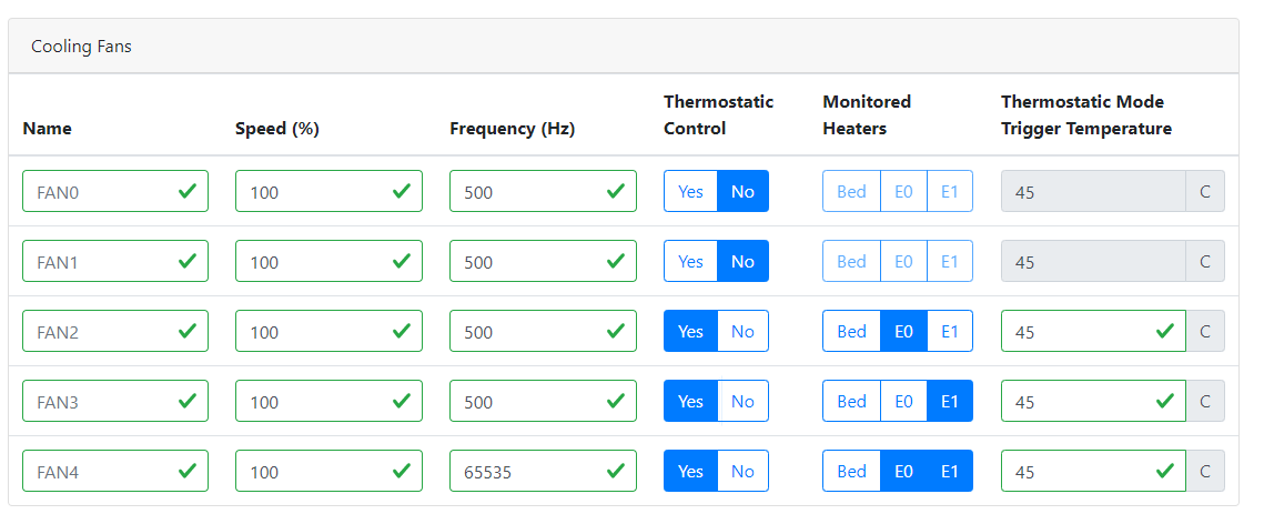
; Fans
M950 F0 C"out7" Q500 ; create fan 0 on pin out7 and set its frequency
M106 P0 S1 H-1 ; set fan 0 value. Thermostatic control is turned off
M950 F1 C"out8" Q500 ; create fan 1 on pin out8 and set its frequency
M106 P1 S1 H-1 ; set fan 1 value. Thermostatic control is turned off
M950 F2 C"out4" Q500 ; create fan 2 on pin out4 and set its frequency
M106 P2 S1 H1 T45 ; set fan 2 value. Thermostatic control is turned on
M950 F3 C"out5" Q500 ; create fan 3 on pin out5 and set its frequency
M106 P3 S1 H2 T45 ; set fan 3 value. Thermostatic control is turned on
M950 F4 C"out9" Q65535 ; create fan 4 on pin out9 and set its frequency
M106 P4 S1 H1:2 T45 ; set fan 4 value. Thermostatic control is turned on
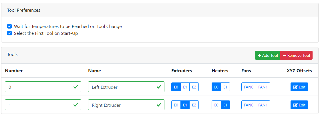
; Tools
M563 P0 S"Left Extruder" D0 H1 F0 ; define tool 0
G10 P0 X0 Y0 Z0 ; set tool 0 axis offsets
G10 P0 R0 S0 ; set initial tool 0 active and standby temperatures to 0C
M563 P1 S"Right Extruder" D1 H2 F1 ; define tool 1
G10 P1 X0 Y0 Z0 ; set tool 1 axis offsets
G10 P1 R0 S0 ; set initial tool 1 active and standby temperatures to 0C
; Custom settings
M584 X0 Y1 Z2:3 E4:5 ; Driver 0 controls the X motor, 1 controls Y, 2 and 3 control Z motors, 4 and 5 control E motors
M671 X-35:335 Y100:100 ; Define positions of Z Axis lead screws
M307 H0 A233.6 C1178.2 D0.5 V24.1 B0 ; Heated Bed Calibration 26/10/20
M307 H1 A327.8 C161.2 D2.8 V24.2 B0 ; Left Extruder Heater Calibration 17/10/20
M307 H2 A325.8 C160.8 D3.4 V24.2 B0 ; Right Extruder Heater Calibration 17/10/20
M106 P0 S0 ; Turn Fan 0 OFF
M106 P1 S0 ; Turn Fan 1 OFF
; Miscellaneous
M575 P1 S1 B57600 ; enable support for PanelDue
T0 ; select first tool
And bed.g (for completeness, no actual issues)
; bed.g
; called to perform automatic bed compensation via G32
;
; Setup for bed levelling using multiple independent Z motors

G28 ; Home
G30 P0 X0   Y100 Z-99999    ; Z probe Left side lead screw
G30 P1 X255 Y100 Z-99999 S2 ; Z probe Right side lead screw


;M561 ; clear any bed transform
;G29  ; probe the bed and enable compensation
Finally my code, with the main change tidying up around the M584 area to reflect the extra Z drive, I've modified the lines below it to reflect the shuffling around.
; Configuration file for Duet 3 (firmware version 3)
; executed by the firmware on start-up
;
; BigBox Dual - Z and Extruders

; General preferences
G90                                                    ; send absolute coordinates...
M83                                                    ; ...but relative extruder moves
M550 P"Duet 3"                                         ; set printer name

; Drives
M569 P0.0 S1                                           ; physical drive 0.0 goes forwards
M569 P0.1 S0                                           ; physical drive 0.1 goes backwards
M569 P0.2 S0                                           ; physical drive 0.2 goes backwards
M569 P0.3 S0                                           ; physical drive 0.3 goes backwards
M569 P0.4 S1                                           ; physical drive 0.4 goes forwards
M569 P0.5 S0                                           ; physical drive 0.5 goes backwards
M584 X0.0 Y0.1 Z0.2:0.3 E0.4:0.5                       ; set drive mapping X,Y,Z0,Z1,E0,E1
M350 X16 Y16 Z16:16 E16:16 I1                          ; configure microstepping with interpolation
M92 X160.00 Y360.00 Z800.00:800.00 E304.00:304.00      ; set steps per mm
M566 X900.00 Y900.00 Z60.00:60.00 E120.00:120.00       ; set maximum instantaneous speed changes (mm/min)
M203 X9000.00 Y9000.00 Z600.00:600.00 E4500.00:4500.00 ; set maximum speeds (mm/min)
M201 X800.00 Y800.00 Z20.00:20.00 E1000.00:1000.00     ; set accelerations (mm/s^2)
M906 X1360 Y1600 Z1344:1344 E1360:1360 I30             ; set motor currents (mA) and motor idle factor in per cent
M84 S30                                                ; Set idle timeout

; Axis Limits
M208 X0 Y0 Z0 S1                                       ; set axis minima
M208 X260 Y240 Z280 S0                                 ; set axis maxima

; Endstops
M574 X1 S1 P"io1.in"                                   ; configure active-high endstop for low end on X via pin io1.in
M574 Y1 S1 P"io2.in"                                   ; configure active-high endstop for low end on Y via pin io2.in
M574 Z1 S2                                             ; configure Z-probe endstop for low end on Z

; Z-Probe
M558 P1 C"io3.in" H5 F120 T6000                        ; set Z probe type to unmodulated and the dive height + speeds
G31 P500 X0 Y0 Z1.888                                  ; set Z probe trigger value, offset and trigger height
M557 X0:240 Y0:160 S40                                 ; define mesh grid

; Heaters
M308 S0 P"temp0" Y"thermistor" T100000 B4267           ; configure sensor 0 as thermistor on pin temp0
M950 H0 C"out0" T0                                     ; create bed heater output on out0 and map it to sensor 0
M307 H0 B0 S1.00                                       ; disable bang-bang mode for the bed heater and set PWM limit
M140 H0                                                ; map heated bed to heater 0
M143 H0 S120                                           ; set temperature limit for heater 0 to 120C
M308 S1 P"spi.cs0" Y"rtd-max31865"                     ; configure sensor 1 as thermocouple via CS pin spi.cs0
M950 H1 C"out1" T1                                     ; create nozzle heater output on out1 and map it to sensor 1
M307 H1 B0 S1.00                                       ; disable bang-bang mode for heater  and set PWM limit
M308 S2 P"spi.cs1" Y"rtd-max31865"                     ; configure sensor 2 as thermocouple via CS pin spi.cs1
M950 H2 C"out2" T2                                     ; create nozzle heater output on out2 and map it to sensor 2
M307 H2 B0 S1.00                                       ; disable bang-bang mode for heater  and set PWM limit

; Fans
M950 F0 C"out7" Q500                                   ; create fan 0 on pin out7 and set its frequency
M106 P0 S1 H-1                                         ; set fan 0 value. Thermostatic control is turned off
M950 F1 C"out8" Q500                                   ; create fan 1 on pin out8 and set its frequency
M106 P1 S1 H-1                                         ; set fan 1 value. Thermostatic control is turned off
M950 F2 C"out4" Q500                                   ; create fan 2 on pin out4 and set its frequency
M106 P2 S1 H1 T45                                      ; set fan 2 value. Thermostatic control is turned on
M950 F3 C"out5" Q500                                   ; create fan 3 on pin out5 and set its frequency
M106 P3 S1 H2 T45                                      ; set fan 3 value. Thermostatic control is turned on
M950 F4 C"out9" Q65535                                 ; create fan 4 on pin out9 and set its frequency
M106 P4 S1 H1:2 T45                                    ; set fan 4 value. Thermostatic control is turned on

; Tools
M563 P0 S"Left Extruder" D0 H1 F0                      ; define tool 0
G10 P0 X0 Y0 Z0                                        ; set tool 0 axis offsets
G10 P0 R0 S0                                           ; set initial tool 0 active and standby temperatures to 0C
M563 P1 S"Right Extruder" D1 H2 F1                     ; define tool 1
G10 P1 X0 Y0 Z0                                        ; set tool 1 axis offsets
G10 P1 R0 S0                                           ; set initial tool 1 active and standby temperatures to 0C

; Custom settings

M671 X-35:335 Y100:100                                 ; Define positions of Z Axis lead screws

M307 H0 A233.6 C1178.2 D0.5 V24.1 B0                   ; Heated Bed Calibration 26/10/20
M307 H1 A327.8 C161.2 D2.8 V24.2 B0                    ; Left Extruder Heater Calibration 17/10/20
M307 H2 A325.8 C160.8 D3.4 V24.2 B0                    ; Right Extruder Heater Calibration 17/10/20

M106 P0 S0                                             ; Turn Fan 0 OFF
M106 P1 S0                                             ; Turn Fan 1 OFF

; Miscellaneous
M575 P1 S1 B57600                                      ; enable support for PanelDue
T0                                                     ; select first tool
When I install my config.g I get 3 warinings:-

The (M55) hostname, I'm not sure about as I've never changed it from the default.
The M350 seems to be the issue but I'm not sure why? I've checked the RepRap G-Code and it looks correct. I've tried using my M584 declaration without the 0. before the drives (as per custom setting), unfortunately to no avail.
The (M307) heater seating is from the PID's calculated during the calibration of heated plate.
I'm inclined just to carry on with what I have but have the curse of the Engineer in just knowing what I've done wrong / missed.
")