@puterpro said in Can't change current for new stepper:
M906 X1000.00 Y1000 Z700 E1000 U700.00 I30
I doubt this would be the problem but is it OK to put non integer numbers here? maybe delete the 2 ".00".
@puterpro said in Can't change current for new stepper:
M906 X1000.00 Y1000 Z700 E1000 U700.00 I30
I doubt this would be the problem but is it OK to put non integer numbers here? maybe delete the 2 ".00".
@phaedrux Because the limit for the maestro is 28V and the factory motors are high inductance, to the point that the chopper frequency is still in the audible range even at the max voltage.
I measured my Z motors on my CR-10s:
Resistance: 9.6Ohm
Inductance: 7.6mHy@1kHz (frequency used in datasheets)
Since I was keeping my 12V PSU for the bed (I haven't checked if it can be wired for 24V, but it has 4 pads) I only supply 27.4V to the board and everything else is 12V powered (at 27.5-.6V the maestro doesn't let you move the steppers).
edit: let us know how the swap works out, I would love to be able to use spreadcycle in silence.
@vacalos regular UTP, ethernet cable, it would probably be best to cut one of the short ones made to connect to the devices because as far as I know they are made with stranded wire, so it's more flexible. I don't know how durable they are in a constantly moving printer.
I'm also interested, I am pretty fast at making the measurements and I like the results and the graphs but it takes a while to make them manually, I would love to have them automated or at least not manual.
@aimrabbit No, they just lower the voltage to be measured by the microcontroller. if you get 24v in DWC(Web) of M122 without the PanelDue connected then there is no need to do what I told you.
@magnusjen Interesting I would like to see what @dc42 has to say about it, but if I am not mistaken that doesn't look good at all.
Perhaps you could measure the voltage in the following points, one (or both) are used to measure Vin and you should see close to Vin/11.
The pictures may not match your board exactly.
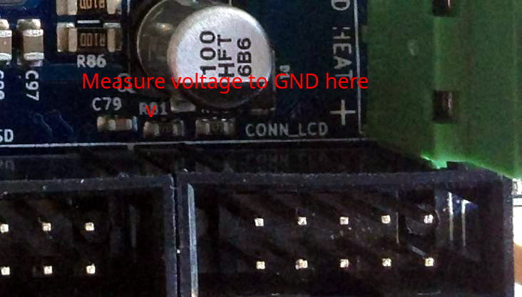
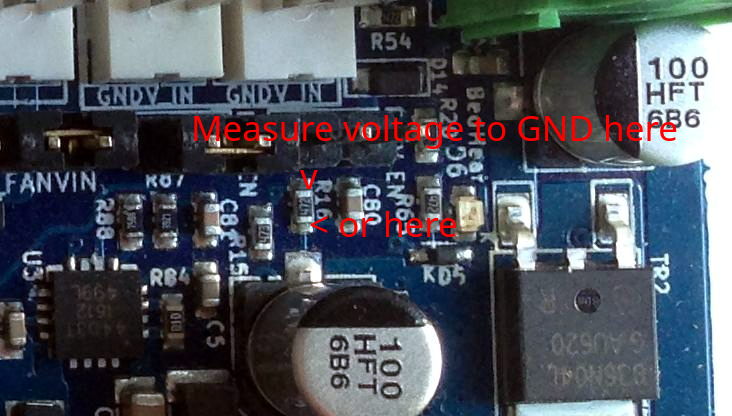
I don't know which side is GND.
You could measure Resistors 80,81 or 15,16 (I'm not sure which pair is used to measure) that are near the always on fans connectors and 5vEnable jumper on the side of the expansion header. There should be 2 of 4.7kOhm and 2 of 47kOhm.
Although as far as I know (could be wrong) not many things are affected considerably by having a wrong input voltage reading (power loss range, heater power voltage compensation,etc) so I wouldn't consider it a big deal, but if it is a resistor it would be easy to fix.
edit: added pictures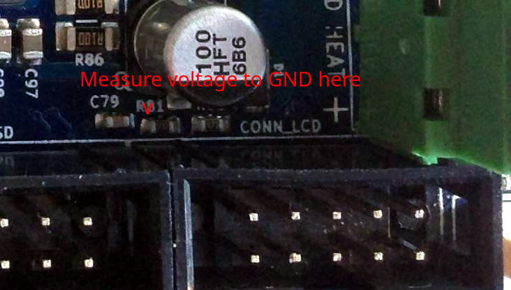
you should see Vin/11 more of less.
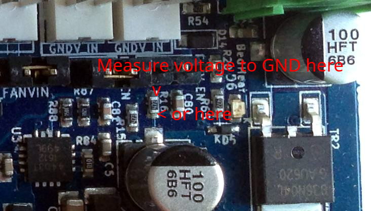
same here, I don't know which side is GND so you will see 0 in one of the points.
edit2: I took the pictures from the internet so they may not match your board exactly, but it should be similar.
since 12.3/8.5 = 1.44 and 24/16.5 = 1.45 are the same ratio, it is possible that there is something wrong with the resistors of the divider that measures Vin.
I installed a maestro in my cr-10, the only problem is that due to the relatively high inductance of the motors mine came with, it's noisy in spreadcycle, not a problem with duet wifi/ethernet.
As far as I remember the only weird thing during install was that the 12864 screen has the notch backwards, so check the pinout if you are not using a paneldue, again not a problem with wifi/ethernet.
You can use the Mosfet board without problems, since you are opening it, you could add Thermal paste to the Mosfet, mine came without it.
Edit: there is an adapter in thingiverse to mount the board inside the stock control box, it's not perfect, but it works.
@briskspirit I disabled Temperature Control from the addon "printer settings" in the cura "marketplace".
Inside each Filament Config Macro:
M350 E16 I1		;Back to 16 microstepping to set it.
;NonLinear Extrusion
M92 E433.5 ;Adjusted for optimal curve fitting
M592 D0 A-0.00051 B0.00061 ;Nonlinear Extrusion parameters
M221 S101		;Flow(Diameter Compensation)
;Restore Microstepping to its value
M98 P0:/Macros/MotorControl/SetExtruderMicrostepping.g

;Set Temperatures
M140 S60			; Set Bed Temperature
G10 P0 R140 S215		; Set Nozzle Active and Standby Temperature
In this case FW Retraction (Pressure Advance also) is not configured because its the same as the one in the General Config file for PLA. And you can ignore the microstepping part, it's there so I can change the microstepping without editing all the Filaments config Files.
The Slicer start G-code calls a PrePrint macro:
M703		; Load Filament specific config, including Temps
T100 P0		; Sets T0 to Standby Temperature, after the T0 issued by the Slicer

M116 H0		; Wait for Bed Temperature to be reached
T0 P0		; Selects Tool 0 (active temp), without executing Tool-change Macros
G28
G29 S1		; Load Grid Compensation
G0 X320		 ; Move X to ooze Land
M116		; Wait for All Heaters

M98 P0:/Macros/Priming/PrimeOnBed.g
I am using it to set Nozzle and bed temperatures, Extruder steps/mm, filament Flow/Diameter, Retraction and Non-linear Extrusion, so I have a config per roll that gets updated when initial calibrations are performed.
Since I didn't like the flexibility of cura materials (at least from a while ago) now I manage all material parameters with config Files in the Duet.
Found a typo, probably too late.
Page 10 in the book or 18 in the "table of contents - foreword" pdf it says open-ource, instead of open-source, I guess.
Edit:I don't know if it is in the final version.
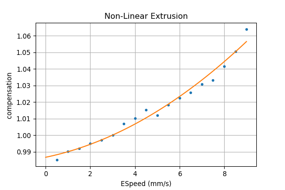
I would like this feature too, measuring extrusion at different speeds for non-linear extrusion takes most of my tuning time.
I added M703 to the start macro that is called in the start gcode.
I believe there is room for improvement by loading the config automatically but this works.
@patrickwjoyce
That motor has a high inductance, switching to 24v will increase the chopping frequency, I'm not sure if 24v is enough to take it above the audible range.
I have motors with 8mH @1khz (datasheets test frequency) inductance and at 12v the chopper frequency is around 10khz. Not sure if the scaling is linear, when I install my 24v supply will see.
I can use them in stealthchop only at high speeds (200mm/s without bearing noises) , you have to reduce the max Acceleration a bit.
@wilriker Thanks, didn't realize that.
@phaedrux You could be right, but since the seller has already agreed to send me a new one.... I'll test it in mid air when the new one arrives (couple of months). Worst case I end up with 2 working probes.
I assumed it was designed to be in close proximity to ferrous materials and put it in the only place with free space that doesn't limit movement length, could have been a bad choice, will see after testing.