Duet3D Logo Duet3D
    • Tags
    • Documentation
    • Order
    • Register
    • Login
    1. Home
    2. jallen810
    3. Posts
    • Profile
    • Following 1
    • Followers 0
    • Topics 14
    • Posts 109
    • Best 5
    • Controversial 0
    • Groups 0

    Posts made by jallen810

    • RE: InputShaping-Plugin-0.1.0-rc7 released (repacked)

      @fred-y @mfs12 I have to say, after using Klipper's system to "Autotune" this is bit archaic by comparison. I sure hope this will be continued to be improved upon as i think it has merit. WIthout having a huge understanding of the algorithms involved here let me take a stab at how i think your system could be improved to help the user make educated decisions on I.S. for their system.

      1.) The Analysis graphing always defaults to displaying all 3 (X,Y,Z) axes simulataneously. This is overwhelming, the configuration dialog asks us to pick 1 axes to test, thus the accelerometer readings should only be recorded for this axis (or filtered after the fact) so as to not confuse the user.

      2.) I have notice that my acclerometer testing file names are not being generate with the user selected (I.S. algo type, Frequency, Damping, axis desire, etc..) they simply get some random numbers & a date/time stamp... (Pic below)

      Supposed to name:
      SupposedName.png

      Actual Name i get when CSV is saved:
      ActualName.png

      So i have to go one-by-one, test, record, rename, update settings, repeat... very slow & frustrating simply to get my filenames correct so i can compare them....

      3.) The analysis doesn't make any kind of recommendations for solving any of our variables.... The user must optimize 3-variables... not likely going to happen in any sort of quick situation. My recommendation would be for the system to take a standing still reading to account for environmental resonances (fans/etc...) and ignore these values when analyzing the accelerometer data. From there it should test increasing frequencies (Defined by user OR 0-150Hz F.E.) and then run that through solving for each I.S. type one-by-one to determine optimal frequency to cancel and maximum accel/decel & dampening at solved frequency...
      This would, in effect, do exactly what Klipper I.S. does so well (and in mere minutes) but would give us a graphical representation of it simultaneously....

      I truly hope you keep at it and make some improvements to the system, I don't want this to sound like negative because this is great work so far, it just simply isn't complete yet, if you mission is to provide the user with "turnkey" information to improve their prints. I will keep playing with this and upgrading as beta's come out.

      posted in Plugins for DWC and DSF
      jallen810undefined
      jallen810
    • RE: Error: This kinematics does not support auto-calibration

      @phaedrux said in Error: This kinematics does not support auto-calibration:

      Basically. The feature was deprecated in favour of something better. To approximate the old style you can just define a sparse grid with 4 or 9 points, ie a 2x2 or 3x3

      Okay fair enough. I was able to make this work with a G29 4-corners probe.
      M557 like this:
      M557 X3:353 Y5:354 P2:2

      Lastly I edited my bed.g to run a G29 S0 & S1 instead of the series of G1/G30 commands i had before, then I put the same G29 S0 & S1in my Start Gcode.

      Thanks for your help.

      posted in Firmware installation
      jallen810undefined
      jallen810
    • RE: Error: This kinematics does not support auto-calibration

      @phaedrux Okay i was wondering about that...
      Follow up question i have is, why did it work on RRF1.18.1?? Just because Mesh Comp didn't exist back then?

      posted in Firmware installation
      jallen810undefined
      jallen810
    • Error: This kinematics does not support auto-calibration

      TIA for the help here.
      I am trying to upgrade my work printer (F410 by Fusion3D) from RRF1.18 up to current. I am running RRF3.3 pretty well but i've notice my Z offsets (set in G31 line) are not being used. The issue is the nozzle is too close to the bed.
      I've dug into my bed.g and found that the old firmware was using M667 S1 and i see that is now deprecated to M669 K1. I updated but when my machine runs the bed.g it still won't accept the 4 probed points... about to tear my hair out. Any advice would appreciated.

      Printer Specs worth mentioning:
      -Capacitive nozzle probe which touches 4 tinfoiled corners on the glass bed
      -Bed homes Z at bottom (which is max Z position)
      -Bed is powered by 1x Z motor that is belted to 3 lead screws with manual adjustment screws on the plate itself (aka not able to tram a bed like Railcore/RatRig/Voron) it just moves the whole bed up/down in time with the XY movement.

      I'm attaching the "OEM" Firmware and the New Firmware for comparisons...
      RRF3.3 Config-Override.g
      RRF3.3 Bed.g
      RRF 3.3 Config.g

      bed - F410 RRF1.18.1.g
      config-override - F410 RRF1.18.1.g
      config - F410 RRF1.18.1.g

      posted in Firmware installation
      jallen810undefined
      jallen810
    • RE: Duet 3 Mini 5+ : Initial announcement

      @dc42 ah okay fair enough! I’m by no means an OEM. They need them due development for sure.

      posted in General Discussion
      jallen810undefined
      jallen810
    • RE: Duet 3 Mini 5+ : Initial announcement

      @dc42 said in Duet 3 Mini 5+ : Initial announcement:

      We have a small number of generation 1 prototypes a

      What's the price on them?

      posted in General Discussion
      jallen810undefined
      jallen810
    • RE: Duet 3 Mini 5+ : Initial announcement

      @dc42 Is it possible to get my hands on a Duet3 Mini now and help with testing or is that closed?

      posted in General Discussion
      jallen810undefined
      jallen810
    • RE: Pinda 2 probe with temperature compensation

      @dc42 said in Pinda 2 probe with temperature compensation:

      . So if you have a spare thermistor input, you can connect the PINDA thermistor to that.

      @dc42 if i just ziptied a spare thermistor to my existing probe could it do the same? Without a PINDA? that way i had the separate ground?
      And forgive my ignorance on RRF3.0 still getting used to it,
      do i just make an M950/M160 for this new thermistor and assign it to a "ghost" heater?

      posted in Duet Hardware and wiring
      jallen810undefined
      jallen810
    • RE: Pinda 2 probe with temperature compensation

      @Argo @Phaedrux did y’all ever figure this out how utilize this? I feel like I read somewhere that @dc42 was going to work the PINDA2 compensation into the next firmware release, has that happened with 3.1?
      I want to give this a shot to help with the excessive warping I experience in my heated chamber.

      posted in Duet Hardware and wiring
      jallen810undefined
      jallen810
    • RE: Possible PWM port issue & RRF3 Question

      @Phaedrux @bearer @droftarts all very good links, i think that clears up the concept for me so i understand what i did wrong. I will investigate and test everything this weekend. I'm happy this re-wire is finally complete. I can finally get back to printing 😉

      posted in Duet Hardware and wiring
      jallen810undefined
      jallen810
    • RE: Possible PWM port issue & RRF3 Question

      @Phaedrux here is how my bed is oriented, mind you, the code i placed above works as this diagram shows, it just doesn't make sense that is it not exactly the same as my RRF2.x was. It would seem that should not change from one to the next.
      [Lastly, note i need to update my M557, i just noticed a typo when i was making this diagram 😃 ]

      7c134f70-bc18-4b77-a9aa-14e2f12724e8-image.png

      posted in Duet Hardware and wiring
      jallen810undefined
      jallen810
    • RE: Possible PWM port issue & RRF3 Question

      @droftarts @Phaedrux @bearer
      Thank you all for your help with this upgrade to RRF3, I did finally get everything working properly again! I am running my first print now! Woot woot!

      One last question to you @droftarts, I figured out that I had to invert my endstop signals ~2hr before your comment but I had to do the following:

      CONFIG.g

      ;----Endstops--------------------------------------------------------------------------------------------------------------------------------------------------------------------------
      M574 X1 S1 P"!xstop"                                       ; configure active-low endstop for low end on X via pin xstop
      M574 Y1 S1 P"!ystop"                                       ; configure active-low endstop for low end on Y via pin ystop
      M574 Z1 S2                                                 ; configure Z-probe endstop for low end on Z


      HOMEX.g

      ; homex.g
      ; called to home the X axis
      ;
      ; generated by RepRapFirmware Configuration Tool v3.1.4 on Sat Aug 15 2020 15:29:15 GMT-0400 (EDT)
      G91              ; relative positioning
      G1 H2 Z5 F6000   ; lift Z relative to current position
      G1 H1 X-305 F1800 ; move quickly to X axis endstop and stop there (first pass) 305
      G1 H2 X5 F6000  ; go back a few mm
      G1 H1 X-305 F360  ; move slowly to X axis endstop once more (second pass)
      G1 H2 Z-5 F6000  ; lower Z again
      G90              ; absolute positioning
      

      HOMEY.g

      ; homey.g
      ; called to home the Y axis
      ;
      ; generated by RepRapFirmware Configuration Tool v3.1.4 on Sat Aug 15 2020 15:29:15 GMT-0400 (EDT)
      G91              ; relative positioning
      G1 H2 Z5 F6000   ; lift Z relative to current position
      G1 H1 Y-340 F1800 ; move quickly to Y axis endstop and stop there (first pass)
      G1 H2 Y-5 F6000  ; go back a few mm
      G1 H1 Y-340 F360  ; move slowly to Y axis endstop once more (second pass)
      G1 H2 Z-5 F6000  ; lower Z again
      G90              ; absolute positioning
      

      Question is: Why did I have to switch my "home" coordinate for both X&Y from 305/340 to -305/-340 when I switched to RRF?

      posted in Duet Hardware and wiring
      jallen810undefined
      jallen810
    • RE: Possible PWM port issue & RRF3 Question

      @Phaedrux okay I will try that, what exactly is the application for this pull up resistor? Could it be the reason my endstops are acting funny?
      It almost acts like the machine thinks it’s homes as soon as I push the home button... very weird.

      My homex,y,z and all fills are updated from S to H.. so that looks fine... any other ideas other than I just need to try running 24v of power to them?

      posted in Duet Hardware and wiring
      jallen810undefined
      jallen810
    • RE: Possible PWM port issue & RRF3 Question

      @Phaedrux i tested the TR8 mosfet for E1 and i only get 4.5v out of it. my guess it was also blown. @bearer is helping setup external mosfets to control my fans via the 50pin expansion header. I think i am set there.

      I played with the probe settings after noticing the same things u just mentioned.
      I tried both probe types 1 & 5, I tried inverting the signal with a "!" in front of the C var, i tried changing the end stops for XYZ from 0, 1, 2.
      Nothing works, the only thing i notice is the probe reading is 1000 for P1 and 983 for P5 when no metal is present (probe light off). When i put a metal object under it, the reading drops to ~20.
      It acts this way for every permutation of the above code changes.
      I know this, my optical sensors were wired in RRF2 to the same pin as they are now, just ~1m extra wire in between. These sensors have to run 5v+, not 3.3v per the way the OEM wired them. But if i download the sensor Mfgr's data sheet it says, it needs 12-24v in. GL_8H Sidewinder X1 Endstops Data Sheet.pdf

      Do you suppose the extra length of wire causes enough resistance that the 5v that previously worked, now is not sufficient? If so, i could re-wire to pull off the main's power in... just a lot of extra work that i may not need to do...

      posted in Duet Hardware and wiring
      jallen810undefined
      jallen810
    • RE: Duet 3 Mini 5+ : Initial announcement

      This looks awesome! I am especially interested in being able to use my 24v PS and then use 12v fans as they're so much easier to get ahold of!
      Was the rumor I heard that Duet3 Mini will have both Ethernet and WiFi, true as well?

      posted in General Discussion
      jallen810undefined
      jallen810
    • RE: Possible PWM port issue & RRF3 Question

      @Phaedrux so I talked with @bearer and he explained this and we tested my wiring across E1vin and mains negative. Fan worked, wiring correct.

      1.) Then I hooked up fan negative to E1negative and changed the config line u said above.
      Powered up and nothing, using fan control on both DWC and PanelDue are non responsive. my E1 LED is not lighting up. It’s almost like we forgot to associate something? Ideas?

      2.) Also, we’re you able to see anything in the config I posted that would suggest why my probe isn’t working and why my homing isn’t working?
      3.) Lastly, I’ve tested X,Y,Z movement. Y & Z work as expected. But X only moves in the negative direction (left as it is configured currently) it does not respond when asked to move +x. Does this mean I swapped one of my stepper wire pairs? How do i identify and test that without blowing something up?

      posted in Duet Hardware and wiring
      jallen810undefined
      jallen810
    • RE: Possible PWM port issue & RRF3 Question

      @bearer okay so @Phaedrux said I can tag into the E1 heater for the 24v and then pick a heater pin on the expansion slot. My question is how do I actually physically wire this thing up?

      Red wire [from fan +V] ---> Heater4 (pin13)
      Black wire [from fan -V] ----> E1+24v

      Like this:
      Duet2WiFi Pinout 2.JPG

      posted in Duet Hardware and wiring
      jallen810undefined
      jallen810
    • RE: Possible PWM port issue & RRF3 Question

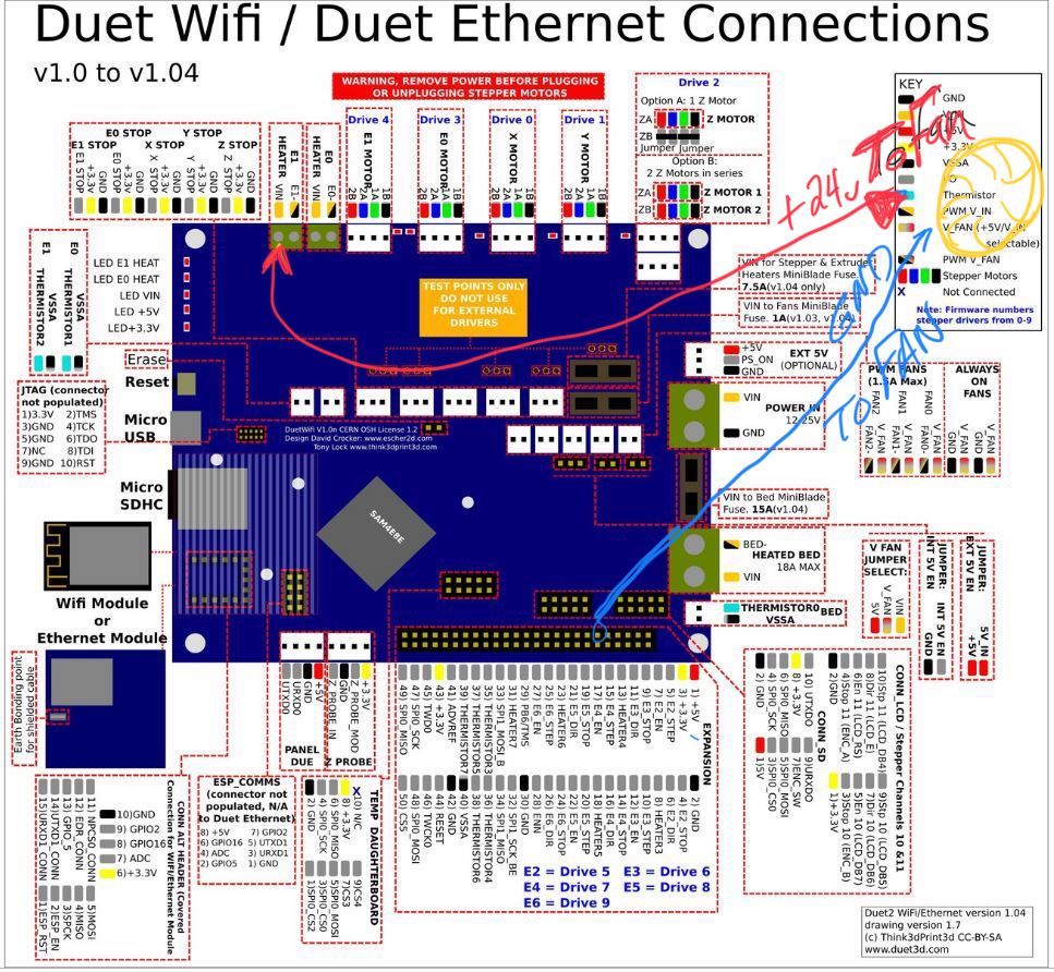
      @Phaedrux I had a blonde moment, I can't use a normal 2pin fan can I?
      I need a 3+ wire fan right? (sorry never actually used PWM function of fans before)

      My artillery sidewinder specs:

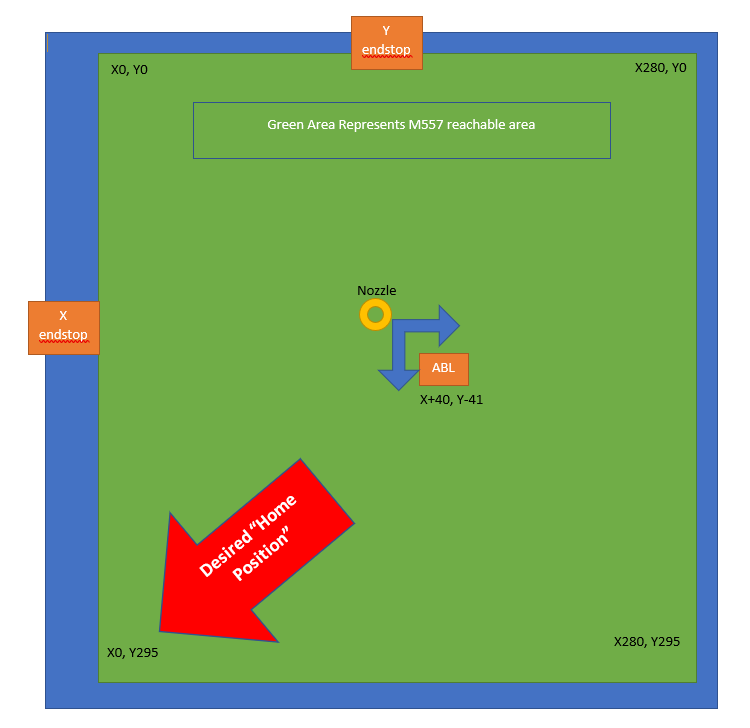
      Xaxis: homes at 0, left side (Panasonic GL8H optical NPN NC sensor)
      Yaxis: homes at back, but 0 is actually at the front (Panasonic GL8H optical NPN NC sensor)
      Z = Inductive ABL probe (Panasonic GXHL15A NPN NC sensor)

      Lastly, here is my RRFconfigurator custom config.g for RRF3.1:

      ; Configuration file for Duet WiFi (firmware version 3)
      ; executed by the firmware on start-up
      ;
      ; generated by RepRapFirmware Configuration Tool v3.1.4 on Sat Aug 15 2020 15:29:14 GMT-0400 (EDT)
      
      ; General preferences
      G90                                                       ; send absolute coordinates...
      M83                                                       ; ...but relative extruder moves
      M550 P"Sidewinder X1 RRF3"                                ; set printer name
      
      ; Network
      M552 S0
      M552 S1 P192.168.1.50				   ; Assign fixed IP address
      M553 P255.255.255.0				   ; Assign Netmask to match my network
      M554 P192.168.1.1				   ; Assign Gateway IP address to match network
      M552 S1                                                   ; enable network
      M586 P0 S1                                                ; enable HTTP
      M586 P1 S0                                                ; disable FTP
      M586 P2 S0                                                ; disable Telnet
      
      ; Drives
      M569 P0 S1                                                ; physical drive 0 goes forwards
      M569 P1 S0                                                ; physical drive 1 goes backwards
      M569 P2 S0                                                ; physical drive 2 goes backwards
      M569 P3 S0                                                ; physical drive 3 goes backwards
      M584 X0 Y1 Z2 E3                                          ; set drive mapping
      M350 X16 Y16 Z16 E16 I1                                   ; configure microstepping with interpolation
      M92 X80.00 Y80.00 Z400.00 E415.00                         ; set steps per mm
      M566 X900.00 Y900.00 Z60.00 E1200.00                      ; set maximum instantaneous speed changes (mm/min)
      M203 X9000.00 Y9000.00 Z1500.00 E3000.00                  ; set maximum speeds (mm/min)
      M201 X500.00 Y500.00 Z20.00 E166.67                       ; set accelerations (mm/s^2)
      M906 X800 Y800 Z800 E800 I30                              ; set motor currents (mA) and motor idle factor in per cent
      M84 S30                                                   ; Set idle timeout
      
      ; Axis Limits
      M208 X0 Y0 Z0 S1                                          ; set axis minima
      M208 X300 Y340 Z400 S0                                    ; set axis maxima
      
      ; Endstops
      M574 X2 S1 P"xstop"                                       ; configure active-high endstop for high end on X via pin xstop
      M574 Y2 S1 P"ystop"                                       ; configure active-high endstop for high end on Y via pin ystop
      M574 Z2 S2                                                ; configure Z-probe endstop for high end on Z
      
      ; Z-Probe
      M558 P1 C"zprobe.in" H5 F600 T6000                        ; set Z probe type to unmodulated and the dive height + speeds
      G31 P1000 X40 Y-41 Z2.5                                   ; set Z probe trigger value, offset and trigger height
      M557 X45:295 Y10:280 S40                                  ; define mesh grid
      
      ; Heaters
      M308 S0 P"bedtemp" Y"thermistor" T100000 B4138            ; configure sensor 0 as thermistor on pin bedtemp
      M950 H0 C"bedheat" T0                                     ; create bed heater output on bedheat and map it to sensor 0
      M307 H0 B1 S1.00                                          ; enable bang-bang mode for the bed heater and set PWM limit
      M140 H0                                                   ; map heated bed to heater 0
      M143 H0 S130                                              ; set temperature limit for heater 0 to 130C
      M308 S1 P"e0temp" Y"thermistor" T500000 B4723 C1.19622e-7 ; configure sensor 1 as thermistor on pin e0temp
      M950 H1 C"e0heat" T1                                      ; create nozzle heater output on e0heat and map it to sensor 1
      M307 H1 B0 S1.00                                          ; disable bang-bang mode for heater  and set PWM limit
      
      ; Fans
      M950 F0 C"fan0" Q500                                      ; create fan 0 on pin fan0 and set its frequency
      M106 P0 C"Layer Fan 1" S0 H-1                             ; set fan 0 name and value. Thermostatic control is turned off
      M950 F1 C"fan1" Q500                                      ; create fan 1 on pin fan1 and set its frequency
      M106 P1 C"HE Fan 2" S1 H1 T45                             ; set fan 1 name and value. Thermostatic control is turned on
      
      ; Tools
      M563 P0 D0 H1 F0                                          ; define tool 0
      G10 P0 X0 Y0 Z0                                           ; set tool 0 axis offsets
      G10 P0 R0 S0                                              ; set initial tool 0 active and standby temperatures to 0C
      
      ; Custom settings are not defined
      
      ; Miscellaneous
      M575 P1 S1 B57600                                         ; enable support for PanelDue
      M501                                                      ; load saved parameters from non-volatile memory
      M911 S10 R11 P"M913 X0 Y0 G91 M83 G1 Z3 E-5 F1000"        ; set voltage thresholds and actions to run on power loss


      and for reference, here is the back up of the RRF2.03. config.g that I made just before updating to RRF3 this afternoon:

      ; Configuration file for Duet WiFi (firmware version 2.03)
      ; executed by the firmware on start-up
      ;
      ; generated by RepRapFirmware Configuration Tool v2.1.8 on Sat Apr 11 2020 14:47:32 GMT-0400 (Eastern Daylight Time)
      ; Revised by Jake Allen on 4.18.2020 @ 10:30am EST
      
      ;-----General preferences-----------------------------------------------------------------------------------------------------------------
      G90                                                ; send absolute coordinates...
      M83                                                ; ...but relative extruder moves
      M550 P"Sidewinder X1"                              ; set printer name
      
      ;-----Network----------------------------------------------------------------------------------------------------------------------------
      M552 S0
      ;M552 S1 P192.168.1.50				   ; Assign fixed IP address
      M553 P255.255.255.0				   ; Assign Netmask to match my network
      M554 P192.168.1.1				   ; Assign Gateway IP address to match network
      M552 S1           	               		   ; enable network
      M586 P0 S1                                         ; enable HTTP
      M586 P1 S0                                         ; disable FTP
      M586 P2 S0                                         ; disable Telnet
      
      ;-----Drives-----------------------------------------------------------------------------------------------------------------------------
      M569 P0 S0 D2                                	   ; (X-Axis) drive 0 goes forwards (Jake wrong config M569 P0 S1)
      M569 P1 S1 D2	 	                           ; (Y-Axis) drive 1 goes forwards 
      M569 P2 S1 D2                                      ; (Z-Axis) drive 2 goes forwards
      M569 P3 S1 D2                                      ; (Extruder) drive 3 goes backward with Bondtech (titan = S0, Bondtech = S1)
      M584 X0 Y1 Z2 E3                                   ; set drive mapping
      M350 X16 Y16 Z16 E16 I1                            ; configure micro-stepping with interpolation
      M92 X80.12 Y80.12 Z399.78 E415.0                   ; set steps per mm (from Jake's Marlin Setup) (titan=446mm)
      M566 X800.00 Y980.00 Z60.00 E2500.00               ; set maximum instantaneous speed changes (mm/min) --> E180 to E2500, Z12 to Z60
      M203 X9000.00 Y9000.00 Z1500.00 E3000.00           ; set maximum speeds (mm/min) --> X&Y from 6000 (100mm/s) to 9000 (150mm/s)
      M201 X800.00 Y800.00 Z400.00 E10000.00               ; set accelerations (mm/s^2) E10000
      M906 X800 Y800 Z800 E800 I30                       ; set motor currents (mA) and motor idle factor in per cent
      M84 S30                                            ; Set idle timeout
      
      ;-----Axis Limits------------------------------------------------------------------------------------------------------------------------
      
      M208 X0 Y0 Z0 S1                                   ; set axis minima
      M208 X300 Y340 Z400 S0                             ; set axis maxima (Changed Y from 300 to 345 to compensate for offset)
      
      ;-----Endstops---------------------------------------------------------------------------------------------------------------------------
      M574 X1 Y1 S0                        		   ; set active low and disabled endstops (To enable Z-endstop add "Z1 or Z2" after y
      M574 Z1 S2                                         ; Define Z to use probe. S2=Home to min
      
      ;-----Z-Probe (BLtouch)------------------------------------------------------------------------------------------------------------------
      
      M307 H3 A-1 C-1 D-1      ; (Duet3d method)  disable Heater7 to free up PWM channel 5 on Duex board for BLTouch
      M558 P5 H5 F600 A1 I1	; GLH8 EndstopABL, Mode P=5, StartProbeH=5mm, Speed=300mm/min, #probes A=3, Invert signal for Endstop I=1 
      ;BLTOUCH; M558 P9 H5 F100 T9000  ; (Duet3D method) P=Select Z-probe mode=9 BLtouch. H=DiveHeight abv bed(mm), F=Speed bed moves, T=TravelSpeed btwn pts 
      
      G31 P25 X40 Y-41 Z1.385	   ; P=Z probe trigger value,X&Y=offset mount relative to nozzle (mm), Z=trigger height 1.84
      
      ;(4020 Mosquito J&L Mount + HL15 Zoff=0.7mm, x=40, y=-41)
      ;(M18 probe,z=1.85mm, x=40, y=-50) 
      ;Stock z-end=0.58					   
      ; Change P500 to P25 and X&Y=0 to X=40 & Y=-38 for probe offset vs. nozzle (3DChanh X58 Y-36)
      
      M557 X45:295 Y10:280 S40                    ; define mesh grid (S20 = 143 points, S45 = 36pts) (Prev: M557 X15:285 Y15:285)
      					   ; Change X0:225 Y45:300 S45 to--> M557 X60:300 Y0:260 S20, S20=156pts, try S24 & S40 =100 & 36pts, Previously S=30
      
      ;-----Heaters----------------------------------------------------------------------------------------------------------------------------
      M140 H0                                            ; remap heated bed to heater 1
      M307 H0 B1 S1.00                                   ; enable bang-bang mode for the bed heater and set PWM limit
      M305 P0 T100000 B4138 R4700                        ; set Bed thermistor + ADC parameters for heater 0
      M143 H0 S125                                       ; set temperature limit for heater 0 to 125C
      ;M305 P1 T100000 B4138 R4700                       ;104GT E3D thermistor set thermistor + ADC parameters for heater 1
      M305 P1 T500000 B4723 C1.196220e-7 H20      	   ; Slice Engr 450°C thermistor Set thermistor +ADC parameters for H1
      M143 H1 S320                                       ; set temperature limit for heater 1 to 300C
      
      ;-----Fans--------------------------------------------------------------------------------------------------------------------------------
      
      M106 P1 S0 H-1 C"Layer_Fan" F500			; Part Cool Layer Fan (8.14.20 blew Mosfets, some cntl Fan1 port so remapped)
      ;M106 P1 S1 H1 T45 C"Heatsink_Fan" F500			; Hotend Heatsink Fan
      ;M106 P2 S0.75 H0 T45 C"BoardCool" F500			; Ducted 4020 DuetBoard Cooling Fan, Bed=45c turn on fan 75%
      
      ;-----Tools-------------------------------------------------------------------------------------------------------------------------------
      M563 P0 S"HOTEND" D0 H1 F1                         ; define tool 0 (8.14.20 change from F0 to F1 bc of blown mosfet remap)
      G10 P0 X0 Y0 Z0                                    ; set tool 0 axis offsets
      G10 P0 R0 S0                                       ; set initial tool 0 active and standby temperatures to 0C
      
      ; Custom settings are not defined
      
      ;-----Miscellaneous-----------------------------------------------------------------------------------------------------------------------
      M501                                               ; load saved parameters from non-volatile memory
      M911 S10 R11 P"M913 X0 Y0 G91 M83 G1 Z3 E-5 F1000" ; set voltage thresholds and actions to run on power loss
      T0                                                 ; select first tool


      posted in Duet Hardware and wiring
      jallen810undefined
      jallen810
    • RE: Possible PWM port issue & RRF3 Question

      @Phaedrux When you tag into E1 heater and Heater 7, just to clarify, I would hook up to E1 to the positive lead to fan. Then I would hook up "13) heater4" (as an example) pin to the negative lead of the fan?

      posted in Duet Hardware and wiring
      jallen810undefined
      jallen810
    • RE: Possible PWM port issue & RRF3 Question

      @Phaedrux that is the RRF Config output! Lol That’s why I was confused. I could have selected the wrong setting somewhere.
      Thanks for the link, I’ll dig in after the kiddos go to bed.

      posted in Duet Hardware and wiring
      jallen810undefined
      jallen810