Hey Guys,
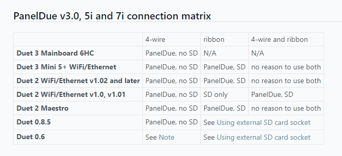
Is there any way to add an external USB Slot or SD Card Slot for GCODE Transfer to the DUET 6 HC.
Thanks for your Help,
Greets
Max
Hey Guys,
Is there any way to add an external USB Slot or SD Card Slot for GCODE Transfer to the DUET 6 HC.
Thanks for your Help,
Greets
Max
@phaedrux yes. That is a possibility as well. But I think that would be to much effort / hardware just to get an Interface and USB-Connectivity.
Greets
Max
Hey guys,
at the moment I am using a PanelDue 7i on my Voron Trident in combination with a Duet 6 HC. Is there any way to make the SD-Card Slot working or add an USB-Stick for file transfer?
Thank you for your help!
Max
@o_lampe yes - thank you for the hint! That's actually what I plant to do: using prusa-slicer / super-slicer for this instead of "firmware-presets".
I reach out to @pfn and ask for his/her progress.
Hey guys,
at the moment I am building a Voron Trident (I think my 4th or 5th Voron printer). When everything is set up I want to install the Enraged Rabbit Mod.
It's a Filament-Changer / Swapper similar to the Prusa MMU or SMuFF.
Is there anyone who already integrated a system like that into the firmware? The mechanics / base setup (2 steppers, 1 servo, filament sensor) are quite simple to get working in RRF3 (I plan to use a Duet 6 HC with a Duet 3HC expanison board for this).
The standard change precdure for filaments is quite easy too using macros and the t#post, t#pre etc. parts of the Firmware.
In the last days I thought about possiblilitys I don't quite yet have solution for:
(1) The Enraged Rabbit Mod uses 2 Filament Sensors - 1 at the "filament changer" 1 at the tool head. I think these could be set up as external triggers with some macros and should work - I also could use the extrnal triggers for the filament change.
(2) Automatic continous printing: If one spool of the filament changer is empty (recognised by filament sensor) swap to the next spool. I think this could be implemented in some way with global variables...but I really do not know how to use them - is there any "good" example? I find the Documentation of GCODE-Meta-Commands is quite lacking in this regard (at least for people with limited programming skils).
Maybe you could provide some input on this!
Thanks
Max
Yes , of course. But after further Investigation I think I miss-read that....the M140 H1:H2 only seems to bei a suggested solution, Not an implemented one in the Firmware yet.
https://forum.duet3d.com/topic/3516/using-multiple-bed-heaters/3
Hey Guys,
I am building a large Format using a 410850mm Bed. For Heating I use 2 400400mm Silicone Heaters with 600W each.
Using the two Beds independently works fine:
M140 H1
M140 H2
But I want to use both heaters simultaniously with one single command. I found an old thread where it was mentioned that you could use
M140 H1:H2
To define a Single Bed with 2 heaters.
This does Not Work. If I Set the Temperature in DWC it does only Heat Bed1/Heater1, Not both
Any Suggestion in how to fix this.
Greets
Max
Hey guys,
a few month back I have posted about creating a macro to toggle LEDs on or off
old post
This works fine. Now I want to reuse this code for an RGB LED (neopixel strip with 21 leds) wired to my Duet Mini 5+. I can configure the state of the LED without any problem and set colours I want. But I want a "simple" button on the PanelDue to switch them off and back on.
I just couldn't find the appropriate part of the object model - or is this just a part that is missing?
if state.GIVE_ME_LED_BRIGHNESS_LEVEL == 1
   M150 S21 P0
else
   M150 S21 P255
A workaround for this would be to create a global variable but I think I missunderstood the concept for this. I tried to use:
global LED_state = true ; LED is on
or
global LED_state = 1 ; LED is on
Then I modified the "code" above to:
if LED_state == 1 ; or true if bool
   M150 S21 P0
else
   M150 S21 P255
But the DWC alway responds that the variable does not exist. Any idea on how to bugfix this? Maybe I am just missing a small puzzle piece again.
Thanks for your help.
Max
I do not think your ideas help. I tested them but they did not improve anything...
but I found the mistake!
You know....in programming you are often start counting with 0....not with 1. So my x Stepper is not P0.1 but P0.0....
Oh my gosh...works now.
Thank you for your input.
Regarding M98 P"config.g" and the individual stepper settings: DWC / Console does not report an error.
I removed the "settings" behind the ":" so I only have 1 setting per z-stepper. I.e.
M350 X16 Y16 Z16 E16 I1
As you thought this was not the culprit.
I tried both regarding M569, with only H, with only V, and leaving it away. No change in behaviour.
M915 reports this:
16.7.2021, 21:37:02	M915 P0.1
Driver 0.1: stall threshold -10, steps/sec 200, coolstep 0, action on stall: none
M569 P0.1 reports (after using the V50 values from homex.g)
16.7.2021, 21:44:53	M569 P0.1
Drive 1 runs in reverse, active low enable, timing fast, mode stealthChop, ccr 0x00053, toff 3, tblank 0, tpwmthrs 50 (187.5 mm/sec), pwmScaleSum 35, pwmScaleAuto 0, pwmOfsAuto 95, pwmGradAuto 11, pos 424
What happens when I try to home the motors: They just hit the printer frame and don't stall. They move completely fine but "stall detection" or whatever the trigger for sensorless homing is does not work.
I tried to use
M915 X Y S-120 F0 H200 R0
but even with these values the print head keeps hitting the frame until the "end" of the travel I defined in homex.g is reached and than reports "insufficient axis homed".
I looked at https://teamgloomy.github.io/sensorless.html but could not find any "helpfull" information.
Hey guys,
I think I need your help once again. A few weeks back I built a CoreXY using an Duet 3 6HC without Endstops for the XY-Stage.
I was really impressed how realiable that worked compared to the last time I tested this a few years ago. So I choose to use the same for the new version of my CorEssentials CoreXY printer using the Duet 5 Mini+.
This does not work at all. The stall detection does not work. Not at all. The printer performs the "stealthchop calibration moves" and the first homing pass. But thats it. After that it throws out the error "G28 X homing failed" as well as "G28 X Error: G0/G1: insufficient axes homed".
I assume I am doing something wrong...here is my config and home x:
config.g
; Configuration file for Duet 3 Mini 5+ (firmware version 3)
; executed by the firmware on start-up
;
; generated by RepRapFirmware Configuration Tool v3.2.3 on Wed Jun 02 2021 13:51:01 GMT+0200 (Mitteleuropäische Sommerzeit)

; General preferences
G90                                                   ; send absolute coordinates...
M83                                                   ; ...but relative extruder moves
M550 P"CorEssentials MK1"                             ; set printer name
M669 K1                                               ; select CoreXY mode

; Network
M552 S1                                               ; enable network
M586 P0 S1                                            ; enable HTTP
M586 P1 S0                                            ; disable FTP
M586 P2 S0                                            ; disable Telnet

; Drives
M569 P0.0 S0                                          ; physical drive 0.0 goes backwards
M569 P0.1 S0                                          ; physical drive 0.1 goes backwards
M569 P0.2 S1                                          ; physical drive 0.2 goes forwards
M569 P0.3 S1                                          ; physical drive 0.3 goes forwards
M569 P0.4 S1                                          ; physical drive 0.4 goes forwards
M584 X0.0 Y0.1 Z0.2:0.3 E0.4                          ; set drive mapping
M350 X16 Y16 Z16:16 E16 I1                            ; configure microstepping with interpolation
M92 X80.00 Y80.00 Z6400/3:6400/3 E703.00              ; set steps per mm
M566 X1800 Y1800 Z60:60 E120                          ; set maximum instantaneous speed changes (mm/min)
M203 X60000 Y60000 Z1200:1200 E1200                   ; set maximum speeds (mm/min)
M201 X10000 Y10000 Z100:100 E1000                     ; set accelerations (mm/s^2)
M906 X1200 Y1200 Z1000:1000 E700 I30                  ; set motor currents (mA) and motor idle factor in per cent
M84 S30                                               ; Set idle timeout

; Axis Limits
M208 X0 Y0 Z0 S1                                      ; set axis minima
M208 X310 Y310 Z310 S0                                ; set axis maxima
M671 X-33.5:377 Y155:155 S2                           ; position of leadscrews, maximum correction S=2mm

; Endstops
M574 X1 S3                                             ; configure sensorless endstop on X
M574 Y2 S3                                             ; configure sensorless endstop on Y
M574 Z1 S2                                            ; configure z-probe endstop for low end on Z

; Sensorless Homing Limits
M915 X Y S-10 F0 H200 R0                                ; S: Stall detection threshold; recommended values -10 to +63 / F: Filter Mode: 0 = unfiltered, every full step

; Z-Probe
M558 P5 C"^io3.in" H5 F120 T18000                     ; set Z probe type to switch and the dive height + speeds
G31 P500 X-24 Y59 Z2                                  ; set Z probe trigger value, offset and trigger height
M557 X30:270 Y30:270 P5                               ; define mesh grid, P: 5 points in x- and y-direction

; Heaters & Sensors
M308 S0 P"temp0" Y"thermistor" T100000 B4092          ; configure sensor 0 as thermistor on pin temp1
M950 H0 C"out0" T0                                    ; create bed heater output on out1 and map it to sensor 0
M307 H0 B0 S1.00                                      ; disable bang-bang mode for the bed heater and set PWM limit
M140 H0                                               ; map heated bed to heater 0
M143 H0 S120                                          ; set temperature limit for heater 0 to 120C
M308 S1 P"temp1" Y"thermistor" T100000 B4725 C7.06e-8 ; configure sensor 1 as thermistor on pin temp0
M950 H1 C"out1" T1                                    ; create nozzle heater output on out0 and map it to sensor 1
M307 H1 B0 S1.00                                      ; disable bang-bang mode for heater  and set PWM limit
M143 H1 S280                                          ; set temperature limit for heater 1 to 280C
M308 S2 P"temp2" Y"thermistor" T100000 B4725 C7.06e-8 C"Chamber" ; configure sensor 2 as thermistor on pin temp2

; Fans
M950 F0 C"out3" Q500                                  ; create fan 0 on pin out3 and set its frequency
M106 P0 C"Coldend" S1 H1 T45                          ; set fan 0 name and value. Thermostatic control is turned on
M950 F1 C"out4" Q500                                  ; create fan 1 on pin out4 and set its frequency
M106 P1 C"Part" S0 H-1                                ; set fan 1 name and value. Thermostatic control is turned off
M950 F2 C"out5" Q500                                  ; create fan 2 on pin out5 and set its frequency
M106 P2 C"Chamber" S0 H2 T50                          ; set fan 2 name and value. Thermostatic control is turned off

; Tools
M563 P0 S"Dragon" D0 H1 F0:1                          ; define tool 0
G10 P0 X0 Y0 Z0                                       ; set tool 0 axis offsets
G10 P0 R0 S0                                          ; set initial tool 0 active and standby temperatures to 0C

; Pressure advance
;M572 D0 S0.03                                        ; Direct Drive: S0.025 - Short Bowden (200mm): S0.1

; Custom settings are not defined

; Miscellaneous
M575 P1 S1 B57600                                     ; enable support for PanelDue
M501                                                  ; load saved parameters from non-volatile memory
T0                                                    ; select first tool

; LED
M150 X1 Q3000000                                      ; set LED type to NeoPixel and set SPI frequency to 3MHz
homex.g
; homex.g
; called to home the X axis

M569 P0.1 V50 H50    ; make sure x-drive stays in stealthChop Mode
M569 P0.2 V50 H50     ; make sure x-drive stays in stealthChop Mode

G91               ; relative positioning
;G1 H2 Z5 F1800   ; lift Z relative to current position

;stealthChop calibration
G1 H1 X0.5 F1000  ; move ~2 micro steps away from endstop
G4 P200           ; wait 100ms
G1 H1 X5 F1000    ; move 5mm away from homing direction
G4 P200           ; wait 100ms
M400              ; wait for all moves to finish

M913 X50 Y50      ; set current of x- & y-stepper to 50%

;Homing move

G1 H1 X-315 F6000 ; move quickly to X axis endstop and stop there (first pass)
G1 X5 F18000      ; go back a few mm
G1 H1 X-315 F6000 ; move slowly to X axis endstop once more (second pass)
;G1 H2 Z-5 F1800  ; lower Z again
G90               ; absolute positioning

; set standard settings
M913 X100 Y100    ; set current of x-stepper to 100%
M569 P0.1 V2000   ; stealthChop Mode only for slow moves
M569 P0.2 V2000   ; stealthChop Mode only for slow moves
I already read through multiple threads in the forum to find a solution and tried the following:
I really do not know what I should to anymore...on the Duet 3 6HC it was very easy. Just adjusting the S-Parameter in M915 command. Any Idea why this is not working on the Duet 5 Mini+?
Thanks for your help,
Max
Thank you for your replies!
@dc42 Thank you for the info.
@Lbi No, it is not because of the endstop position, it is the other way round. I want to "limit" the movements additionally ot the endstop position without decreasing the built volume significantly.
@sinned6915 very nice idea! I think this would be a very helpful feature.
@fcwilt I could move the build surface back, but that would "decrease" my total built volume. ATM I am trying to maximise it.
@OwenD Very nice Idea! I think that will be the way I'll try it!
Greets
Max
Hey guys,
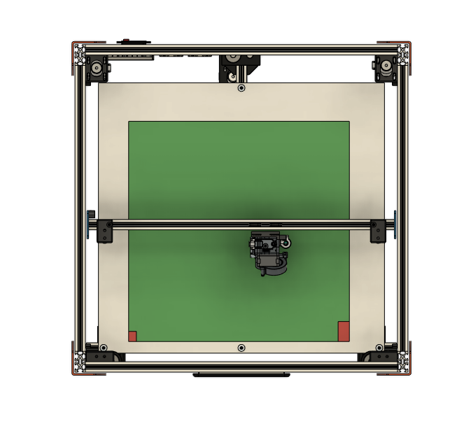
at the moment I am building a new machine. Due to the design of the z-axis and the Tool head there are 2 corners (marked red in picture) which the print head is not able to reach because it would cause a crash with the z-axis top mount.
Is there any way in RRF3 to restrict movements into this area so the printhead won't move there?
Thanks for your help.
Max
Thank you!
Is there any "feedback" from the M291 command I could use in conditional code?
M291 P"If you're satisfied with the z-calibration results push "OK", if z-calibration shall be repeated push "cancel"" R"Calibration of z-Position" S2
So I can coordinate if thh z_satisfied variable should be set to true or false according to the user-input?
Greets
Max
MacNite 12 Mar 2021, 11:59
Maybe some of you have seen my post of trying to built a calibration routine for the CR3D Idex machines.
https://forum.duet3d.com/topic/21803/calibration-routine-for-dual-extruder-printers
This thread did not get much tracktion...probably due to the kind of complex nature of such a routine. So I'll try to break down the problem into smaller chunks.
The "newest" problem is the user-interaction.
After completing the z-calibration the user should be asked, if he is satisfied with the results. Otherwise it should be repeated.
	; start z-calibration routine
while z_satisfied = false
    M291 P"Put a piece of Paper on the built plate" R"Calibration of z-Position" S2
    T1
    M291 P"Move the Bed up using the buttons until the paper slightly graps on the nozzle" R"Calibration of z-Position- Tool 1" S3 X0 Y0 Z1
    G10 P1 Z{-axes[3].position}		; set z-offset of Tool1 to value from last calibration
    M500 P10                        ; safe Tool1 offset
    G1 Z5
    T2
    M291 P"Move the Bed up using the buttons until the paper slightly graps on the nozzle" R"Calibration of z-Position- Tool 2" S3 X0 Y0 Z1
    G10 P2 Z{-axes[3].position}		; set z-offset of Tool2 to value from last calibration
    M500 P10                        ; safe Tool2 offset
    G1 Z5
    M291 P"Remove Piece of Paper" R"Calibration of z-Position" S2

	; start test print for z-calibration
    ;M98 P"z_test_print.g"				; Print z-calibration lines

	; ask user if he is satisfied
	M291 P"Are you satisfied with the z-calibration results or should this step be repeated" R"Calibration of z-Position" S2
	; If M291_input = yes
    ;    z_satisfied = true
    ;else
    ;    z_satisfied = false
Is it possible to get a "feedback" and or yes/no-buttons with M291 or is there any other way of "user-interaction"?
Greets
Max
up!
I really want this feature - or a workaround - as well ")
Thank you very much!
Sometimes I just feel dumb...
Maybe some of you have seen my post of trying to built a calibration routine for the CR3D Idex machines.
https://forum.duet3d.com/topic/21803/calibration-routine-for-dual-extruder-printers
This thread did not get much tracktion...probably due to the kind of complex nature of such a routine. So I'll try to break down the problem into smaller chunks.
Is there any way to store the tool offsets after doing
a) z-offset-calibration
b) x-y-offset-clibration
M500 does not safe it. I tried something like that (writing to a file on the sd-card).
T1
M291 P"Move the Bed up using the buttons until the paper slightly graps on the nozzle" R"Calibration of z-Position- Tool 1" S3 X0 Y0 Z1
M28 tool1offset_z.g 			; generate file for z-offset Tool1
G10 P1 Z{-axes[3].position}		; set z-offset of Tool1 to value from last calibration
M29
There are 2. Problems with this:
G10 P1 Z{-axes[3].position}
into the file and not (i.e.)
G10 P1 Z-2.5
Any ideas / solutions / different ways?
thanks for your help!
Hey guys,
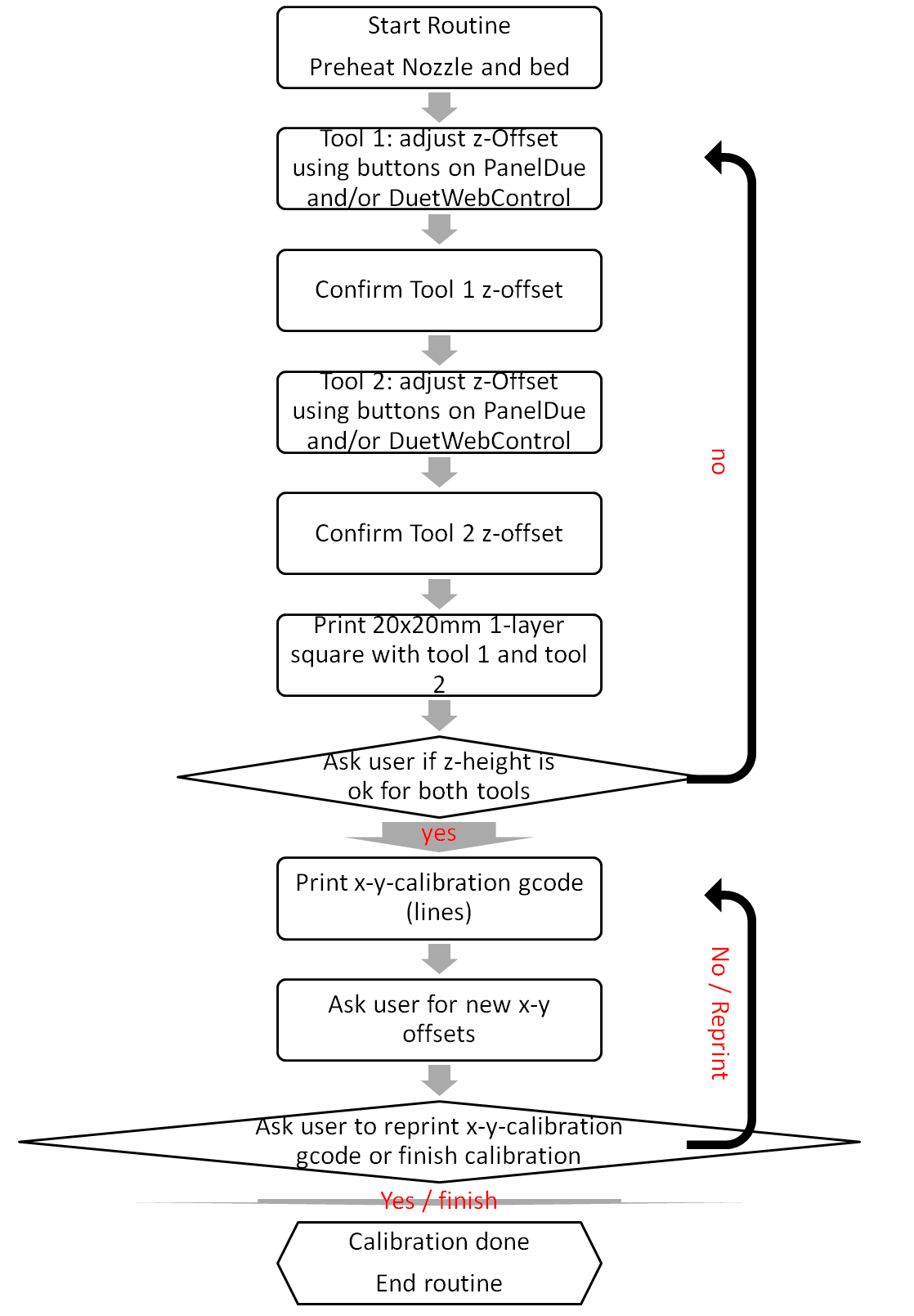
I want to create a calibration routine for the IDEX and LiftingHotend printers I develope together with @CR3D .
I already asked here, but I think that was the wrong category.
https://forum.duet3d.com/topic/21737/rrf3-dual-extruder-calibration-tool-and-nozzle-offset/5?_=1614279002208
For this I want to "built" a routine which shall work like the following diagram:
I have multiple issues at the moment - I added my code below:
G10 P1 Z{-axes[3].position}
But I want it to be
G10 P1 Z-2.2
Additionally these files are generated in the /gcode folder. I want them to be hidden or inside the macro folder so the user does not accidentally delete them.
3. Is there a way to ask / query the firmware if filament is loaded. Primarly I want to ask the firmware, if the filament runout sensor is triggerd. I really don't know how to "properly" use the object model...maybe it is in there and I am just blind...
; add tool1offset_z.g and tool2offset_z.g to config.g with M98 P"tool1offset_z.g" M98 P"tool2offset_z.g"
; built z-calibration gcode - 20x20 square
; built x-y-calibration gcode

M291 P"This will reset all previous defined tool offsets to the default values. Do you want to continue?" R"Calibration of Tool Offsets" S3
;M561                    			; clear any bed transform
G28
M104 S215 T1						; active & standby Temperature for Tool 1 200°C
M104 S215 T2						; active & standby Temperature for Tool 2 200°C
M140 S65							; set Bed Temperature to 65°C
G10 P1 X-10 Y0 Z0					; set Tool 1 offsets to default values
G10 P2 X10 Y0 Z0					; set Tool 1 offsets to default values
G1 Z5

	; check if Filament is loaded in tool 1
;if FILAMENT_LOADED_T1 == TRUE Then
;ELSE
;T1
;M701 S"PLA"
	; chek if Filament is loaded in tool 2
;if FILAMENT_LOADED_T2 == TRUE Then
;ELSE
;T2
;M701 S"PLA"

	; start z-calibration routine
;##marker-mc-markface
M291 P"Put a piece of Paper on the built plate" R"Calibration of z-Position" S2
T1
M291 P"Move the Bed up using the buttons until the paper slightly graps on the nozzle" R"Calibration of z-Position- Tool 1" S3 X0 Y0 Z1
M28 tool1offset_z.g 			; generate file for z-offset Tool1
G10 P1 Z{-axes[3].position}		; set z-offset of Tool1 to value from last calibration
M29
G1 Z5
T2
M291 P"Move the Bed up using the buttons until the paper slightly graps on the nozzle" R"Calibration of z-Position- Tool 2" S3 X0 Y0 Z1
M28 tool2offset_z.g 			; generate file for z-offset Tool1
G10 P2 Z{-axes[3].position}		; set z-offset of Tool2 to value from last calibration
M29
G1 Z5
M291 P"Remove Piece of Paper" R"Calibration of z-Position" S2

	; start test print for z-calibration
;M98 P"z_test_print.g"				; Print z-calibration lines

	; ask user if he is satisfied
;If-Statement to ask user if z-offset is fine or z-calibration has to re-run, for rerun re_turn to ##marker-mc-markface

	;start xy offset calibration


; to come....
Thank you for your help. I think together we might be able to built a routin that will every dual extruder printer which uses RRF.
Stay safe.
Max