@droftarts Thanks! I apologize for the extraneous detail and having the nugget of the datasheet axis orientation at the bottom of the post - might have been good to lead with that instead.
Posts made by sebkritikel
-
RE: SZP Accelerometer Orientation - Incorrect Silkscreen?posted in General Discussion
-
SZP Accelerometer Orientation - Incorrect Silkscreen?posted in General Discussion
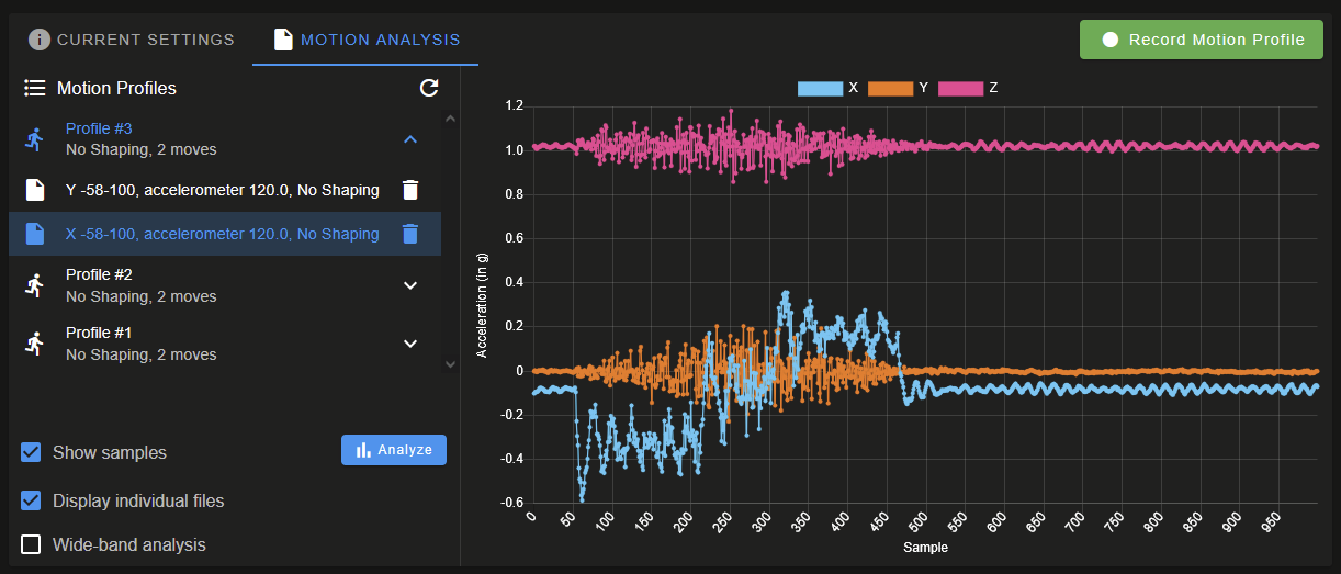
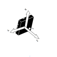
All boards on 3.6.0-rc.1+3. Commissioning my Stratasys Dimension conversion, and using the SZP (v1.0 revision) was the easiest way to attach an accelerometer. I'm finding that the results displayed in the input shaping plugin do not match the expected results based on the silkscreen axis. Silkscreen axis appears to be rotated 90° clockwise about the Z-axis. Printer and SZP are oriented as such:
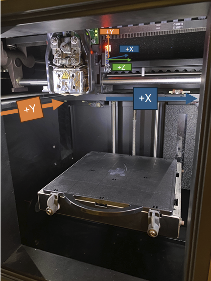
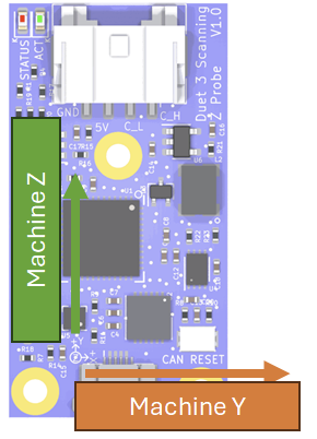
Machine X (viewing from the front) is negative to the left, positive to the right. Machine Y is negative towards the front (door), positive towards the back - pretty standard setup.SZP is installed with the 4-pin JST PA connector pointed UP - meaning, per the silkscreen:
- Accelerometer Y -> machine Z
- Accelerometer X -> machine Y
- Accelerometer Z -> Machine X
 !
!Per M955, with accelerometer (top of board/chip) Z oriented towards machine +X, first digit of
Iis0, and with board +X oriented towards machine +Y, the second digit should be1. Towards the end of my config.g I haveM955 P120.0 I01After a fresh power up,
M955 P120.0reports:Accelerometer 120:0 type LIS2DW with orientation 1 samples at 800Hz with 14-bit resolutionInput shaping plugin results for
I01
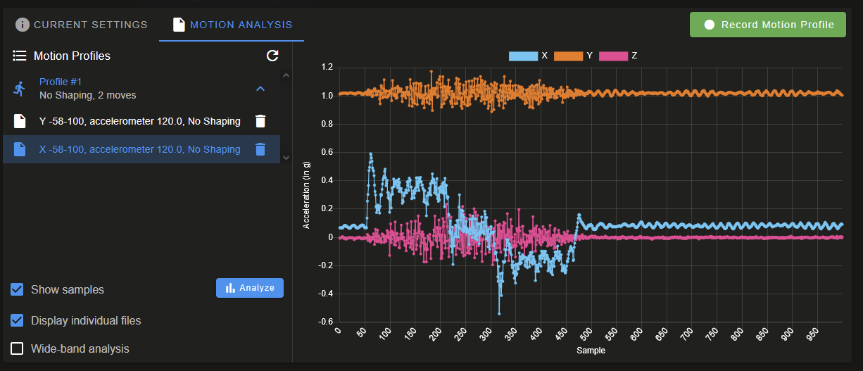
The graph's X-axis does show accelerations during X moves, however right away we see that the graph's Y results are reporting gravity. During Y moves, accelerations are instead displayed on the graph Z-axis.
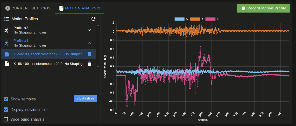
Changing this to
I42, gives the expect chart results, meaning:- Accelerometer Y -> machine Y
- Accelerometer X -> machine Z
- Accelerometer Z -> Machine -X
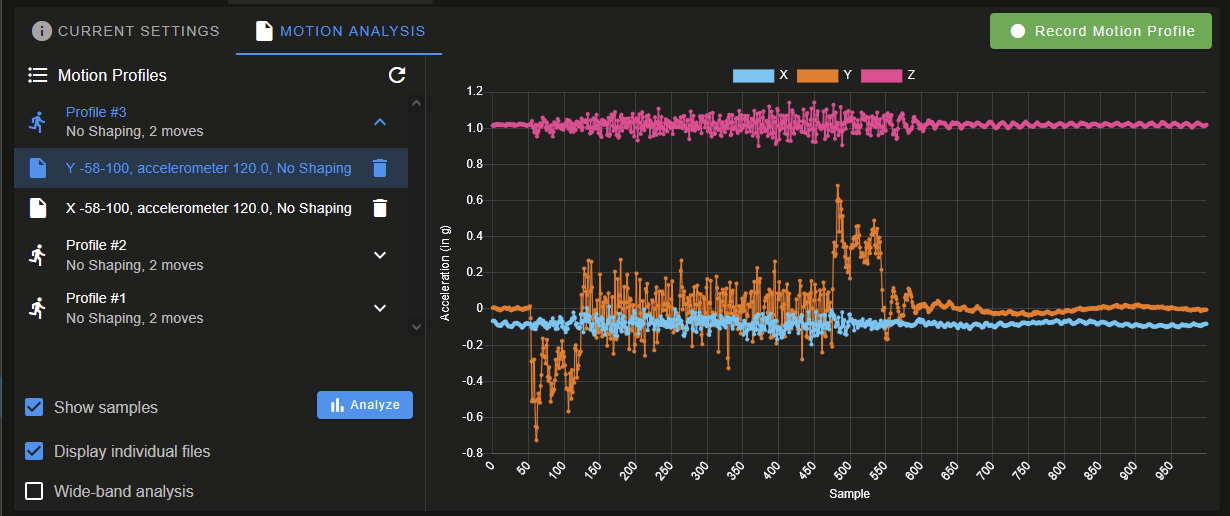
Here is
I20, leading me to believe the firmware needs to be corrected (or silkscreen ). I can try and find where the orientation is defined later.
The graphs for
I20match the orientation shown in the LIS2DW12 datasheet vs. the silkscreen:
-
[3.6.0-beta.3+1] Step timing error occurred on drive 0 (code 2).posted in Beta Firmware
I recognize an RC is out, and should update to that. Error here may already be solved in future builds, but wanted to post anyways.
Commissioning a 'new' build - 6HC, Sammy-C21 as an expansion driving an external extruder motor. Walked up to the printer and witnessed the halt in real time.
Paused in layer 86 of the attached print file: CFFFP_3DBenchy.gcode
Error: Movement halted because a step timing error occurred on drive 0 (code 2). Please reset the controller.
Error: Extra info=-9.765625e-4
M122
=== Diagnostics ===
RepRapFirmware for Duet 3 MB6HC version 3.6.0-beta.3+1 (2025-01-20 20:04:23) running on Duet 3 MB6HC v1.02b or later (standalone mode)
Board ID: 08DJM-9P63L-DJMSS-6J1D8-3SD6T-9VDZ8
Used output buffers: 1 of 40 (33 max)
=== RTOS ===
Static ram: 136892
Dynamic ram: 129160 of which 0 recycled
Never used RAM 76300, free system stack 130 words
Tasks: NETWORK(1,ready,33.1%,180) ETHERNET(5,nWait 7,0.1%,316) HEAT(3,nWait 6,0.0%,323) Move(4,invalid,0.5%,215) TMC(4,nWait 6,3.0%,341) CanReceiv(6,nWait 1,0.0%,769) CanSender(5,nWait 7,0.0%,327) CanClock(7,delaying,0.0%,341) MAIN(1,running,63.3%,440) IDLE(0,ready,0.0%,29) USBD(3,blocked,0.0%,149), total 100.0%
Owned mutexes:
=== Platform ===
Last reset 00:56:44 ago, cause: software
Last software reset at 2025-03-28 16:39, reason: User, Gcodes spinning, available RAM 76492, slot 2
Software reset code 0x0003 HFSR 0x00000000 CFSR 0x00000000 ICSR 0x00400000 BFAR 0x00000000 SP 0x00000000 Task MAIN Freestk 0 n/a
Error status: 0x00
MCU temperature: min 41.2, current 42.3, max 42.6
Supply voltage: min 47.5, current 48.0, max 48.3, under voltage events: 0, over voltage events: 0, power good: yes
12V rail voltage: min 12.1, current 12.3, max 12.5, under voltage events: 0
Heap OK, handles allocated/used 99/8, heap memory allocated/used/recyclable 2048/156/40, gc cycles 0
Events: 0 queued, 0 completed
Date/time: 2025-03-28 17:36:38
Slowest loop: 211.09ms; fastest: 0.07ms
USB interrupts 2
=== Storage ===
Free file entries: 19
SD card 0 detected, interface speed: 25.0MBytes/sec
SD card longest read time 2.8ms, write time 70.4ms, max retries 0
=== Move ===
Segments created 71, maxWait 485690ms, bed comp in use: none, height map offset 0.000, hiccups added 0/0 (0.00/53.45ms), max steps late 1, ebfmin 0.00, ebfmax 0.00
Pos req/act/dcf: 483.00/384/1.00 1953.00/2046/-1.00 11564.00/11564/-0.00
next step interrupt due in 214 ticks, disabled
Driver 0: standstill, SG min 0, mspos 648, reads 58364, writes 65 timeouts 3
Driver 1: standstill, SG min 0, mspos 24, reads 58364, writes 65 timeouts 3
Driver 2: standstill, SG min 0, mspos 696, reads 58364, writes 65 timeouts 3
Driver 3: standstill, SG min n/a, mspos 8, reads 58385, writes 44 timeouts 3
Driver 4: standstill, SG min n/a, mspos 8, reads 58385, writes 44 timeouts 3
Driver 5: standstill, SG min n/a, mspos 8, reads 58385, writes 44 timeouts 3
Phase step loop runtime (us): min=0, max=501, frequency (Hz): min=672, max=10416
=== DDARing 0 ===
Scheduled moves 55178, completed 55119, LaErrors 0, Underruns [0, 0, 0]
Segments left 1, axes/extruders owned 0x80000007, drives owned 0x80000007
Code queue is empty
=== DDARing 1 ===
Scheduled moves 0, completed 0, LaErrors 0, Underruns [0, 0, 0]
Segments left 0, axes/extruders owned 0x00000000, drives owned 0x00000000
Code queue is empty
=== Heat ===
Bed heaters -1 -1 -1 -1 -1 -1 -1 -1 -1 -1 -1 -1, chamber heaters 0 -1 -1 -1 -1 -1 -1 -1, ordering er=== GCodes ===
Movement locks held by null, null
HTTP is idle in state(s) 0
Telnet is idle in state(s) 0
File is doing "G1 X19.803 Y1.127 E0.01883" in state(s) 0
USB is idle in state(s) 0
Aux is idle in state(s) 0
Trigger is idle in state(s) 0
Queue is idle in state(s) 0
LCD is idle in state(s) 0
SBC is idle in state(s) 0
Daemon is idle in state(s) 0
Aux2 is idle in state(s) 0
Autopause is idle in state(s) 0
File2 is idle in state(s) 0
Queue2 is idle in state(s) 0
=== CAN ===
Messages queued 80102, received 27247, lost 0, ignored 0, errs 2684, boc 0
Longest wait 1ms for reply type 6018, peak Tx sync delay 46148, free buffers 50 (min 49), ts 16135/16132/0
Tx timeouts 0,0,2,0,0,0 last cancelled message type 30 dest 127
=== Network ===
Slowest loop: 204.57ms; fastest: 0.03ms
Responder states: MQTT(0) HTTP(0) HTTP(0) HTTP(0) HTTP(0) HTTP(0) HTTP(0) FTP(0) Telnet(0) Telnet(0)
HTTP sessions: 2 of 8
= Ethernet =
Interface state: active
Error counts: 0 0 0 1 0 0
Socket states: 6 2 2 2 2 0 0 0 0
=== WiFi ===
Interface state: disabled
Module is disabled
Failed messages: pending 0, notrdy 0, noresp 0
Socket states: 0 0 0 0 0 0 0 0
=== Multicast handler ===
Responder is inactive, messages received 0, responses 0
M122 B124
Diagnostics for board 124:
Duet SAMMYC21 firmware version 3.6.0-beta.3+1 (2025-01-20 20:01:57)
Bootloader ID: not available
All averaging filters OK
Never used RAM 9444, free system stack 71 words
Tasks: Move(3,nWait 7,0.2%,86) HEAT(2,nWait 6,0.1%,128) CanAsync(5,nWait 4,0.0%,66) CanRecv(3,nWait 1,0.1%,70) CanClock(5,nWait 1,0.0%,58) MAIN(1,running,98.3%,436) IDLE(0,ready,0.0%,26) AIN(2,delaying,1.3%,120), total 100.0%
Owned mutexes:
Last reset 01:11:39 ago, cause: software
Last software reset data not available
Moves scheduled 50341, hiccups 697 (53.45/53.45ms), segs 23, step errors 0 (types 0x0), maxLate 0 maxPrep 272, ebfmin 0.00 max 0.00
Peak sync jitter 3/8, peak Rx sync delay 293, resyncs 0/0, no timer interrupt scheduled, next step interrupt due in 3582982220 ticks, disabled
MCU temperature: min 39.0C, current 39.2C, max 39.8C
Driver 0: pos 9953144, 3230.8 steps/mm
Last sensors broadcast 0x00000000 found 0 6 ticks ago, 0 ordering errs, loop time 0
CAN messages queued 34423, send timeouts 0, received 87925, lost 0, ignored 0, errs 0, boc 0, free buffers 18, min 18, error reg 0
dup 0, oos 0/0/0/0, bm 0, wbm 0, rxMotionDelay 466, adv 35536/47502
Accelerometer: none
Inductive sensor: not found
I2C bus errors 0, naks 0, contentions 0, other errors 0
config.g
; Default config.g template for DuetPi ; Replace this with a proper configuration file (e.g from https://configtool.reprapfirmware.org) ; Display initial welcome message ;M291 P"Please go to <a href=""https://www.duet3d.com/StartHere"" target=""_blank"">this</a> page for further instructions on how to set it up." R"Welcome to your new Duet 3!" S1 T0 ; Enable network if {network.interfaces[0].type = "ethernet"} M552 P192.168.100.56 S1 else M552 I1 S1 M552 I1 S1 ; enable wifi G4 S2 ;wait for expansion boards to start ; Drives M569 P0 S1 ;physical drive 0 goes backwards, X-Axis M569 P1 S0 ;physical drive 1 goes forwards, Y-Axis M569 P2 S1 ;physical drive 2 goes forwards, Z-Axis M569 P124.0 S0 T0:0:0:0 ;external driver on sammy M584 X0 Y1 Z2 E124.0 ;set drive mapping M350 X16 Y16 Z16 E16 I1 ;configure microstepping with interpolation M92 X53.33 Y134 Z629.864 E3230.77 ;set steps per mm was 1011.99 then 1594.6, then 642.61 M566 X600 Y600 Z60 E3000 ;set jerk M203 X30000 Y18000 Z1200 E1800.00 ;set max speeds (mm/min) M201 X2500 Y3500 Z2000 E3000 ;set max accelerations (mm/s^2) M201.1 X750 Y750 Z2000 E3000 ;max special acceleration move (homing) M906 X1800 Y2600 Z2600 I30 ;set motor currents (mA) and motor idle percent M84 S30 ;set idle timeout M208 X-138.3 Y-137.5 Z-2 S1 ;set axis minima M208 X160.4 Y178.5 Z325.116 S0 ;set axis maxima ; Toggle nozzle min - -163.2 , 206 max ; X EOT toggles at 181.2 ; Y EOT at 182.4 ;purge bucket near middle - x162.5, y155.5 ;z probe left toggle -136.5 ;z probe right toggle 197.5 ;from build plate center, model (right) offset x=+20.8 (too far right), support is +40.8 ;from build plate center, Y offset = -23 (too far forward) ;Z bottom (EOT) 325.1 ;Endstops M574 X1 S1 P"!io0.in" ; X home limit (low side) M574 Y1 S1 P"!io1.in" ; Y home limit (low side, toward front of printer M574 Z2 S1 P"!io6.in" ; assign Z EOT to x endstop on high side ; Z-Probe M558 P5 H5 F1200:200 T5000 C"!io2.in" ; Z probe, set dive height, probe speed and travel speed ;G31 P1000 X-46 Y-74 Z0.896 G31 P1000 X-24 Y-73 Z1.365 ;G31 P1000 X24 Y96 Z0.896 ; set Z probe trigger value, offset and trigger height M557 X-135:135 Y-135:65 P5:5 ; define mesh grid. The whole bead cannot be probed due to the position of the probe. ; Head Blower Fan M950 P0 C"!out4" M42 P0 S0 ; enable blower ; Extruder Motor Enable M950 P1 C"!out5" M42 P1 S0 ; Touch Power Enable M950 P2 C"!out6" M42 P2 S0 ; Door Enable M950 P3 C"io6.out" M42 P3 S0 ; LED Lights Enable M950 P4 C"io2.out" M42 P4 S1 ;S1 to turn on! ; Gecko Reset M950 P5 C"io0.out" M42 P5 S0 ; Thermocouples M308 S0 A"Chamber Test" P"temp0" Y"linear-analog" F0 B-42 C113 M308 S1 A"Model Test" P"temp1" Y"linear-analog" F0 B12.5 C328 M308 S2 A"Support Test" P"temp2" Y"linear-analog" F0 B12.5 C328 ; Heaters M140 H-1 ;Disable bed heater M950 H0 C"!out7" T0 ; chamber, sensor 0 M141 H0 ; map chamber to heater 0 M143 H0 S85 ; set temperature limit for heater 0 to 85C M570 H0 P30 T10 ; Increase fault delay to 30s, decrease temperature fault to 10c M950 H1 C"!out8" T1 ; model, sensor 1 M143 H1 S320 M570 H1 P30 ; set fault time delay to 30s for heater 1 M950 H2 C"!out9" T2 ; support, sensor 2 M143 H2 S320 ; set temperature limit for heater 1 to 320C M570 H2 P30 ; set fault time delay to 30s for heater 2 ; Tools M563 P0 S"Model" D0 H1 ; define tool 0 G10 P0 X0 Y0 Z0 ; set tool 0 axis offsets G10 P0 R0 S0 ; set initial tool 0 active and standby temperatures M563 P1 S"Support" D0 H2 ; define tool 1 G10 P1 X-20 Y0 Z0 ; set tool 1 axis offsets G10 P1 R0 S0 ; set initial tool 1 active and standby temperatures ; Gecko Error In M950 J0 C"124.pa04" ;gecko error in ; Head Thermostat Status M950 J1 C"124.pa05" ; Door In M950 J2 C"124.pa06" ; Print Head Support Toggle M950 J3 C"124.pa07" ; Print Head Model Toggle M950 J4 C"124.pa19" ; X-axis EOT M950 J5 C"!io3.in" ; Y-axis EOT M950 J6 C"!io4.in" ; Z-axis Home M950 J7 C"!io5.in" ; Z-axis EOT ;M950 J8 C"!io6.in" ; Print Head Temp Alarm M950 J9 C"!io7.in" ; Chamber Temp Alarm M950 J10 C"!io8.in" ;M581 Tx P5:6:7:8 M501 ;config g M302 S200 R200 M98 P"globals.g" -
RE: Stratasys uPrint Duet Complete Retrofitposted in My Duet controlled machine
@Thatguywithathing Good question! From a long term sustainment perspective, keeping the majority of the Stratasys parts is a risk. If something breaks, or a consumable (nozzle, or liquifier tip as Stratasys calls them, etc) is needed, head to ebay and hope you can find it. Over the years when working on some other 3D printer projects, I've picked up a few random spares off ebay, so for me the risk is low (for now!).
In my case, some pros:
- Limit switches, end of axis switches, door switch and head toggle switches already exist, as well as their wiring. Can reuse
- Dual extrusion system is repeatable and reliable. Can reuse. (I also quite like dual/multiextrusion, be it this, IDEX, etc. Would like to maintain this as a dual extrusion system).
- Infrastructure to power/switch chamber AC heaters already exists, can reuse
- 120V heaters for the model, support material are present, as well as the ability to drive them.
- Existing nozzles (liquifier tips) work well in heated chambers, no concerns about clogging or heat creep
- Cost - reusing as much as possible is likely the most cost efficient approach (assuming we start with a functional printer).
Added Capability
- I added a small 48VDC power supply to power the Duet 6HC. This grants some additional speed for the X,Y, and Z stepper motors vs. stock 24V.
Cons:
- Existing tool head is large & heavy. Yes, it offers great dual extrusion capability, but a smaller print head (or somehow 2x for IDEX) could zip around the chamber and offer excellent prints.
Personal Challenges:
- Closed-loop DC motor control (for the extruder) - a fun personal challenge for me. DC motor control isn't something RRF (or other printer firmwares) natively support (RRF supports closed loop stepper motors via the 1HCL expansion board). Using a Geckodrive G320x with step/dir from an expansion board (could be a 1XD from Duet, or a Sammy-C21, etc) pretty much works immediately, but when driving the DC motor directly, you'll either see the driver fault out, or the motor will see excessive thermal rise - the G320x just isn't the right tool for this type of motor. I'm having much better luck with a Nucleo-64 running SimpleFOC's SimpleDC library.
- Custom PCB. The conversion can be done simply by running jumper wires from the Duet(s) to the PDB, but I wanted to dig a bit deeper into the world of electronics design.
Were the printer non-functional (print head assembly missing, no PDB, etc) then I for sure would have taken an alternative approach to converting it over to RRF. Your conversion is extraordinarily well done, and highlights how powerful modern controller boards are compared to the ancient boards in the stock machines!
-
RE: Stratasys uPrint Duet Complete Retrofitposted in My Duet controlled machine
@hub3d This year I kicked off my Dimension 1200 conversion to the Duet 3 ecosystem. I've made been plenty of progress since my last post in this thread, aim to post an update soon. https://forum.duet3d.com/topic/37434/dueprint-with-a-duet-3-6hc-stratasys-dimension-conversion
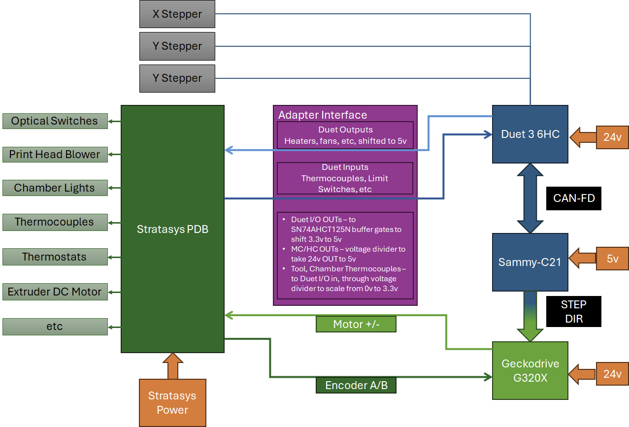
Goal is to use as much existing infrastructure from the original printer as possible - only items removed were the Stratasys SBC and control board. X, Y, Z motors wire directly to the Duet 3 6HC, and the extruder motor (at the time the picture was taken) is ultimately controlled by 6HC -> CAN-FD -> Sammy-C21 -> Step/Dir -> Geckodrive G320x -> PWM -> Stratasys PDB -> Extruder motor. Right now I'm working on an alternative to the Geckodrive G320x, as it works in a pinch, but its not the right tool for the job.
@hub3d said in Stratasys uPrint Duet Complete Retrofit:
Best part, I'd LOVE to get rid of the dedicated 20A circuit that the Fortus needs. Now that it's in my home and not at the shop, I don't really have a dedicated circuit at the moment.
I thought the Fortus 250mc only required a 15a circuit?
-
RE: [3.6.0-rc.1] EXP1HCL V1.0a io1.out PWM Issuesposted in Beta Firmware
@dc42 said in [3.6.0-rc.1] EXP1HCL V1.0a io1.out PWM Issues:
@sebkritikel there was a firmware bug. Please try the 3.6.0-rc.1+1 version at https://www.dropbox.com/scl/fo/0xdvvzgqfrs5abyk75ss8/AL3i6s7z9UacEGYsxiR7pXw?rlkey=xpm61w2jlyqlawwjzy4zsq2lt&dl=0 which is compatible with 3.6.0-rc.1 or rc.1+1 firmware on the main board. This EXP1HCL build contains an experimental feature but that should not affect you unless you are using a linear composite encoder.
Thanks! Just tested both boards with rc.1+1 (mainboard and 1HCLs) and io1.out works as expected.
-
RE: Would RRF be suitable for an automatic storage machine?posted in General Discussion
@SimonM Two thoughts from me:
- For easy I/O expansion, the Sammy-C21 is a great piece of kit, connecting to your mainboard via CAN-FD. Depending on your needs, this would likely need to go onto a custom PCB (with some pull-up/pull-down resistors on inputs/outputs, etc) https://docs.duet3d.com/Duet3D_hardware/Duet_3_family/Using_the_Sammy-C21_development_board_with_Duet_3
- The BtnCmd plugin for Duet Web Control is amazing for creating custom dashboards. Charts, buttons to toggle outputs, input monitoring, buttons to launch macros, etc - pretty much only limited by your imagination.
-
RE: [3.6.0-rc.1] Code 6 Error, V1.02 6HCposted in Beta Firmware
@dc42 said in [3.6.0-rc.1] Code 6 Error, V1.02 6HC:
@sebkritikel at the time it was trying to extrude 100mm of filament at 5mm/sec and it was almost certainly an extruder-only ove. A few questions:
-
Do you have such a move in the gcode you run prior to printing, or at the start of a print, perhaps to load or prime filament?
-
Had the printer already done a lot of printing since power up when this occurred?
-
Are you the user who reported the filament position showing as negative after a number of prints?
Ah interesting! This Code 6 coincided with me upgrading Cura to 5.9.1. This resulted in some (unfortunate) changes in the print start and print end configurations. One of which was a print end change (in Cura) that resulted in changing to absolute extrusion once the print was completed and then resetting the extrusion amount to zero (resulting in the extruder running backwards for a very long time). I believe I noticed this issue after I reported the Code 6 error from this thread.
To answer the questions directly:
- I may have, via DWC or the PanelDue, commanded a 100mm extrusion at 5mm, prior to starting the print (I did manually load filament, but unsure if it was directly before this error code; or several hours previously).
- I believe I had done ~ 1.5hrs of printing before hand. After I corrected my Cura config (see above) I went on to do 5+ hours of printing over the weekend without incident
- No, I am not that user.
-
-
[3.6.0-rc.1] Code 6 Error, V1.02 6HCposted in Beta Firmware
Occurred at the start of a print - unsure if it was before the homing routine, or before it went to actually lay down plastic.
Error: Code 6 move error: info=0.00, seg: s=70911352 t=14999375 d=41498.27 u=2.7667e-3 a=0.0000e+0 f=1dM122
=== Diagnostics ===
RepRapFirmware for Duet 3 MB6HC version 3.6.0-rc.1 (2025-02-28 15:00:13) running on Duet 3 MB6HC v1.02 or 1.02a (standalone mode)
Board ID: 08DJM-9P63L-DJ3S0-7J1DD-3SN6L-9VMMA
Used output buffers: 1 of 40 (40 max)
=== RTOS ===
Static ram: 137420
Dynamic ram: 131184 of which 32 recycled
Never used RAM 69612, free system stack 110 words
Tasks: NETWORK(1,ready,32.3%,159) ETHERNET(5,nWait 7,0.1%,311) HEAT(3,nWait 6,0.0%,323) TMC(4,nWait 6,3.1%,341) CanReceiv(6,nWait 1,0.0%,771) CanSender(5,nWait 7,0.0%,334) CanClock(7,delaying,0.0%,341) MAIN(1,running,64.4%,103) IDLE(0,ready,0.0%,29) USBD(3,blocked,0.0%,144), total 100.0%
Owned mutexes:
=== Platform ===
Last reset 01:42:57 ago, cause: power up
Last software reset at 2025-03-06 15:51, reason: User, Gcodes spinning, available RAM 75848, slot 1
Software reset code 0x0003 HFSR 0x00000000 CFSR 0x00000000 ICSR 0x00400000 BFAR 0x00000000 SP 0x00000000 Task MAIN Freestk 0 n/a
=== Storage ===
Free file entries: 19
SD card 0 detected, interface speed: 25.0MBytes/sec
SD card longest read time 5.2ms, write time 17.0ms, max retries 0
=== Move ===
Segments created 242, maxWait 4091056ms, bed comp in use: none, height map offset 0.000, hiccups added 0/0 (0.00/0.00ms), max steps late 1, ebfmin 0.00, ebfmax 0.00
Pos req/act/dcf: 4000.00/4000/-0.00 1920.00/1920/0.00 128819.00/128819/0.00 26700.00/26700/0.00
Next step interrupt due in 299 ticks, disabled
Driver 0: standstill, SG min 0, mspos 552, reads 34398, writes 63 timeouts 4
Driver 1: standstill, SG min 0, mspos 232, reads 34398, writes 63 timeouts 4
Driver 2: standstill, SG min 0, mspos 1000, reads 34398, writes 63 timeouts 4
Driver 3: standstill, SG min 0, mspos 24, reads 34398, writes 63 timeouts 4
Driver 4: standstill, SG min 0, mspos 56, reads 34404, writes 57 timeouts 4
Driver 5: standstill, SG min 0, mspos 24, reads 34398, writes 63 timeouts 4
Phase step loop runtime (us): min=0, max=116, frequency (Hz): min=670, max=20833
=== Heat ===
Bed heaters 0 -1 -1 -1 -1 -1 -1 -1 -1 -1 -1 -1, chamber heaters -1 -1 -1 -1 -1 -1 -1 -1, ordering errs 0
=== GCodes ===
Movement locks held by File, null
HTTP is idle in state(s) 0
Telnet is idle in state(s) 0
File is doing "t1" in state(s) 0
USB is idle in state(s) 0
Aux is idle in state(s) 0
Trigger is idle in state(s) 0
Queue is idle in state(s) 0
LCD is idle in state(s) 0
SBC is idle in state(s) 0
Daemon is idle in state(s) 0
Aux2 is idle in state(s) 0
Autopause is idle in state(s) 0
File2 is idle in state(s) 0
Queue2 is idle in state(s) 0
=== Filament sensors ===
Driver 31: no data received, errs: frame 0 parity 0 ovrun 0 pol 0 ovdue 0
=== CAN ===
Messages queued 53990, received 74124, lost 0, ignored 0, errs 4966, boc 0
Longest wait 2ms for reply type 6027, peak Tx sync delay 24151, free buffers 50 (min 49), ts 29280/29275/0
Tx timeouts 0,0,4,0,0,0 last cancelled message type 30 dest 127
=== Network ===
Slowest loop: 692.36ms; fastest: 0.03ms
Responder states: MQTT(0) HTTP(0) HTTP(0) HTTP(0) HTTP(0) HTTP(0) HTTP(0) FTP(0) Telnet(0) Telnet(0)
HTTP sessions: 1 of 8
=== Multicast handler ===
Responder is inactive, messages received 0, responses 0
= Ethernet =
Interface state: active
Error counts: 0 0 0 0 0 0
Socket states: 6 2 2 2 2 0 0 0 0
=== WiFi ===
Interface state: disabled
Module is disabled
Failed messages: pending 0, notrdy 0, noresp 0
Socket states: 0 0 0 0 0 0 0 0
Config.g (its ugly)
M98 P"/sys/GlobalVars.g" ; General preferences G90 ; Send absolute coordinates... M83 G4 S1 ; wait for CANBUS to start ; Enable network if {network.interfaces[0].type = "ethernet"} M552 P0.0.0.0 S1 else M552 S1 M586 P0 S1 ; Enable HTTP M586 P1 S0 ; Disable FTP M586 P2 S0 ; Disable Telnet M550 P"Duet3 IDEX" ; Set machine name ;Enable PanelDue M575 P1 S1 B57600 ; Type M669 K0 ; Drives M569 P0 S1 ; Physical drive 0 goes forwards X M569 P1 S0 ; Physical drive 1 goes backwards Y DISABLE FOR CLOSED LOOP ;M569.1 P50.0 T2 C1000 S200 R200 I2000 D0.075 V1000.0 A100000.0 ; tweaked 1/27 ENABLE FOR CLOSED LOOP ;M569 P50.0 D4 S0 ;ENABLE FOR CLOSED LOOP G4 S1 ; wait for CANBUS to start M569 P2 S0 ; Physical drive 2 goes backwards Z M569 P3 S0 ; Physical drive 3 goes Backwards U M569 P4 S0 ; Physical drive 4 goes forwards E0 M569 P5 S1 ; Physical drive x goes forwards E1 ;M584 X0 Y50.0 Z2 U3 E4:5 ; create the U axis and assign stepper driver 5 ENABLE FOR CLOSED LOOP M584 X0 Y1 Z2 U3 E4:5 ; create the U axis and assign stepper driver 5 DISABLE FOR CLOSED LOOP M350 X16 Y16 Z16 U16 E16:16 I1 ; Configure microstepping with interpolation removed 32x for Y ;M92 X100.00 Y96 Z1280.00 U100.00 E2292.00:415.00 ; changed 192steps/mm for Y back to 96 after changing microstepping back to 16 M92 X100.00 Y96 Z1280.00 U100.00 E415.00:415.00 M566 X600.00 Y600.00 Z500.00 U600.00 E36000.00:36000.00 ; Set maximum instantaneous speed changes (mm/min) - the extruder jerk settings are a mistake... but I also haven't seen any downsides to them. original M566 P1 ;Jerk Policy M203 X36000.00 Y36000.00 Z1320.00 U36000.00 E6000.00:3000.00 ; Set maximum speeds (mm/min original M201 X4000.00 Y4000.00 Z450.00 U4000.00 E3000.00:3000.00 ; Set accelerations (mm/s^2) ;M906 X2100.00 Y3200.00 Z2400.00 U2100.00 E350.00:1960.00 I30 ; Set motor currents (mA) and motor idle factor in per cent original M906 X2100.00 Y3200.00 Z2400.00 U2100.00 E1960.00:1960.00 I30 ; Set motor currents (mA) and motor idle factor in per cent original M84 S30 ; Set idle timeout ; Axis Limits ;M208 X-260 Y-220 Z-4.65 U-150 S1 ; Set axis minima ;M208 X156 Y220 Z210.35 U267 S0 ; Set axis maxima M208 X{global.minx} Y{global.miny} Z{global.minz} U{global.minu} S1 ; Set axis minima M208 X{global.maxx} Y{global.maxy} Z{global.maxz} U{global.maxu} S0 ; Set axis maxima ; Endstops M574 X1 S1 P"io1.in" ;X Endstop M574 Y2 S1 P"io2.in" ; Y Endstop M574 U2 S1 P"io4.in" ; U/E0 Endstop ; Z-Probe M574 Z1 S2 ;probe M558 P9 C"io5.in" H5 F1000:200 A8 R0.75 T6000 S.02 ; set Z probe type to bltouch and the dive height + speeds M950 S0 C"io5.out" ;This was experimental extruder (I hope) ;G31 P25 X36.5 Y16.26 Z2.14 ; set Z probe trigger value, offset and trigger height. Increase value to bring it closer to the bed, decrease to move it away Z2.25 for .8mm nozzle, 1.4mm for .4 G31 P25 X32.56 Y0 Z1.35 M557 X-220:160 Y-200:200 S20:25 ; define mesh grid ; Heaters M140 H0 ;heated bed H0 M308 S0 P"temp0" Y"thermistor" T100000 B3950 A"Bed Temperature" ; set thermistor + ADC parameters for heater 0 ;M950 H0 C"out0" T0 Q5 ;heater 0 uses the bed_heat pin, sensor 0 M950 H0 C"pson" T0 Q5 ;heater 0 uses the pson pin, sensor 0, Q5 5hz M143 H0 S170 ; set temperature limit for heater 0 to 170C M308 S1 P"temp2" Y"thermistor" T500000 C1.196220e-7 A"T0 Temperature" ; Set thermistor + ADC parameters for heater 1 M950 H1 C"out1" T1 M143 H1 S450 ; Set temperature limit for heater 1 to 450C M308 S2 P"temp3" Y"thermistor" T500000 C1.196220e-7 A"T1 Temperature" ; Set thermistor + ADC parameters for heater 2 M950 H2 C"out2" T2 M143 H2 S450 ; Set temperature limit for heater 2 to 450C ;M308 S3 P"e2_temp" Y"thermistor" T100000 B4725 C7.060000e-8 R4700 A"Chamber1" ; Chamber M308 S4 P"temp1" Y"thermistor" T100000 B4725 C7.06e-8 A"Y-Stepper" ; Y-Stepper ;Fans M950 F6 C"out7" ;12v E0 fan assignment M950 F7 C"out8" ;12v E1 fan assignment M950 F5 C"out9" ;12v T0 part fan M106 P6 S255 C"E0 Heatsink Fan" ;12v E0 fan always on M106 P7 S255 C"E1 Heatsink Fan" ;12v E1 fan always on ;M106 P5 S128 H4 T68 C"Chamber Fan" ;24v fan thermostat - chamber M106 P5 S0 C"T0 Part Fan" ;12v T0 part fan ; Tools M563 P0 D0 H1 F5 ; Define tool 0, extruder 0, heater 1, fan 5 G10 P0 X0 Y0 Z0 ; Set tool 0 axis offsets G10 P0 R0 S0 ; Set initial tool 0 active and standby temperatures to 0C M563 P1 D1 H2 X3 ; Define tool 1, extruder 1, heater 2, maps X to U G10 P1 X0 Y.0 U0 Z0 ; Set tool 1 axis offsets G10 P1 R0 S0 ; Set initial tool 1 active and standby temperatures to 0C M563 P2 D0:1 H1:2 X0:3 F5 ; tool 2 uses both extruders and hot end heaters, maps X to both X and U, both fans G10 P2 X0 Y0 U-263.5 S0 R0 ; set tool offsets and temperatures for tool 2 ;;;;G10 P2 X131.75 Y0 U-131.75 S0 R0 ; set tool offsets and temperatures for tool 2 - a different mechanism for IDEX duplication printing. I much prefer how I have it above. M567 P2 E1:1 ; set mix ratio 100% on both extruders ;Other M593 P"ei3" F49 L.2 ;L is 20% of accel ;M572 D0 S0.07 ; set extruder 0 pressure advance to 0.04 seconds .4mm 11/5/2022 M572 D0 S0.009 ; 01/31/2025 ;M572 D0 S0.039 ; .8mm nozzle 11/5/2022 M572 D1 S0.009 ; set extruder 1 pressure advance to 0.066 seconds ;M955 P0 I52 C"spi.cs3+spi.cs4" ; T0 accelerometer ;M955 P0 I65 C"spi.cs3+spi.cs4" ; bed ; Automatic saving after power loss is not enabled M591 D0 P3 C"io3.in" S1 L25.76 R0:200 ; filament monitor connected to E1_stop M207 P0 S.75 F2100 Z.5 M501 M950 F8 C"50.io0.out" M106 P8 C"Dir1" B0 M950 F9 C"50.io1.out" M106 P9 C"Dir2" B0 -
RE: [3.6.0-rc.1] EXP1HCL V1.0a io1.out PWM Issuesposted in Beta Firmware
@dc42 Not physically with the printer/boards currently, but yes, both boards do exhibit the same issue with io1.out.
Board #1 (subject of initial two posts) - V1.0a, purchased January 12th 2024 from FilastruderBoard #2 - it is indeed a V1.0a,
but unsure on if it’s rev ‘a’ or not. Purchased April 6th 2023 from Filastruder. -
RE: [3.6.0-rc.1] EXP1HCL V1.0a io1.out PWM Issuesposted in Beta Firmware
Tested with
B0with the results as expected (same issues as above). I also tested an EXP1HCL I've been using for a few years (albeit, have not used io0 or io1 out), and I see the same thing where io1.out doesn't seem to be working correctly.I don't see anything wrong in the schematic, and I won't pretend to be an expert regarding the code, but EXP1HCl.h seems to look ok. @dc42 any ideas?
-
RE: [3.6.0-rc.1] EXP1HCL V1.0a io1.out PWM Issuesposted in Beta Firmware
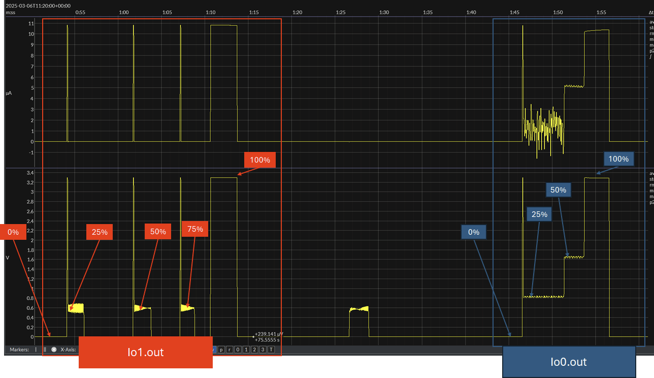
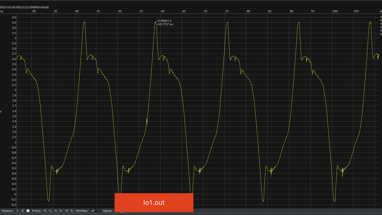
Wanted to show the chart with the L298N connected, showing how io1.out cuts out. I recognize that, by default, the 'fan' blip time is set to B0.1. Can test later without that.
-
[3.6.0-rc.1] EXP1HCL V1.0a io1.out PWM Issuesposted in Beta Firmware
EXP1HCL V1.0a - purchased January 2024, but unused until now. I found this thread that may be similar: https://forum.duet3d.com/topic/36048/exp1hcl-50-io1-out-pwm-control-issue?_=1741220546477
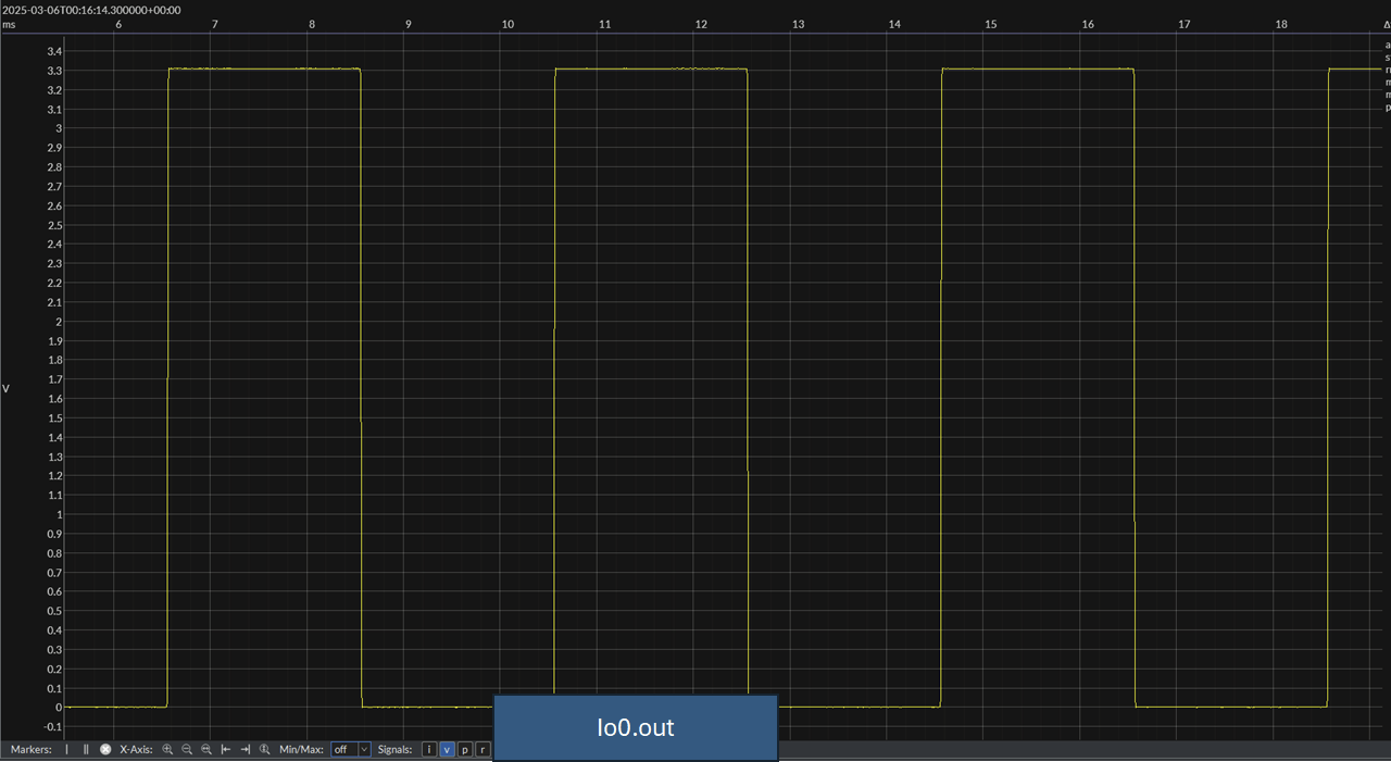
Given - docs state both io0.out and io1.out are PWM capable. Note that the configuration for a fan is only for testing via the fan slider, and no fans are actually connected to these outputs.
M950 F8 C"123.io0.out"
M106 P8 C"Dir1"

M950 F9 C"123.io1.out"
M106 P9 C"Dir2"
io0.out outputs PWM as expected, however io1.out gives a bizarre waveform at 1-99% or so 'fan speed', until at 100% you get 3.3v. Note that graphs below are with no load on the outputs. Issue is also present for the intended use case (w/ a L298), though it seems I only get a blip on io1.out. Percentages represent the fan slider percent.
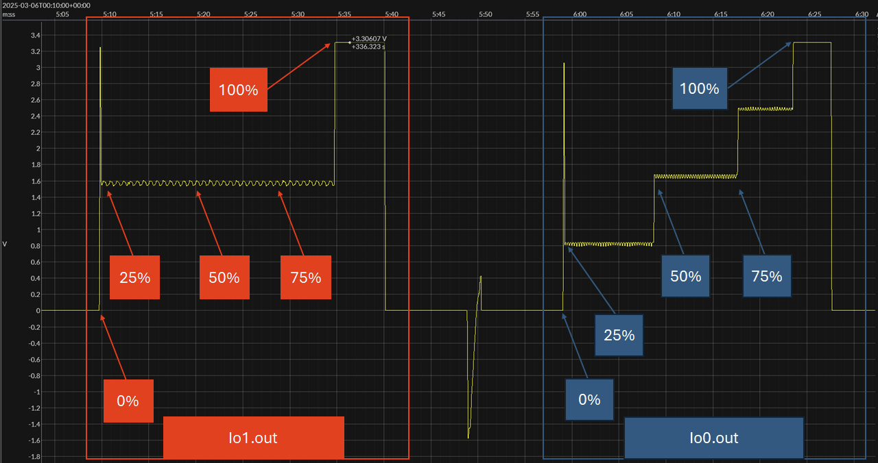
io1.out - zoomed in some

io0.out - zoomed in some

M122
M122
=== Diagnostics ===
RepRapFirmware for Duet 3 MB6HC version 3.6.0-rc.1 (2025-02-28 15:00:13) running on Duet 3 MB6HC v1.02 or 1.02a (standalone mode)
Board ID: 08DJM-9P63L-DJ3S0-7J1DD-3SN6L-9VMMA
Used output buffers: 7 of 40 (37 max)
=== RTOS ===
Static ram: 137420
Dynamic ram: 130932 of which 0 recycled
Never used RAM 75704, free system stack 186 words
Tasks: NETWORK(1,ready,30.4%,135) ETHERNET(5,nWait 7,0.1%,400) HEAT(3,nWait 6,0.0%,350) Move(4,nWait 6,0.0%,333) TMC(4,nWait 6,3.1%,375) CanReceiv(6,nWait 1,0.0%,796) CanSender(5,nWait 7,0.0%,334) CanClock(7,delaying,0.0%,350) MAIN(1,running,66.1%,103) IDLE(0,ready,0.2%,29) USBD(3,blocked,0.0%,144), total 100.0%
Owned mutexes: LwipCore(NETWORK)
=== Platform ===
Last reset 00:11:53 ago, cause: software
Last software reset at 2025-03-05 19:08, reason: User, Gcodes spinning, available RAM 75656, slot 2
Software reset code 0x0003 HFSR 0x00000000 CFSR 0x00000000 ICSR 0x00400000 BFAR 0x00000000 SP 0x00000000 Task MAIN Freestk 0 n/a
=== Storage ===
Free file entries: 20
SD card 0 detected, interface speed: 25.0MBytes/sec
SD card longest read time 3.2ms, write time 59.1ms, max retries 0
=== Move ===
Segments created 0, maxWait 0ms, bed comp in use: none, height map offset 0.000, hiccups added 0/0 (0.00/0.00ms), max steps late 0, ebfmin 0.00, ebfmax 0.00
Pos req/act/dcf: 0.00/0/0.00 0.00/0/0.00 0.00/0/0.00 0.00/0/0.00
No step interrupt scheduled
Driver 0: standstill, SG min n/a, mspos 8, reads 50341, writes 17 timeouts 0
Driver 1: standstill, SG min n/a, mspos 8, reads 50341, writes 17 timeouts 0
Driver 2: standstill, SG min n/a, mspos 8, reads 50341, writes 17 timeouts 0
Driver 3: standstill, SG min n/a, mspos 8, reads 50341, writes 17 timeouts 0
Driver 4: standstill, SG min n/a, mspos 8, reads 50341, writes 17 timeouts 0
Driver 5: standstill, SG min n/a, mspos 8, reads 50341, writes 17 timeouts 0
Phase step loop runtime (us): min=0, max=86, frequency (Hz): min=1467, max=3125
=== Heat ===
Bed heaters 0 -1 -1 -1 -1 -1 -1 -1 -1 -1 -1 -1, chamber heaters -1 -1 -1 -1 -1 -1 -1 -1, ordering errs 0
=== GCodes ===
Movement locks held by null, null
HTTP is idle in state(s) 0
Telnet is idle in state(s) 0
File is idle in state(s) 0
USB is idle in state(s) 0
Aux is idle in state(s) 0
Trigger is idle in state(s) 0
Queue is idle in state(s) 0
LCD is idle in state(s) 0
SBC is idle in state(s) 0
Daemon is idle in state(s) 0
Aux2 is idle in state(s) 0
Autopause is idle in state(s) 0
File2 is idle in state(s) 0
Queue2 is idle in state(s) 0
=== Filament sensors ===
Driver 31: no data received, errs: frame 0 parity 0 ovrun 0 pol 0 ovdue 0
=== CAN ===
Messages queued 6243, received 8566, lost 0, ignored 0, errs 0, boc 0
Longest wait 1ms for reply type 6062, peak Tx sync delay 379, free buffers 50 (min 49), ts 3382/3381/0
Tx timeouts 0,0,0,0,0,0
=== Network ===
Slowest loop: 115.45ms; fastest: 0.03ms
Responder states: MQTT(0) HTTP(0) HTTP(2) HTTP(0) HTTP(0) HTTP(0) HTTP(0) FTP(0) Telnet(0) Telnet(0)
HTTP sessions: 1 of 8
=== Multicast handler ===
Responder is inactive, messages received 0, responses 0
= Ethernet =
Interface state: active
Error counts: 0 0 0 0 0 0
Socket states: 6 4 2 2 2 0 0 0 0
=== WiFi ===
Interface state: disabled
Module is disabled
Failed messages: pending 0, notrdy 0, noresp 0
Socket states: 0 0 0 0 0 0 0 0
M122 B123
M122 B123 Diagnostics for board 123: Duet EXP1HCL rev 1.0a or earlier firmware version 3.6.0-rc.1 (2025-02-28 15:01:26) Bootloader ID: SAME5x bootloader version 2.4 (2021-12-10) All averaging filters OK Never used RAM 81372, free system stack 178 words Tasks: Move(3,nWait 7,0.0%,178) CLSend(3,nWait 6,0.0%,149) TMC(2,nWait 6,26.0%,349) HEAT(2,nWait 6,0.0%,130) CanAsync(5,nWait 4,0.0%,70) CanRecv(3,nWait 1,0.0%,74) CanClock(5,nWait 1,0.0%,64) MAIN(1,running,73.2%,409) IDLE(0,ready,0.0%,29) AIN(2,nWait 2,0.8%,255), total 100.0% Owned mutexes: Last reset 00:12:32 ago, cause: software Last software reset data not available Moves scheduled 0, hiccups 0 (0.00/0.00ms), segs 0, step errors 0 (types 0x0), maxLate 0 maxPrep 0, ebfmin 0.00 max 0.00 Phase step loop runtime (us): min=0, max=104, frequency (Hz): min=0, max=39473 Peak sync jitter -6/8, peak Rx sync delay 184, resyncs 0/0, next timer interrupt due in 23 ticks, enabled, next step interrupt due in 3730453500 ticks, disabled VIN voltage: min 24.2, current 24.2, max 24.3 V12 voltage: min 12.0, current 12.1, max 12.1 MCU temperature: min 33.5C, current 34.3C, max Driver 0: pos 0, 80.0 steps/mm, standstill, SG min n/a, mspos 8, reads 36573, writes 11 timeouts 0 Last sensors broadcast 0x00000000 found 0 177 ticks ago, 0 ordering errs, loop time 0 CAN messages queued 9060, send timeouts 0, received 6593, lost 0, ignored 0, errs 0, boc 0, free buffers 38, min 38, error reg 0 dup 0, oos 0/0/0/0, rxMotionDelay 0 Closed loop driver 0 mode: open loop, pre-error threshold: 2.00, error threshold: 4.00, encoder type none Accelerometer: none I2C bus errors 12, naks 0, contentions 0, other errors 0 -
RE: Z wont go to the corect dept when printing.posted in Tuning and tweaking
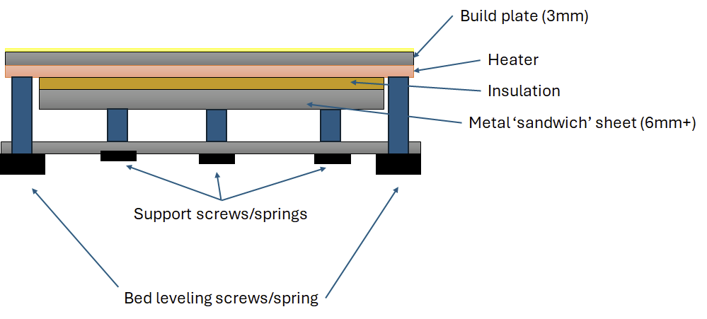
@Snippy 20x20 grid is likely overkill. Based on the 3mm thickness, you could probably do some calculations (or find a calculator) to derive a linear spacing of supports driven by what you would consider a reasonable bed deflection value - could start with .1mm. Unfortunately 3mm is really, really thin, especially at that size.
Is your bed heater a silicone type?
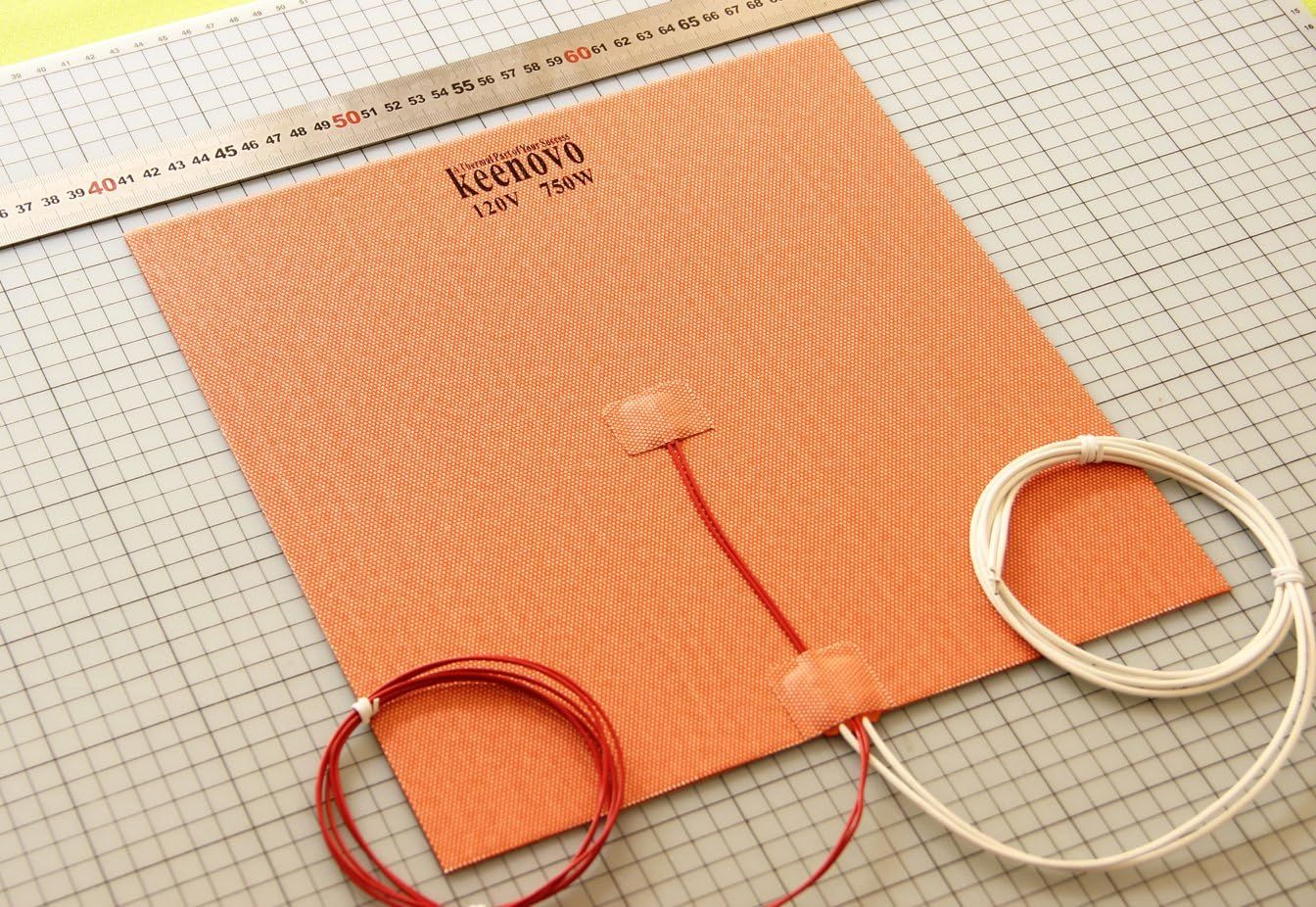
Depending on what type of rubber tips you have in mind, I'd be concerned about their temperature rating, plus potential long term wear on the underside of the bed. What would be better is having a thicker sheet sandwiched below the bed heater. Not the best idea (or best sketch) buy maybe can mitigate the sagging bed.
-
RE: Z wont go to the corect dept when printing.posted in Tuning and tweaking
@Snippy said in Z wont go to the corect dept when printing.:
M208 X0:400 Y0:400 Z0:220 ; set minimum and maximum axis limits
This, combined with what @droftarts is saying about where you're setting your Z datum , is why you're not seeing compensation occur in the negative Z direction. You could allow for negative moves in the Z direction, such as
M208 Z-5:220and/or adjust where you're setting the Z datum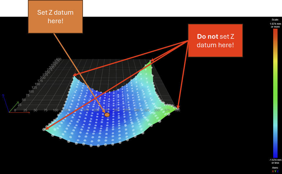
For a 410mmx410mm bed, a thickness of 3mm without supporting the underside will result in poor dimension accuracy for your parts, as the bed will naturally sag in the middle. 1.6mm is substantial. I would recommend a thicker bed in the range of 10mm to 12mm, or some adjustable screws to help support the center of the bed.
-
RE: Z wont go to the corect dept when printing.posted in Tuning and tweaking
@Snippy Can you post your config.g file? Specifically looking for your M208 line based on the following quote:
@Snippy said in Z wont go to the corect dept when printing.:
My problem is that after get a height map from G29 the map does nothing to compensate when printing, Z does not moove in -Z only in Z+.
Edit: Your bed does not look healthy lol.
-
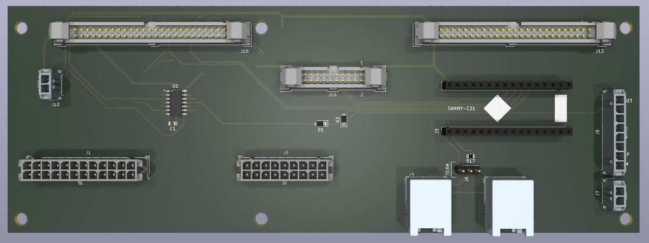
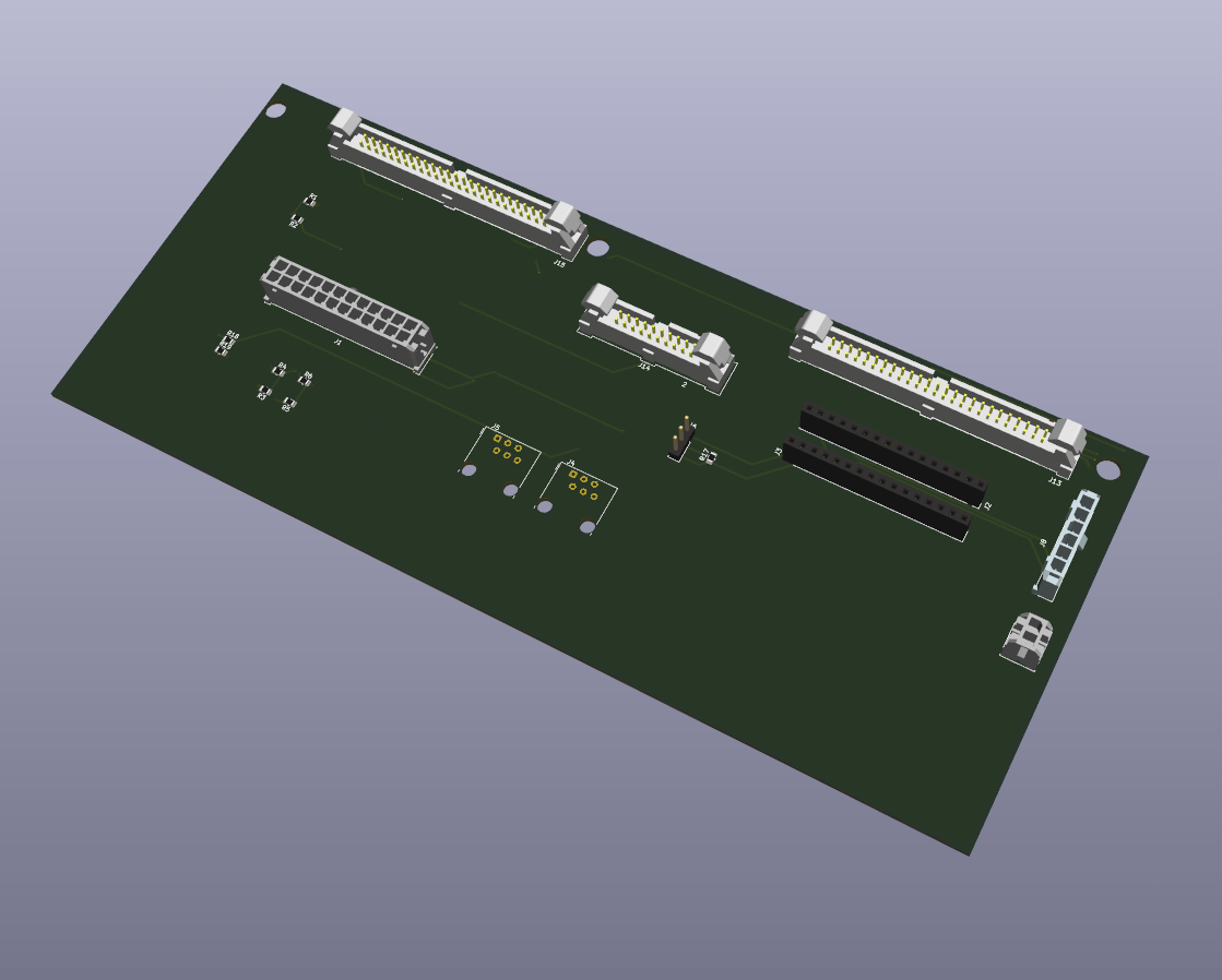
RE: 'DuePrint' with a Duet 3 6HC - Stratasys Dimension Conversionposted in My Duet controlled machine
Getting closer with the adapter board:
One Item I've just started to look into, but haven't yet worked out is enabling the PDB without the SBC attached. @AJ-Quick unsure if you ran into any issues disconnecting the SBC power cable (4-pin Molex 8981 connector) - initially on power up all power LED status lights are on, and the 5V/12V power supply is outputting voltage. After a few seconds, the 5V/12V power supply cycles between on and off. I wonder if the 5V/12V power supply has some sort of minimum load?
I believe I've got the correct set of pins on the PDB getting power, simply having only the power connector connected to the SBC (no hard drive I/O or power, no display) allows it to power on correctly.
Video of issue: https://www.youtube.com/watch?v=GKUwO8F4w1w
Edit: Power supply in question is P/N LPT62, reading the datasheet, minimum loads are .7A on the 5V line, and .3A on the 12V line.
-
RE: 'DuePrint' with a Duet 3 6HC - Stratasys Dimension Conversionposted in My Duet controlled machine
@AJ-Quick Once again, my sincerest thanks for your previous work!
Once the interface board is in a useable state, I would be happy to send you one!
To your point on the motors, that is the only part of the Duet that’s likely used to its potential, as for the most part we’re just using RRF and the board to control I/O, as the PDB does all the heavy lifting for things like heaters and whatnot. The 6x stepper drivers on the Duet are overkill (we only use three of them, and off the top of my head the motors are rated at 2A, 2.8A, and 2.8A for X, Y, and Z), and we’re running the board off half its rated voltage. The Geckodrive is also overrated for the application, it could be used for much larger motors, but instead we’re using it simply for control signals.
A custom board (or possibly even an appropriate evaluation kit) could possibly be enough to support all the needed I/O channels. Of course then you’d have to solve the motor control issue, though perhaps that results in using a Duet 3HC via CAN-FD.
Not a problem I’m prepared to solve, happy enough to use the 6HC!
-
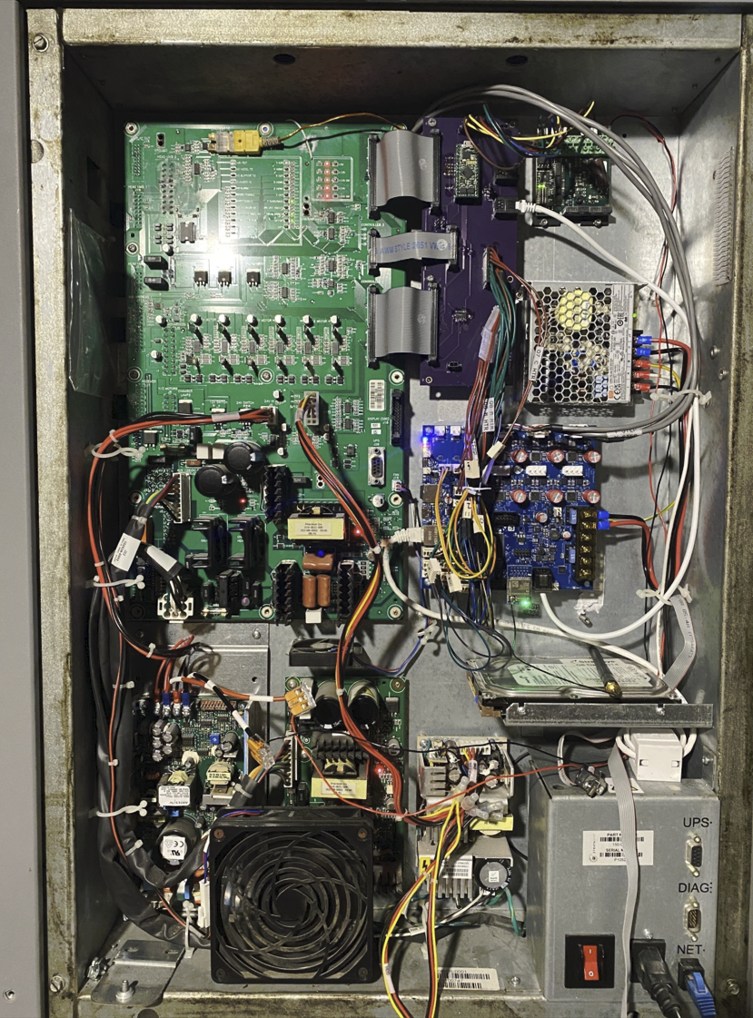
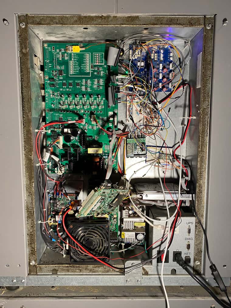
'DuePrint' with a Duet 3 6HC - Stratasys Dimension Conversionposted in My Duet controlled machine
First of all, major thanks to @AJ-Quick, @drphil3d, @Archeantus and @Pete_A for their previous posts regarding converting the Stratasys Dimension, Fortus (250), and uPrint models over to the Duet ecosystem, as I doubt I would have been able to get as far as I have without their previous research, experimentation, and engineering. A great thread here, resulting in this awesome Hackaday post detailing @Archeantus 's fully reversible conversion.
My twist on this was to instead of using the Duet 2 product line, attempt the conversion with a Duet 3 6HC and Sammy-C21.
The fully reversible approach is quite great because it's likely the easiest way to convert one of these machines, as the existing motion, sensing, and extruding hardware is solid. Other approaches, in my opinion, are implemented by swapping in substandard hardware, and at greater time & expense.
Ultimate goal is to have an adapter board that would simplify the conversion process (notional setup below); now that the motors and the bulk of the inputs/outputs can be managed, I think I can move on to refining the board.
For now though, the electronics enclosure is very much a living, breathing organism

What is the current status?
Able to move the motors, home the axes, power on the heaters, and print!What are the next major next steps?
Tool change, probe, nozzle cleaning macros need to be fully fleshed out. Would like to integrate the 9x limit/position switches into the configuration as best I can (X, Y, Z home, X, Y, Z end of travel, Z probe, Model toggle, Support Toggle)What won't I be tackling in this project:
- Will not attempt to integrate the existing front user interface/screen. Instead, I'll likely pull that module out, and install a PI and touchscreen (do not intend to run the Duet with the SBC attached however)
What I haven't yet tested:
- Anything with the material bay. The user who posted the Hackaday project did some initial integration efforts, once I'm confident with the bulk of the printing portion of the printer, I'll look into the material bay control (less to use the material spools, but more to help loading in filament).
- Have not tested thermostat outputs as inputs on the Duet, but that should be low effort.
Something that surprised you?
I had previously experimented with driving the Geckodrive G320X with a Duet 2/ Duex, but I was genuinely surprised I was immediately able to get it moving as required with the Sammy-C21 STEP/DIR pins- was expecting to have to do a lot more fiddling!Motor Control:
- Bypass the Stratasys PDB for the X, Y, and Z motors, instead wire directly to them from the 6HC
- Use the Sammy-C21 (default firmware build) to interface with a Geckodrive G320x via STEP/DIR. The Geckodrive interfaces with the PDB to control the DC motor for the extruder (the G320x actually doesn't directly connect to the motor armatures, rather it goes through to a L298P full bridge driver. In this application, the G320X is mainly used just to gain closed loop control of the motor).
- Instead of a Sammy-C21, a Duet 1XD could most likely be used.
Temperature Sensing:
There are three temperature sensors to interface with, all three are K-Type thermocouples. While the chamber thermocouple terminates inside the electronics enclosure, the two hotend thermocouples are terminated and processed in the print head. From the PDB the processed analog voltage spans from 0v (low temp) to 5v (high temp). To be read by the Duet temperature inputs, the analog voltages go through voltage dividers to get down to scale from 0v to 3.3v.I validated the temperature range by soldering a few wires onto the existing Stratasys Control board, and running a print (with the original control board, SBC, etc), logging the values via a Labjack T7 DAQ. At the same time, I fed the analog voltages to the Duet, finding that ~1v was applies to the sensor inputs, biasing the temperature high. Once I made that discovery it was pretty straightforward to correct my M308 B and C values.
Limit Switches (Optical Switches):
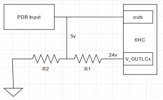
I fed the limit switch outputs directly from the PDB to the 6HC inputs (5v signal, 6HC's inputs are 30v tolerant).Enabling Head Blower Fan, LED Lights, etc:
A few ways of doing this - ultimately you need to send 5v to the PDB. To use the I/O headers, I used SN74AHCT125N level shifters to take 3v to 5v.To use the low current outputs, this works well:
Plenty more to work on, but for now, proof of life:
https://www.youtube.com/watch?v=rRLwZSXlzxI