Duet3D Logo Duet3D
    • Tags
    • Documentation
    • Order
    • Register
    • Login
    1. Home
    2. sebkritikel
    3. Best
    • Profile
    • Following 0
    • Followers 1
    • Topics 10
    • Posts 371
    • Best 108
    • Controversial 0
    • Groups 0

    Best posts made by sebkritikel

    • New Large Format IDEX Printer Project

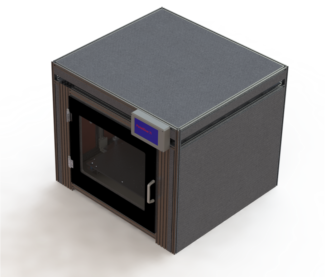
      I'm pleased to share a personal project of mine, where the initial design started in late 2018, and purchasing started in March of 2019. By no means is this complete, but I'm at a point where I'm excited to share the progress I have made so far.

      Some background - My first real experience with 3D printing was in 2017 at the office; we had a Stratasys Dimension 1200es BST that wasn’t getting much use. I started printing practically anything I could think of, starting with a small hand tool, and progressing to much larger and more sophisticated designs. In early 2018 I got the go-ahead to propose search for a new 3D printer model that we would buy two of – because more is better, right? At that point I realized both the age of the Stratasys machine, as well as the wealth of hardware and software options for printers available at the time.

      We opted to go with two BCN3D Sigmax printers – dual extrusion was a must, the IDEX technology had some potential uses, and the large bed width was attractive. I spent quite a bit of time learning how to effectively operate those machines (they are surprisingly a lot of work!); later I picked up a used Davinci 1.0 and flashed it with Repetier, built a MPCNC, and eventually the Stratasys went belly-up and made its way home with me.

      IMG_7489.JPG
      IMG_7491.JPG
      IMG_7490.JPG
      render2.png
      render3.png

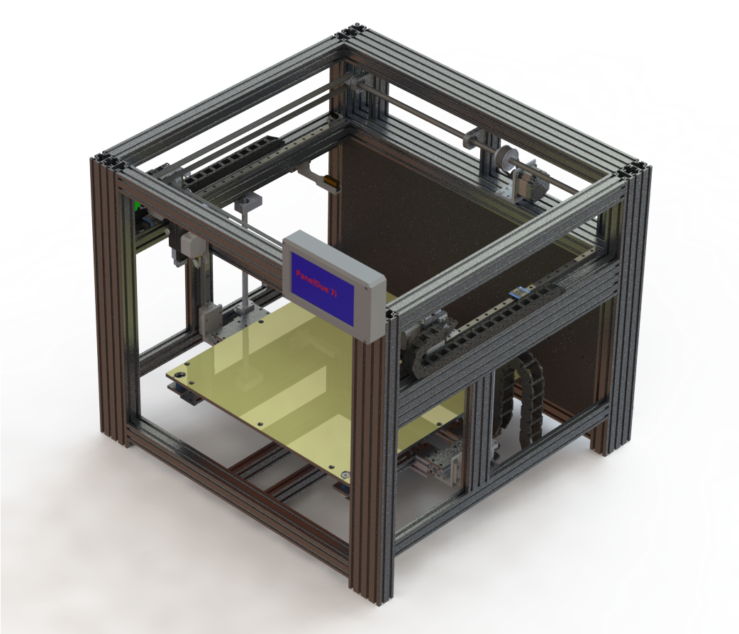
      My initial design objectives were to have a machine that…

      • Has a rigid frame
      • Has a limited number of 3D printed components
      • Has an enclosed and heated chamber
      • Has a large print area
      • Is capable of printing high temperature thermoplastics
      • Is capable of dual extrusion
      • Is capable of fast travel speeds with reasonable accelerations

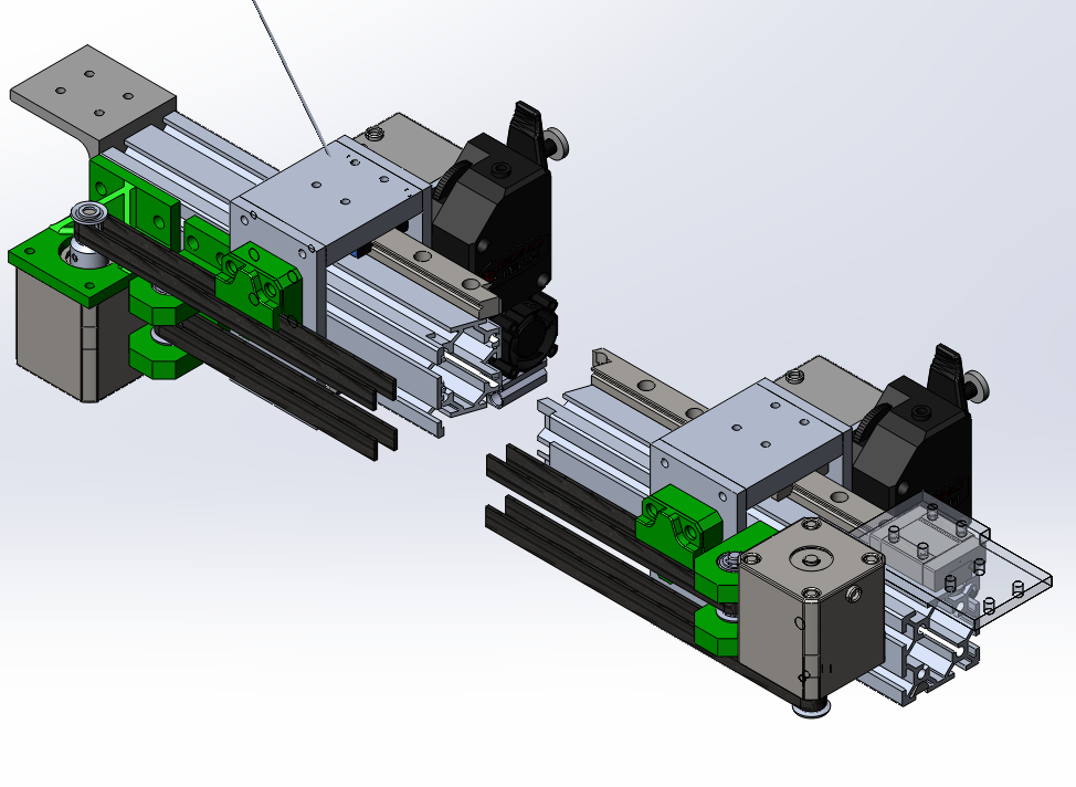
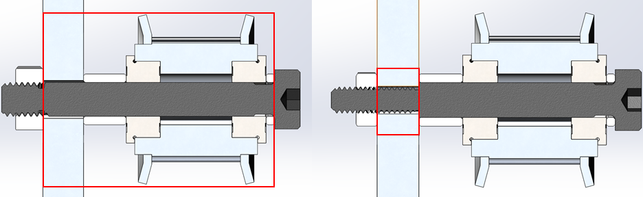
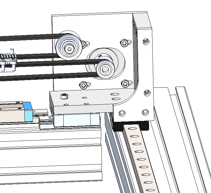
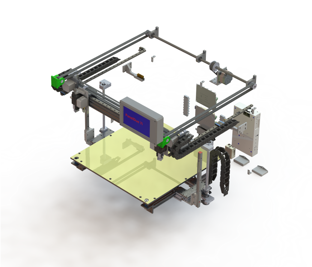
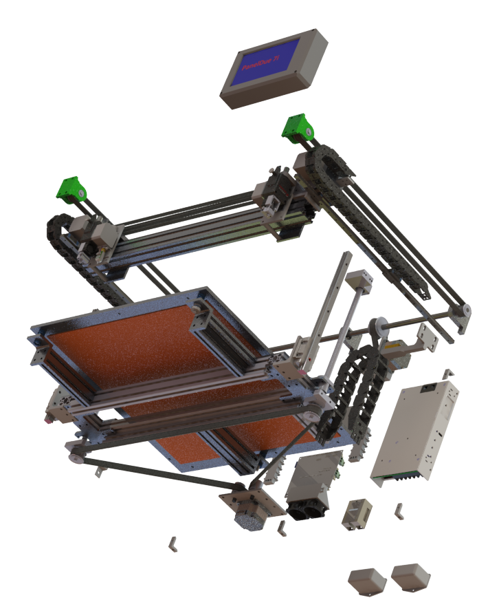
      To start the design, I purchased two Rexroth ballscrews and 3x sets of IKO LWL12B 500mm rails with two ML12 each, sizing the frame to these components. Later on I purchased two LWHT15 200mm rails with a single carriage each for use with the ballscrews for the Z-Axis.

      Other design and component decisions:
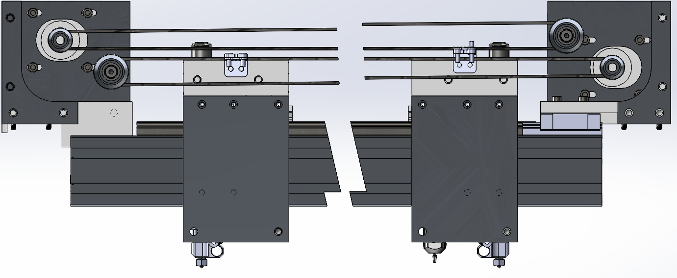
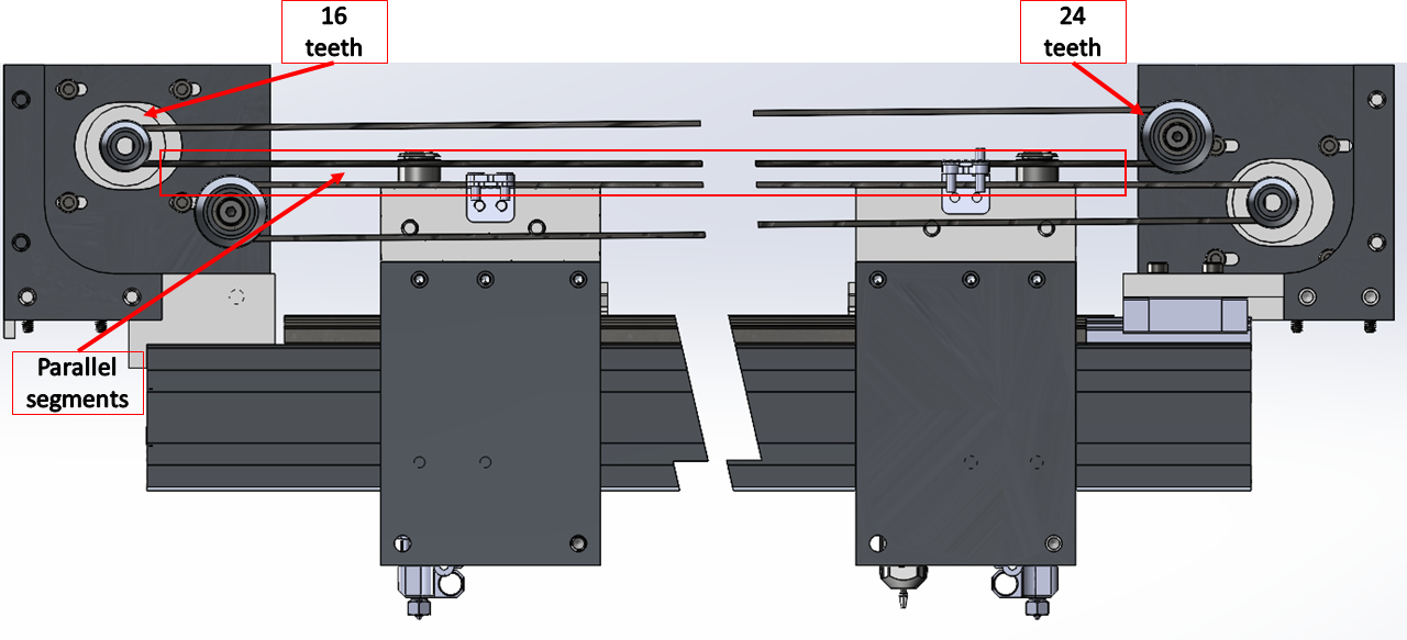
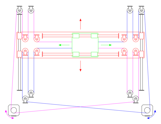
      I wanted to utilize the Gates GT3 series of belts and compatible pulleys

      • For the Y-axis I selected 3mm belt pitch, 15mm belt width
      • For the X/U-axis, I selected 2mm belt pitch, 9mm belt width

      I wanted to balance speed and resolution

      • 16x microstepping, managing to achieve 100steps/mm in the X/U axis, 96steps/mm in the Y axis
      • Y axis is geared down with a 2.25:1 gear ratio to compensate for the heavier axis
      • X, U, and Y axis run at 300mm/s max speeds and 4000mm/s^2 acceleration

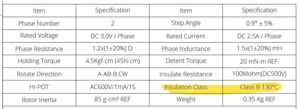
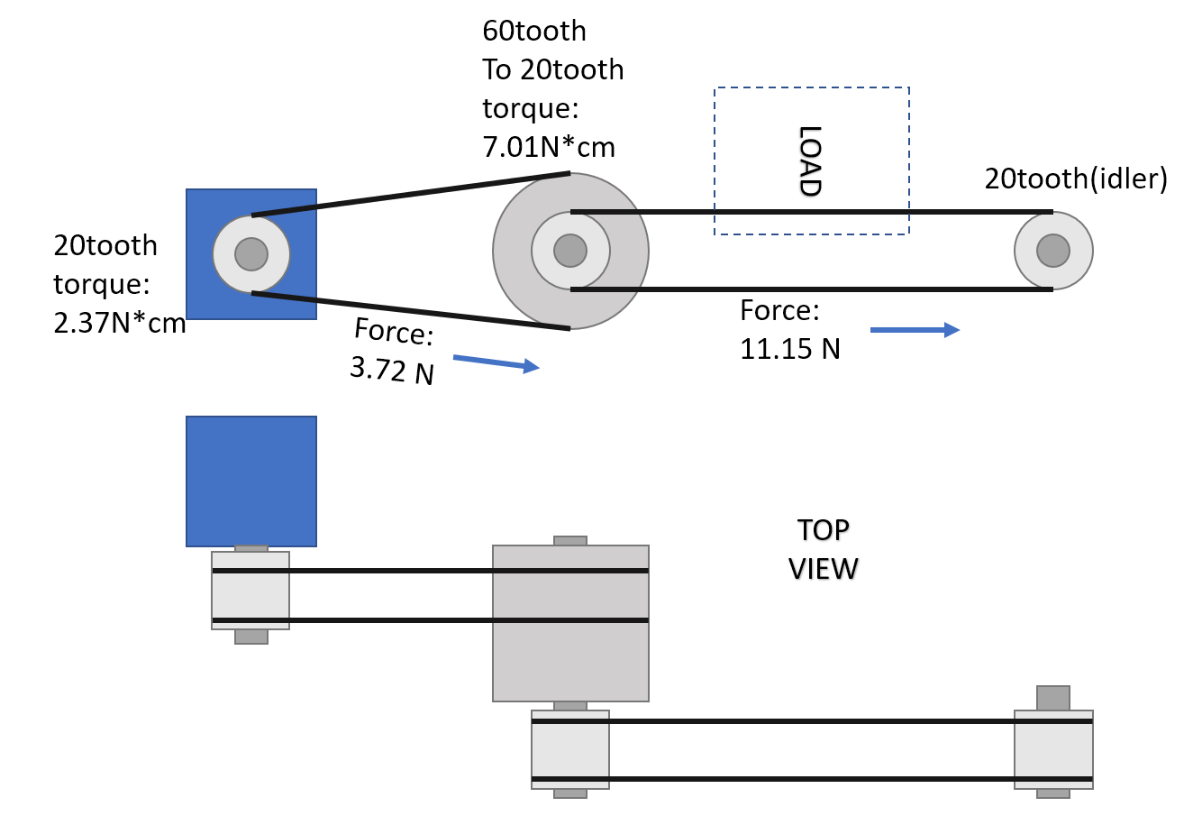
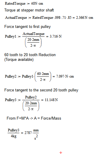
      For the Y-axis and Z-axis, stepper motors are NEMA 23

      • Oriental Motor PKP264D28AA2, .74 N*m, 2.8 A/phase, 1.5mH/phase
      • Set to 2.4A in config.g
      • Run super cool, barely feel warm to the touch

      X and U axis use NEMA 17

      • Oriental Motor PKP244D23A2, .48N*m, 2.3 A/phase, 1.9mH/phase
      • Set to 1.8A in config.g
      • These run quite a bit warmer than the NEMA 23s

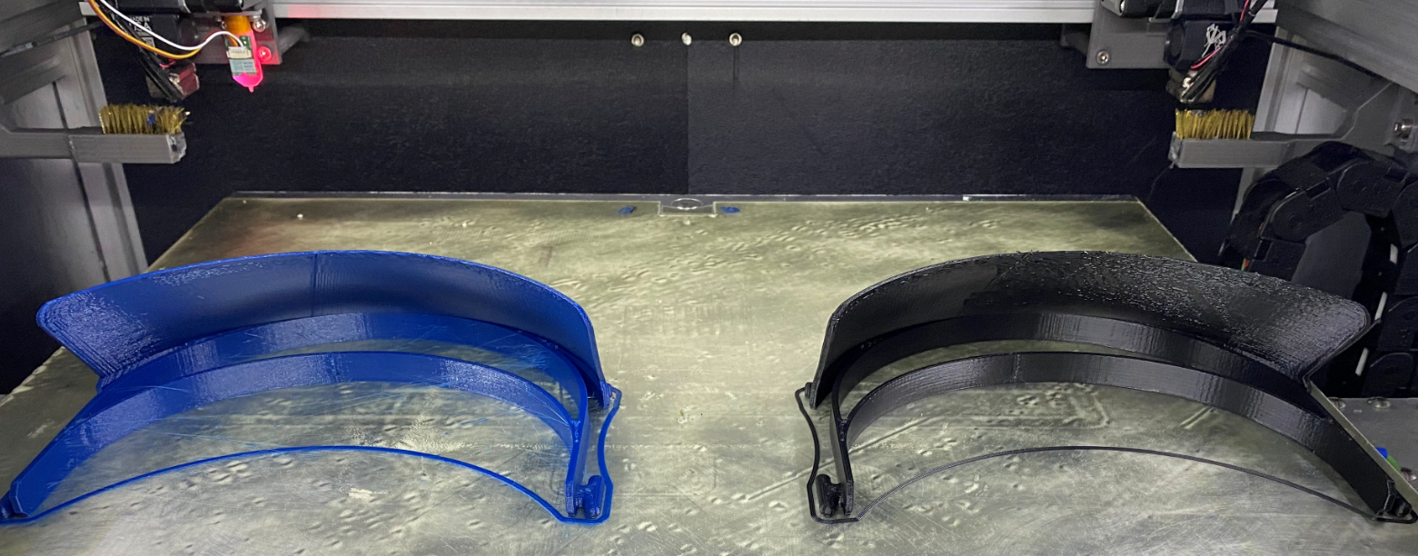
      Slice Engineering Mosquito and Mosquito Magnum for hotends

      • Various nozzles (P3D, E3D NozzleX, Slice Vanadium
      • Slice thermistors and heaters
      • 12V Sunon fans

      5/16” ATP 5 plate, 1000W Keenovo heater, SDF DF240S thermal cutoff (200°C holding temperature)

      • TCO holding temperature may be a little high, but Keenovo recommended a maximum operating temperature of 204°C based on the 3M adhesive rating.
      • Three-point bed leveling with probing
      • Initially looked at a kinematic bed solution but opted for a fixed countersunk screw/spring combo, with two slotted countersinks sized and positioned to account for thermal expansion.

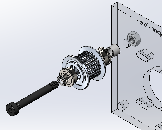
      Bondtech BMG-M extruders

      IDEX

      • I do enjoy the IDEX technology on the BCN3D printers but wanted something a bit more structurally sound. Mechanically, lots of inspiration taken from the Stratasys Dimension 1200es.

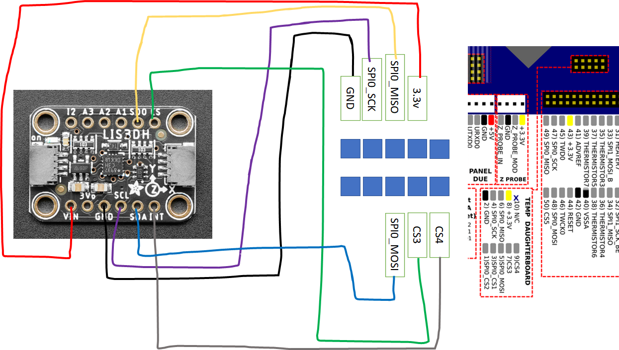
      Duet controller board(s) - Duet 2 Wifi, Duex5, PanelDue 7i

      Snap action homing switches for X, U, and Y

      • These have moved quite a bit as the design has evolved, I’m not happy with how they are mounted at the moment
      • Had a homing “oopsie” where the U assembly crashed into the X carriage, actually moving the switch mounting block, and messing up my calibration!

      Right now I’m looking at a print volume (single extruder) of 420mm x 450mm (475mm Y travel) x 210mm, losing ~100mm (to ~320mm) on the X and U axis for dual extrusion (lesson learned there!).

      The project so far has been a blast, with many lessons learned along the way. The X-U axis has by far been the most challenging to build and design, I’m on the second major iteration and I’m still not entirely pleased, although I am getting satisfactory print results. As this is my first printer design and build, it was challenging to prioritize assembly design priorities. With this project, despite having a good idea of the components I wanted on each hotend assembly, it was the last item I designed and built up – ends up my build plate was a bit too big, leaving me little room to have nozzle wipe stations, purge buckets, etc. On future projects I for sure have a better idea of what assemblies to prioritize, making further decisions based on the size and function of said assemblies.

      While working on this project, I did not initially intend to share the design files, however because of all that I learned from the fantastic content and individuals on this community and others, I figured I should give back and contribute this project.

      https://drive.google.com/drive/folders/12TOxGG-kKjuYwNuwhYpwor9TGhdfy2mg?usp=sharing

      The Google Drive link contains a Solidworks (19-20) pack-and-go, as well as assembly parasolids (.x_t) and IGS files. A (very!) rough BOM and various images and videos of my progress are also available.

      How have I done so far?

      • Has a rigid frame - definitely nailed this one! Almost entirely end tapped extrusions with fasteners + access hole
      • Has a limited number of 3D printed components - making progress, but not quite done. Y axis bearing holders, most of the hotend carriage assembly is still 3D printed
      • Has an enclosed and heated chamber - making progress on enclosure, have not installed+tested active chamber heating (excluding built plate)
      • Has a large print area - pretty satisfied
      • Is capable of printing high temperature thermoplastics - goes hand in hand with the heated enclosure, no issue with extruding 9085 PEI, but I have not tested an actual PEI print (the volume above the build plate stabilizing at 50°C without being fully enclosed, which is pretty neat, but not enough for PEI)
      • Is capable of dual extrusion - accomplished
      • Is capable of fast travel speeds with reasonable accelerations - accomplished

      Many thanks to Slice Engineering, PrintedSolid, and Filastruder ( @elmoret ) for fast shipping, excellent communication, and great customer service when it was needed, as well as to the Duet team for a fantastic product.

      render1.png
      render4.png
      IMG_7493.JPG

      posted in My Duet controlled machine idex bondtech nema23 enclosure
      sebkritikelundefined
      sebkritikel
    • RE: IDEX anyone?

      @BlueDust said in IDEX anyone?:

      I am thinking about building an IDEX printer as a 2nd printer. Few questions...
      Could I use a filament sensor on each extruder?
      Using a Duet2, would I also need a Duex5 to run an IDEX?
      Is best practice installing a bed level sensor on both hotends?

      Are there any considerations or limitations I should be aware of in regards to building an IDEX printer and it's use?

      Thanks!

      I'm running an IDEX, and I do enjoy the flexibility of it. Some advantages when compared to single extrusion - multi material, mirror/ditto print, and different diameter nozzles in the same print (walls vs infill, etc).

      You will need an expansion board when using a Duet2, I'm using a Duex5, but I think you can get away with a Duex2.
      I only have a bed leveling sensor on one hotend, I calibrate the second within the config.g to line up with the first hotend.

      Like any multi extrusion setup, it gets expensive. The mechanics and design considerations of the gantry holding the two hotends gets a little more complex, and you have additional hardware to sling around. Whenever you change your nozzle setup, you will need to re calibrate both hotends, as there are minute differences in nozzles.

      posted in General Discussion
      sebkritikelundefined
      sebkritikel
    • RE: Many issues after upgrading to 3.0 RC-12

      @TheBasedDoge said in Many issues after upgrading to 3.0 RC-12:

      Ok, here it is. thank you!

      ; Configuration file for Duet WiFi (firmware version 3)
      ; executed by the firmware on start-up
      ;
      ; generated by RepRapFirmware Configuration Tool v2.1.8 on Sun May 10 2020 13:55:08 GMT-0400 (Eastern Daylight Time)
      ; Axis Limits
      M208 X0 Y0 Z0 S1                                       ; set axis minima
      M208 X300 Y0 Z0 S0                                     ; set axis maxima
      

      M208 X300 Y0 Z0 S0 ; set axis maxima

      That looks like a mistake - Y300 right??

      posted in Firmware installation
      sebkritikelundefined
      sebkritikel
    • RE: Duet3D announces new tool board at FormNext

      @Surgikill Most stepper motors used by 3D printing enthusiasts are built using 'Class B' insulation for the motor windings. For 'Class B', the max allowable winding insulation temperature is 130°C, which often yields a max motor ambient temperature of 40-50°C (not stepper casement temperature).

      http://www.drivesandautomation.co.uk/useful-information/nema-insulation-classes/

      Example motor with specs on insulation, thermal rise, etc
      https://catalog.orientalmotor.com/item/2-phase-bipolar-stepper-motors/42mm-pkp-series-2-phase-bipolar-stepper-motors/pkp244d08a2

      Most of us skirt by this 'max temperature' limitation by running steppers at 85% or so of the rated current, that gives some margin for an elevated ambient temperature. Running with an ambient temperature higher than the spec'd motor ambient could result in reduce service life for the motor. Ends up most of us ignore what 'Class B' insulation means, or simply don't know (I have been ignoring it, been running ambients in the 60-70°C on my motors 🤠 )

      Without looking at a datasheet... the roto motor likely has 'Class B' insulation.

      Speaking of datasheets, a lot of steppers used in printers seen here don't go into the detail manufacturer's like Oriental Motor use on their datasheets (example snippet from a popular stepper seen here):
      197c7ff6-e980-4b5b-af54-73e013fb573a-image.png

      If you read the specs above, and don't further research what 'Class B' means, you might assume the motor running at 130°C is fine... and by running at 130°C, one might think thats the easily observable casement temperature (they do get hot!).

      With extruder motors, its often recommended to run them at a significantly reduced current (at least when they were using smaller NEMA17 motors) for two reasons:

      1. The torque at full current was much greater than what was needed for extrusion force
      2. The casement thermal rise at full (or 85%) current could soften the filament, depending on how the filament drive was connected to the stepper)

      Its possible that, while the roto motor uses 'Class B' insulation, it doesn't need to run at rated current, meaning theres higher margin for ambient temperature (maybe, a good amount of conjecture on my part of the requirements of the roto motor 🙂 )

      As far as that LDO pancake stepper, LDO has been making a series of high temperature motors for the enthusiast community using higher rated winding insulation.

      posted in General Discussion
      sebkritikelundefined
      sebkritikel
    • RE: Pressure advance limits?

      @gnydick said in Pressure advance limits?:

      @engikeneer thanks. Yes, I'm aware of the distinction. From my pictures, you can see the ghosting only happens after sharp feature changes. That's why I believe it's PA.

      I may be missing something, but I don't believe its PA, and I do believe it is DAA, M593. Have you configured M593?

      I think you're conflating a PA "fix" at 2000 mm/s^2 when really the system doesn't create ringing at 2000mm/s^2.

      I would recommend running your same test, but with an appropriate value of M593 configured. Verify the speed at which your outer perimeters are set to (stock print speed doesn't always equal the perimeter speed... make sure you double check), and divide that by the "peaks" of the ghosting ripples.

      posted in Tuning and tweaking
      sebkritikelundefined
      sebkritikel
    • RE: Danal's passing

      I am saddened by the news. While I had limited direct interaction with Danal, his posts were always insightful and his projects an inspiration. He will certainly be missed in all the communities he participated in.

      posted in Off Topic
      sebkritikelundefined
      sebkritikel
    • RE: Delta stepper upgrade - advice welcome

      @Nxt-1 said in Delta stepper upgrade - advice welcome:

      @sebkritikel Thank you for the suggestions. Do you have any experience with either of the motors you suggested?

      I have also found these from the same supplier:

      PKP266MD28BA

      • Rated current: 2.80 A
      • Holding torque: 1.32 Nm
      • Inductance: 3.90 mH
      • Rotor inertia: 290.0 gcm²
        (6.35 mm shaft)

      PKP266MD28B2

      • Rated current: 2.80 A
      • Holding torque: 1.40 Nm
      • Inductance: 3.00 mH
      • Rotor inertia: 310.5 gcm²
        (8 mm shaft)

      These see to be the longer versions of the ones you linked (54 mm vs 39 mm)

      I don't have any experience with those models, however I do use two PKP264D28AA2 NEMA23s (2.8A/phase, 1.8°, 39mm, 74Ncm, 1.5mH inductance) on my printer, and they are fantastic.

      I see you're trying to hit 200steps/mm with a 2mm pitch belt @ 16teeth on a pulley... I don't know how realistic it will be to find a pulley with 16 2mm teeth, and 6.35mm or greater shaft bore

      Excerpt from Misumi's 2mm PowerGrip® GT®3 catalog listing

      34e6bb57-fcf4-4aa5-9b5f-6e54ba6c6e75-image.png

      posted in General Discussion
      sebkritikelundefined
      sebkritikel
    • RE: Tips to mitigate vertical artifacting Duet 2 Wifi

      @bot said in Tips to mitigate vertical artifacting Duet 2 Wifi:

      Well, I wasn't able to find any ready-to-go off-the-shelf idlers from Misumi (that are more than 5 or 6 mm), but I've always wanted to try using one of their customizable pulleys for idlers: See info here.

      You can choose a wide range of sizes of pulley there, and you can get stepped holes made which should allow for easy placement of bearings. They have a variety of options and you can have the stepped hole sized how you wish. See:

      snip

      [Edit: this photo is slightly misleading, there are more options to configure to get a full part number. Still playing around with it 😛 ]

      I've done that on my machine, and it works quite well (albeit the assembly stackup can get pricy quick!). Must carefully select parts based on all the appropriate parameters.
      287ae057-3ed8-45f7-94a9-b8da2c7162ef-image.png

      Something to look out for is there is an issue on Misumi's site it seems, where you cannot select all the options on the left side (for example, with the Gates MR2 page, the "T" parameter does not show up. As an example, filling out all the available options can give you "GPA30MR2090-A-Y4-Q6-R6-S3", so copying and pasting that P/N with the addition of "-T3" into the search pulls up a real part.

      For this case, do we want GT2/GT3 (Gates MR) or the 2GT series?
      Looking at 2GT
      Looks like something like 26teeth would match the 16mm OD (16.04mm OD, 16.55 PD). However the max 'shaft' hole for this size is 6mm, and the max counterbore is 8mm. However, it looks like the site gets stuck at GPA26GT2060-A-Y6, and we cannot configure past that.

      posted in Tuning and tweaking
      sebkritikelundefined
      sebkritikel
    • RE: Power Supply Sizing

      @Phaedrux said in Power Supply Sizing:

      Can you share the listing? Do they have a model number?

      Consider shopping here instead so you can be sure of what you're getting.

      https://www.omc-stepperonline.com/

      I might be blind, but they don't publish rated voltage? Seems odd but I may have missed it. Plenty of other specs though.

      (2.8A)^2 * 1Ohm *1.5(scaling)= 11.8W
      Looking at some roughly equivalent Oriental Motor specs, I'd guess they're rated for about 3V or so
      2.8A * 3V = 8.4W

      The Nema23s I'm using are rated at 1.6V and .57ohm, at 2.8A/phase.
      (2.8A)^2 * .57Ohm *1.5(scaling) = 6.7W
      2.8A * 1.6V = 4.48W

      I'd say the two methods (Voltage vs. Resistance) get pretty close (remove the scaling factor and they are actually nearly the same). Going bigger never hurt anything but your wallet! 🙂

      Don't forget to add in fans, heaters etc.

      posted in Duet Hardware and wiring
      sebkritikelundefined
      sebkritikel
    • RE: Creating height maps only where the part is being built

      @Jered said in Creating height maps only where the part is being built:

      Interesting post, but not automated enough to matter for me. I think I will look into the scanning probes as they don't require a lot of time to use. My printer is a 500mm ratrig, so it is large and requires about 25min to probe

      @Jered said in Creating height maps only where the part is being built:

      . I was kind of hoping that, as a temporary fix, I could automatically have the area where the part is printed to be probed, but it looks like I would have to program this for every part made.

      Not sure I follow, as the link @Phaedrux posted shares several (IIRC) entirely automated solutions. Typically you add a line or two to your slicer (PrusaSlicer, Cura, etc) start code, which will automatically pass the X/Y Min/Max values to either M557. Following that the start gcode would then call for that area to be probed and used as the height map. Linked thread goes into some elegant start scripts that use mesh.g, but some simpler methods below.

      Not sure what it looks like for PrusaSlicer, but I think something like this in your start code would work:

      M557 X{first_layer_print_min[0]}:{first_layer_print_max[0]} Y{first_layer_print_min[1]}:{first_layer_print_max[1]} 
      G29 S0
      

      In Cura, I have added a MeshPrintSize post-processing plugin (to handle the replacement of the min/max placeholders), and then have added the following to my start gcode:

      M557 X%MINX%:%MAXX% Y%MINY%:%MAXY% P3:3
      G29 S0
      

      I'd recommend taking a closer look at the linked thread, you should find a nice automatic implementation that will work for you.

      posted in Tuning and tweaking
      sebkritikelundefined
      sebkritikel
    • RE: Wiring LIS3DH Accelerometer to Duet2Wifi

      @adamfilip Check out these lines from the Duet Docs

      The first digit specifies which machine direction the Z axis of the accelerometer chip (usually the top face of the chip) faces, as follows: 0 = +X, 1 = +Y, 2 = +Z, 4 = -X, 5 = -Y, 6 = -Z. The second digit expresses which direction the X axis of the accelerometer chip faces, using the same code. If the accelerometer chip axes line up with the machine axis, the orientation is 20.
      

      Take a look at the board - you can see the XYZ axis indicator. Since you have X going in X, Y in Y, you should be selecting '20' (simply because if 2x of the axes line up, the third has to as well).

      posted in Duet Hardware and wiring
      sebkritikelundefined
      sebkritikel
    • RE: Need help figuring out using 60 Teeth pulley to drive my Y axis
      • Force = Mass times acceleration. Understanding acceleration is a big piece of the puzzle
      • Torque drops to 71% when using microstepping
      • To keep motion lag under 1/16 microstep during acceleration, multiply by 9.8%
      • Stepper motors in our cases are typically run at 85% the rated current - multiply rated torque by 85%

      Ok, CoreXZ - you have the stepper motor, with the 20 tooth pulley on it right? That is then belted to the 60 tooth pulley correct?

      alt text

      I guess I'm not entirely sure where the reduction is taking place - but I'll mock up something else, which might point you in the right direction.

      4a910c37-b95d-40b2-a698-80d21a32f296-image.png

      e4228097-2276-4101-b86d-cbc72eac1bb5-image.png

      Good reading here:
      https://forum.duet3d.com/topic/6/stepper-motors-for-corexy/4
      https://forum.duet3d.com/topic/6853/maximum-acceleration-calculator

      A tool:
      https://wilriker.github.io/maximum-acceleration-calculator/

      posted in General Discussion
      sebkritikelundefined
      sebkritikel
    • RE: Motors accelerating multiple times during motion.

      @Kegan two things stick out to me at a glance.

      1. Your Z jerk is very, very low
      2. Your M122 shoes you have a height map loaded and in use.

      Try testing after disabling mesh compensation, then with a much higher Z jerk value, and then with mesh compensation enabled with the higher Z jerk value.

      During your test travel move, the bed is trying to adjust through the travel move, cannot adjust its position quick enough based on your XY speed needs - hence the stuttering.

      posted in Duet Hardware and wiring
      sebkritikelundefined
      sebkritikel
    • RE: Help setting up IDEX dual printing

      @kru96 said in Help setting up IDEX dual printing:

      At this moment, if I select tool 2 (T2), carriage X moves right and U left to approximately the center of their respective half of the bed. In DWC reported positions are X=U=145.

      First question: Why are the carriages moving? t2pre.g and t2post.g have no code at all. Also, why this 145? I think that it might be the middle point of the two tool positions before beginning tool change ((-75+365)/2=220), but why?

      This, to me, is expected behavior.

      Now if I jog X axis, both carriages move together correctly. If I send G0 X0 gcode both carriages move equally to the left and stop when the X carriage reaches its parking position. Reported positions: X=0 U=145.

      Second question: why is the X=0 position here and not at the left edge of the bed?

      X=0 will be defined here, as this is derived from your T2 offsets:

      G10 P2 X75 Y0 U-75 Z0
      

      This bit can be tough to wrap ones head about... I have to stop and think each time I revisit mirror/duplication mode.

      Finally, if I unselect T2 (T-1) the following happens: Each carriage moves to their respective homing positions (X=-76.6 and U=368.7).
      Third question: Why are the carriages moving to this position if t2free.g has this line in it: "G1 X-75 U365 F6000"

      Try G1 H2 X-75 U365 F6000 (Individual motor mode) - this is the only part that isn't acting the way it should. I could be wrong here though.

      posted in General Discussion
      sebkritikelundefined
      sebkritikel
    • RE: Software package 3.3beta3 released

      @dc42 Alright, what am I doing wrong? Likely something simple

      Duet2 Wifi +Duex5
      Duet Web Control 3.3.0-b3
      RepRapFirmware for Duet 2 WiFi/Ethernet 3.3beta3 (2021-04-22)

      Wiring diagram (tried some variations of this, including using duex.cs5, duex.cs6). Green LED on each of the boards tested.

      7b3e641b-21ba-421d-ab7d-027b2314b1f8-image.png

      M955 P0 C"spi.cs3+spi.cs4"
      Error: M955: Accelerometer not found on specified port
      

      Update - I'm quite confident the cable assembly was good, but likely was too long (~11ft). Trimmed 4ft off the Duet side, re-terminated and now we're good to go.

      posted in Beta Firmware
      sebkritikelundefined
      sebkritikel
    • RE: My Duet Experiences

      I've had a great experience with the Duet ecosystem - so much that I do (which isn't that much... ha ha ha) wouldn't be possible without it (with the exception of Klipper). I do get disappointed when I see others either struggling or having a negative experience however. I try to help, when I can, but unfortunately there is only so much I can do.

      The SBC complaints - something I am apprehensive about for my future. Partly because I haven't dabbled with it, but I also haven't (or needed yet) to learn about it. I'd imagine that maturing SBC, DCS integration is a priority for the team & community.

      My thoughts below... unfortunately won't be very constructive or of much help to anyone I think.

      At my first job, I got acquainted with 3D printing by using the lab's 'ancient' Stratasys Dimension BST 1200es. As a fresh engineer, I didn't know how to make things manufacturable, and combine that with a 3D printer that pretty much was plug and play, I got into some situations where I was trying to remove support material from internal areas I couldn't reach 😬 Stratasys gets a bad rap - and I do believe from the 'maker' community much of it is justified - but the user experience for most of their customers is second to none. Can a machine like that print a benchy? Debatable, but if I need a 750g chunk of ABS printed up, the stability and ease of printing with that Stratasys printer is my benchmark.

      A year in, and management saw the utility in investing another $5k, $6k into 3D printing. I hadn't done any dabbling with the common flavors of consumer 3d printers... Ultimaker, Prusa, etc... but got roped into doing trade studies, and the dazzling BCN3D SigmaX was the winner. Open source hardware and software, 'extreme' filament, temperature, print option capabilities, the possibilities seemed endless. In fact, one SigmaX turned into two... and then four?!?! Once I started getting the hang of Cura (wait, why is my raft printing 100mm off the build plate on the first layer? Wait, why is my support interface being printed 5 layers early?) and avoiding bugs like the plague, I realized what a mistake the BCN3D printers were from a hardware perspective. Most reviews (which often were positive in nature) realistically were from people who actually had no idea what they were doing, or were simply shilling for BCN3D. A lot of complaining in this paragraph - but not all is bad. Once I figured I needed to switch to a stable slicing baseline (the official Ultimaker branch), I learned what each setting (available or otherwise) did, and I learned how to truly preview the toolpaths in a print file (Craftware), things got a lot better, but I was still hindered by questionable part sourcing and engineering decisions (IDEX gantry deflects .4mm? .6mm? in the center, pretty significant torsion on each print head (bowden tube) that varies on position in the printer, cheap linear motion components, X axis belts that don't actually run parallel, electrical design faults in the tool head control boards, improper strain relief (lol) on the FFCs going to each tool head, build surface that cannot print the advertised engineering grade materials.....).

      After a year and a half or so in my 3d printing journey, I took the plunge and started designing my own printer. The requirements were ambitious, and it definitely hasn't turned out perfect, but I truly can trust that it'll do what I ask. The amount of knowledge I have gained - starting from slicers, to the capabilities of various firmware flavors, to both the mechanical and electrical design - have increased ten-fold, but I know I still have plenty to learn.

      Aside from self inflicted issues, my complaints on open source/commercial 3d printers chiefly rest squarely on the shoulders of slicers, especially when compared to the capabilities offered by RRF and Klipper. My second complaint would likely be about the documentation for RRF, but that is somewhat understandable due to the vast capabilities and configurations available to the user. I have a number of diagrams I've scratched out on pen and paper that I've hashed out over the years that would likely to be helpful to parameterize and digitize for others to use. Another documentation complaint I have is that the how is not always documented, and if it is, its in an obscure forum post that may be tough to search out.

      Thinking back to the Stratasys printer... perhaps the Duet products and RRF aren't needed for everyone... a sense of scale perhaps? I know that I certainly won't be switching away from the Duet electronics (very satisfied with RRF... but Klipper may need some testing). Personally, I have a hard time placing blame on the firmware unless I can set up discrete and repeatable test steps - and most of my problems have either been slicer based mechanical design based, however when I've posted repeatable steps to recreate (or validate) firmware issues, they've been promptly addressed.

      Wishing you well on your 3d printing journey.

      posted in General Discussion
      sebkritikelundefined
      sebkritikel
    • RE: SIMPLIFY 3D V 5 IS NOW OUT

      @Proschi78 Thank you! To be clear, I'm not digging on S3D, I just nerd out and dig into whats going on 'behind the scenes'.

      A couple of interesting things stick out - S3D is varying both the print speed/feedrate and extrusion amount along the model's height.

      From bottom to top, the S3D print speed varies from 6.0mm/s -> 9.1mm/s -> 2.8mm/s -> 4.4mm/s - this is likely to achieve a minimum layer time. In contrast, PrusaSlicer prints at a consistent 15mm/s (difference in speed is also evident from print duration).
      f0aff4a6-ff8e-4291-b1d4-4abcebbc5f7e-image.png

      Whats more interesting is the variation in extrusion amount occurring in S3D. PrusaSlicer is again consistent, but S3D increases the extrusion amount during the more vertical sections of the vase. There doesn't seem to be varying layer heights during this vase-mode print?
      f4cee611-c2b7-4e04-b09c-26ae76465053-image.png

      Thanks for sharing!

      posted in Third-party software
      sebkritikelundefined
      sebkritikel
    • RE: My Duet Experiences

      @fcwilt A bit of a leap (and a skip, and a jump) there. FWIW, mesh leveling, Z heights all work fine for me with the latest RC of RRF. Admittedly though, discussions on the efficacy & efficiency of the firmware can be contentious... on one hand the creator of the machine has a significant amount of self worth wrapped up in the craftsmanship of the machine... easier to blame some nebulous entity perhaps.

      The reality is the 'truth' is likely somewhere in the middle. Looking through JayJay's files posted during his mesh issue posts, I can see homing (G28) taking place at X164, Y197, but the bed.g using X140 Y195 🤷 I don't see enough in that thread for me to identify any concrete 'gotchas' but to me that probe point one is a big one. Unsure if those config and bed.g lines are mirrored in their RRF2 config.g.

      An additional thought - for clarity, not directed at anyone - the importance of uploading system files (config.g, relevant macros, etc) cannot be understated. I'd even go as far to say any 'print' problem posts must be accompanied with a full gcode file... as slicers output so much garbage, slicer problems could be misconstrued as printed problems. I can't 'remote in' and check if a screw is tight, a belt is loose, a rod bent, a nozzle tightened, but at least I can read through system files and ask additional questions. One can't just say 'shits broke yo' and walk away from the situation and expect anything to be done about it.

      posted in General Discussion
      sebkritikelundefined
      sebkritikel
    • RE: New Large Format IDEX Printer Project

      Some mechanical updates (and lessons learned)! When this thread was posted, the X-U axis was on its second major revision. The initial design placed the steppers, belts, and idlers on the backside of the axis.
      9180f8d6-341d-4d53-bdfa-965fa87a9e64-image.png
      On the 'low' side of the axis, a third ML12 block was used to join this axis to the Y-axis guide blocks and belt, with the intent to mitigate alignment or expansion issues. The issue with this X-U axis design was that the print area was limited because of the space occupied by the stepper motors and idlers.

      The second iteration placed the steppers, belts, and idlers on top of the axis.
      bc720203-20b0-4efa-9f46-61c082208086-image.png

      Previously the idlers were supported on both ends via a rotary shaft and two ball bearings, however the change in belt routing necessitated a change in how the idlers were mounted.
      a3508a1f-bce8-4d8f-9f7a-48328848f2a8-image.png
      Misumi configurable shoulder bolt, washers, idler, with flanged bearings. The problem here is that I had selected a 4mm shoulder diameter, and had the option to either select an M3 or M4 thread at the end - I opted to go with M4, and thus sized the through-hole in the plate to that diameter. When tightening the stackup, I compress the bearings, idlers, etc to the plate instead of just the threaded portion of the bolt to the plate (below left, area in red can be tightened).
      18531aa9-cda8-4c2a-ba52-d4393eaabcfc-image.png
      Had I gone with an M3 thread with the 4mm shoulder diameter (above right) the shoulder would have been tightened to the plate (via the hex nut or even a tapped hole), with the shoulder length specified to be equivalent to the washer, bearing, and idler stackup. As it is now I have to be mindful when tightening this section.

      Interesting design note, in order to match the bearing size, shoulder diameter, and idler counterbore, I needed to select (I believe) a minimum of a 24 tooth pulley. I designed the stepper mounting plates such that the belt segments the hotend carriages clamp to are parallel to the gantry.
      7936977d-8c7a-4094-965f-1b4a62ac3434-image.png
      With the new X-U stepper and idler locations, I was able to center the 550mm length rail, however this required a short linear guide to be installed on the low side of the axis. Of course, with the stepper motor plate on the low side now mounted to a linear guide, I'm now tensioning the belts against a sliding surface... yes ultimately that side is mounted to a fixed surface (Y-axis guide), any misalignment would result in varying belt tension as the gantry travels up/down the Y-axis.
      befeaca6-c268-47ba-ab60-e5ef5ead73ca-image.png
      I recently removed this short guide and have seen no ill effects, however the impact of thermal expansion cannot be discounted and should be investigated further.

      Some other neat stuff, build chamber is nearly completely enclosed, with the localized build envelope temperature stabilizing at 68°C with the print bed at 120°C. Some work is still needed on that front.

      Just yesterday I setup the tool needed for duplication printing - not the prettiest ABS prints (steep overhang, high print temperature, and no print cooling fans 🤠 ) but it worked well! Some goofy movements at the start and end, which I attribute to my tool change files, but overall pretty easy.
      37c6525a-435a-4240-8a07-8f44f65e8037-image.png
      https://www.youtube.com/watch?v=5FNhITS6L6I&feature=youtu.be
      An issue I am having is with the filament tubes and cable assemblies for each hotend bending and pressing down on the X and U belts. Somewhat self inflicted with the limited clearance above the hotend carriages, but still working through this issue.

      posted in My Duet controlled machine
      sebkritikelundefined
      sebkritikel