By now, I have experience with both (Duet more than Bambu). My opinion is this: Bambu Labs have identified the key areas to innovate where an FDM 3D printer has to be really, really good to make an overall good product.
- motion system that is not overengineered (Raise) nor underengineered (Ultimaker), focus on lightness, with intelligently engineered, custom injection molded parts.
- very powerful extrusion system (ultra fast ceramic heater, short filament path, light weight)
- hype-worthy features: the print speed that results from the above, and multicolor printing that really works due to the AMS which is cheaply made but also rather well engineered from a functional PoV. The Lidar is innovative for sure, I find myself not using it too often.
aside from that, they just made some smart decisions/choices in terms of which slicer(s) to fork, which build plate system to use, etc. And they seem to have a lot of experience in UI/UX which shows itself in the touchscreen interface, unboxing/setting up experience, extensive documentation.
All in all I'd say the printers live up to the hype for a great part, as Frederick says. They definitely didn't do themselves a favor with the online/cloud first approach, which albeit handy when you want to remotely access your printer, is still a nuisance first for me as a commercial user (my IT has great trouble integrating the printer(s) into our network, obviously using the cloud servers is out of the question, and they don't have ethernet). They are expanding on the "LAN only" mode which should have been perfected first, so I think they are listening to the community.
For Duet to "perform on par" IMO it doesn't even take too much, the features are mostly there - it's just a task to perfectly tune them to a specific set of hardware, which would also include programming a lot of macros and integrating a lot of sensors. I'd go a step further and say that with the CAN ecosystem including closed loop drivers and such, Duet has the better foundation to build a bigger and more powerful, industry-ready Bambu competitor. The thing I see myself envying most in other systems is a sleek, polished and functional touch UI such as the Bambu's or (from the looks of it) KlipperScreen.
Just my 0,02$!

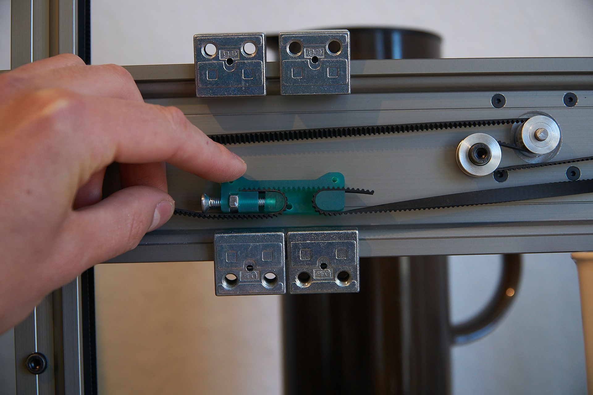


") the I150-PF type is the easiest to print and should be sufficient for your bearings.
the I150-PF type is the easiest to print and should be sufficient for your bearings.