Duet3D Logo Duet3D
    • Tags
    • Documentation
    • Order
    • Register
    • Login

    Input Shapers: 2HUMP_EI & 3HUMP_EI + Auto Tuning

    Scheduled Pinned Locked Moved
    Firmware wishlist
    20
    64
    10.9k
    Loading More Posts
    • Oldest to Newest
    • Newest to Oldest
    • Most Votes
    Reply
    • Reply as topic
    Log in to reply
    This topic has been deleted. Only users with topic management privileges can see it.
    • GeneRisiundefined
      GeneRisi @dc42
      last edited by

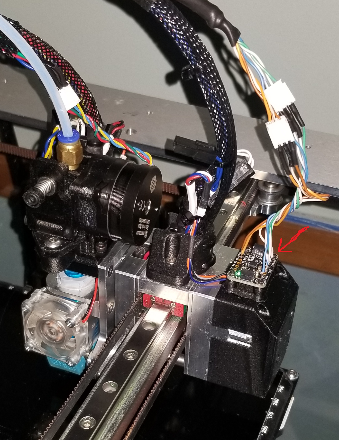
      @dc42 I have my accelerometer set up on my tool changer. I mounted it like this:
      Accel.png

      Are any of the input shapers in the version you put into the dropbox?

      Thanks!

      1 Reply Last reply Reply Quote 0
      • GeneRisiundefined
        GeneRisi @dc42
        last edited by

        @dc42 FWIW - I also am thinking that the table the printer is on vibrates. Could a second accelerometer could be used to measure the vibration of the printer frame and subtract it from the samples collected on the carriage? The accelerometer is measuring all vibrations, not just the vibrations of the carriage inside the printer frame. I know that samples would have to be synchronous, or perhaps asynchronous and the Fourier results of the frame vibration subtracted from the Fourier results of the carriage vibration?

        o_lampeundefined 1 Reply Last reply Reply Quote 0
        • Argoundefined
          Argo @CNCModeller
          last edited by

          @cncmodeller

          Input shapers to generally have a range they reduce vibrations so it's not only a specific frequency they dampen but + / - x% from the specified input shaping frequency. Depending on the shaper the range is smaller or bigger.
          Nevertheless it is possible to change the input shaping frequency during a print.

          The object "move.extruders[0].position" should display the total amount of filament used so far and with some conditional gcode in the daemon.g you should be able to achieve your goal.

          1 Reply Last reply Reply Quote 0
          • o_lampeundefined
            o_lampe @GeneRisi
            last edited by o_lampe

            @generisi said in Input Shapers: 2HUMP_EI & 3HUMP_EI + Auto Tuning:

            I know that samples would have to be synchronous, or perhaps asynchronous and the Fourier results of the frame vibration subtracted from the Fourier results of the carriage vibration?

            By using the same file for both tests, one could write a specific start- and end movement (a number of fast/short back and forth moves) which would allow to match the results. (*) The input shaper would have to search for these patterns...

            *) calling a macro M98 P"ShakeItBaby.g"

            1 Reply Last reply Reply Quote 0
            • o_lampeundefined
              o_lampe @CNCModeller
              last edited by

              @cncmodeller said in Input Shapers: 2HUMP_EI & 3HUMP_EI + Auto Tuning:

              could there be a way to change the parameter during a print based on the amount of filament extruded?

              Adding filament will change the frequencies, but it also depends where you put it. In case of a Cartesian, the layer height has an influence. In case of a Polar bed, even the distance from bed-center is important.
              Then each layer of plastic adds a different amount of flexibility (PLA vs ABS, vs PETG)
              It's impossible to digest all that in a theoretic shaper model.
              Better measure online and correct on the fly

              JoergS5undefined 1 Reply Last reply Reply Quote 0
              • JoergS5undefined
                JoergS5 @o_lampe
                last edited by JoergS5

                Instead of input shaping, for global vibrations one could also create vibrations in opposite direction like a noise cancellation system for earphones. Maybe Piezo based, using LIS3DH as source of information.

                1 Reply Last reply Reply Quote 0
                • CCS86undefined
                  CCS86 @dc42
                  last edited by

                  @dc42 said in Input Shapers: 2HUMP_EI & 3HUMP_EI + Auto Tuning:

                  Yes, but perhaps not on the Duet Maestro because it doesn't have floating point hardware.

                  😬

                  Boy, I really hope it doesn't pan out that way. I have been really looking forward to this feature on my Maestro. Accelerometer on the way.

                  1 Reply Last reply Reply Quote 0
                  • appjawsundefined
                    appjaws
                    last edited by

                    I have a PT100 daughter board and my accelerometer is attached to my hot end assembly.
                    Could somebody point me in the direction of where to find how to connect the 2 boards and what changes are needed to config.g
                    Thanks

                    appjaws - Core XYUV Duet Ethernet Duex5
                    firmware 3.5.0-rc.4 Web Interface 3.5.0-rc.4
                    Ormerod 1-converted to laser engraver, Duet wifi
                    OpenSCAD version 2024.03.18
                    Simplify3D 5.1.2

                    oliofundefined Adrian52undefined 2 Replies Last reply Reply Quote 0
                    • oliofundefined
                      oliof @appjaws
                      last edited by

                      @appjaws https://duet3d.dozuki.com/Wiki/Accelerometers and https://duet3d.dozuki.com/Wiki/Gcode#Section_M955_Configure_Accelerometer should get you going

                      <>RatRig V-Minion Fly Super5Pro RRF<> V-Core 3.1 IDEX k*****r <> RatRig V-Minion SKR 2 Marlin<>

                      1 Reply Last reply Reply Quote 0
                      • Adrian52undefined
                        Adrian52 @appjaws
                        last edited by

                        @appjaws for the connection via the daughterboard see:
                        https://forum.duet3d.com/topic/22904/duet-2-wifi-accelerometer-connection/1

                        1 Reply Last reply Reply Quote 0
                        • appjawsundefined
                          appjaws
                          last edited by

                          Thanks for the help.
                          I am totally confused....(not hard)

                          from the Wiki*****
                          Two further signals must be connected on the accelerometer breakout board: SPI CS, and INT1. The INT1 pin must be connected to a Duet pin with interrupt capability. This is what we suggest:

                          On Duet WiFi, Duet Ethernet and Duet Maestro all the SPI CS pins have interrupt capability, so you can use any two spare CS pins on the daughter board connector. For example, on a Duet WiFi or Duet Ethernet you could connect the accelerometer CS pin to SPI.CS3, and the INT1 pin to SPI.CS4. Then use this command to tell RRF about it:
                          M955 P0 C"spi.cs3+spi.cs4"


                          I can not see any markings on my daughter board for SPI.CS3 or CS4

                          from the Wiki*****
                          To use a direct connection, connect the accelerometer MOSI (also called SDI), MISO (also called SDO), SCLK and GND pins to the corresponding pins on the SPI daughter board connector. You can also pick up +3.3V on the daughter board connector to feed to the Vcc pin of the accelerometer.


                          On the accelerometer the markings are:
                          I2,A3,A2,A1,SDO,CS

                          Vin, GND,SCL, SDA INT

                          So would SDI actually be SDA?
                          Would SCLK actually be SCL?
                          Where are the corresponding SCLK, GND, Vcc SDI,SDO, SPI.CS3, SPI.CS4 on the daughter board?

                          I already have a PT100 connected to RTD1 on the daughter board

                          appjaws - Core XYUV Duet Ethernet Duex5
                          firmware 3.5.0-rc.4 Web Interface 3.5.0-rc.4
                          Ormerod 1-converted to laser engraver, Duet wifi
                          OpenSCAD version 2024.03.18
                          Simplify3D 5.1.2

                          sebkritikelundefined 1 Reply Last reply Reply Quote 0
                          • sebkritikelundefined
                            sebkritikel @appjaws
                            last edited by sebkritikel

                            @appjaws Here is my wiring diagram I used when connecting to the daughter board header on the Duet2 - see important notes below about actually connecting to the daughter board itself.
                            7b3e641b-21ba-421d-ab7d-027b2314b1f8-image.png

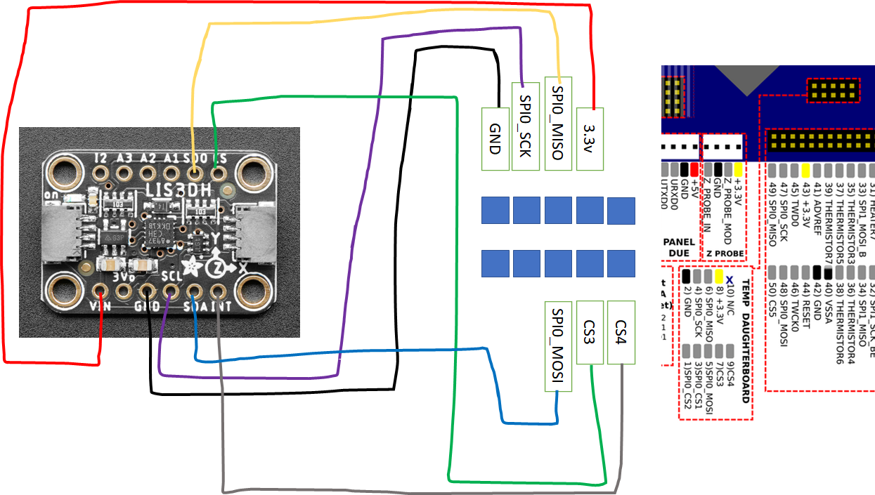
                            For the daughter board, I think the two key notes are

                            You would have needed to use spi.cs3 or spi.cs4(because spi.cs1 and spi.cs2 are used by the daughter board. Those pins are routed to the top of the daughter board on different pins (the pins that would be spi.cs1 and spi.cs2 respectively if those were routed straight through).

                            and

                            So when connecting via the daughterboard, I should connect cs to pin position 3, and int1 to pin position 1, to pick up cs3 and cs4?

                            Using M955 P0 C"spi.cs3+spi.cs4"

                            Large(ish?) IDEX - 6HC, 1HCL
                            Stratasys Dimension 1200es to 6HC Conversion

                            appjawsundefined 1 Reply Last reply Reply Quote 0
                            • appjawsundefined
                              appjaws @sebkritikel
                              last edited by

                              @sebkritikel perfect, thanks, I'll crack on in the morning.

                              appjaws - Core XYUV Duet Ethernet Duex5
                              firmware 3.5.0-rc.4 Web Interface 3.5.0-rc.4
                              Ormerod 1-converted to laser engraver, Duet wifi
                              OpenSCAD version 2024.03.18
                              Simplify3D 5.1.2

                              dc42undefined 1 Reply Last reply Reply Quote 0
                              • dc42undefined
                                dc42 administrators @appjaws
                                last edited by

                                @appjaws, the diagram posted by @sebkritikel is valid if you don't have a daughter board already plugged into the connector.

                                If you do have a single daughter board plugged in to it, then on the top of the daughterboard CS3 and CS4 are shifted 3 pins to the left in the above diagram. CS1 and CS2 are not available because the daughter board uses them.

                                Duet WiFi hardware designer and firmware engineer
                                Please do not ask me for Duet support via PM or email, use the forum
                                http://www.escher3d.com, https://miscsolutions.wordpress.com

                                CCS86undefined 1 Reply Last reply Reply Quote 2
                                • CCS86undefined
                                  CCS86 @dc42
                                  last edited by

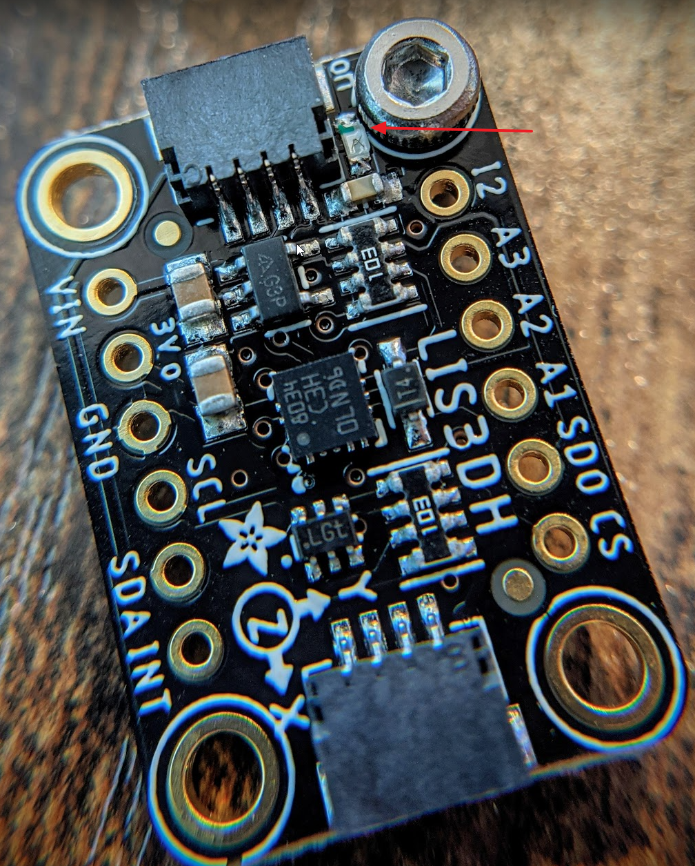
                                  Accelerometer has arrived.

                                  Man, this component is close to the mounting screw! Might have to grind down the head.

                                  f148701e-fba2-48d3-935b-0fa3c4a0f350-image.png

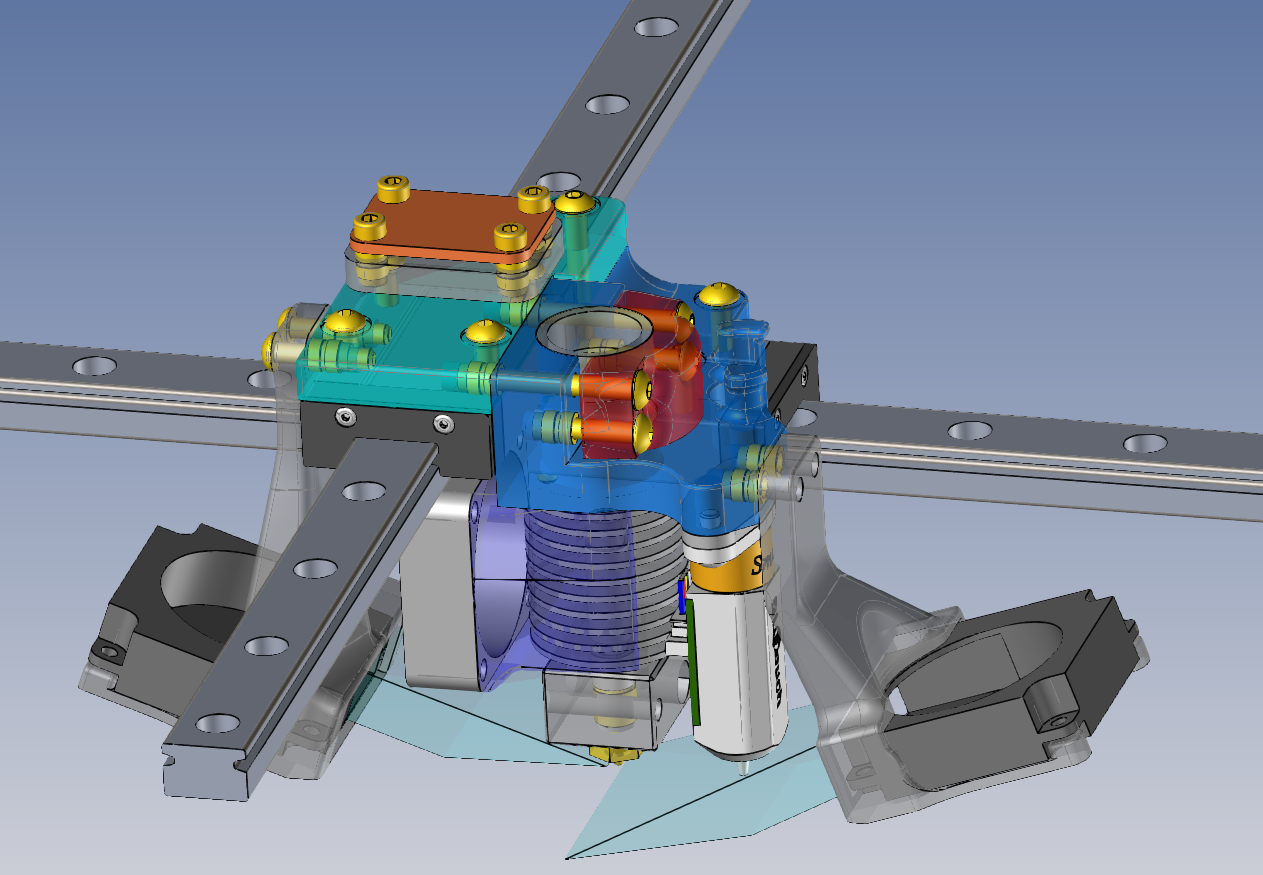
                                  Have a nice mount for my carriage designed and ready to print:

                                  e131a631-7f70-488d-be4e-925920d86589-image.png

                                  @dc42 What are the odds input shaping makes it to the Maestro?

                                  dc42undefined 1 Reply Last reply Reply Quote 0
                                  • dc42undefined
                                    dc42 administrators @CCS86
                                    last edited by

                                    @ccs86 said in Input Shapers: 2HUMP_EI & 3HUMP_EI + Auto Tuning:

                                    What are the odds input shaping makes it to the Maestro?

                                    Not good, because the Maestro does not have hardware floating point.

                                    Duet WiFi hardware designer and firmware engineer
                                    Please do not ask me for Duet support via PM or email, use the forum
                                    http://www.escher3d.com, https://miscsolutions.wordpress.com

                                    CCS86undefined 1 Reply Last reply Reply Quote 0
                                    • CCS86undefined
                                      CCS86 @dc42
                                      last edited by

                                      @dc42 said in Input Shapers: 2HUMP_EI & 3HUMP_EI + Auto Tuning:

                                      @ccs86 said in Input Shapers: 2HUMP_EI & 3HUMP_EI + Auto Tuning:

                                      What are the odds input shaping makes it to the Maestro?

                                      Not good, because the Maestro does not have hardware floating point.

                                      That is super disappointing to hear. I was under the impression that it did: https://duet3d.dozuki.com/Wiki/Comparison_of_Duets_vs._other_32-bit_controller_boards

                                      zaptaundefined 1 Reply Last reply Reply Quote 0
                                      • zaptaundefined
                                        zapta @CCS86
                                        last edited by

                                        @ccs86, notice the difference in the link you posted between Maestro and Duet2, one is M4 and one is M4F.

                                        https://en.wikipedia.org/wiki/ARM_Cortex-M#Cortex-M4 .

                                        Sometimes the fine prints make a big difference. 😉

                                        CCS86undefined 1 Reply Last reply Reply Quote 1
                                        • CCS86undefined
                                          CCS86 @zapta
                                          last edited by

                                          @zapta said in Input Shapers: 2HUMP_EI & 3HUMP_EI + Auto Tuning:

                                          @ccs86, notice the difference in the link you posted between Maestro and Duet2, one is M4 and one is M4F.

                                          https://en.wikipedia.org/wiki/ARM_Cortex-M#Cortex-M4 .

                                          Sometimes the fine prints make a big difference. 😉

                                          I was talking about this:

                                          50885797-25c6-466e-bf79-2a1ff661f18e-image.png

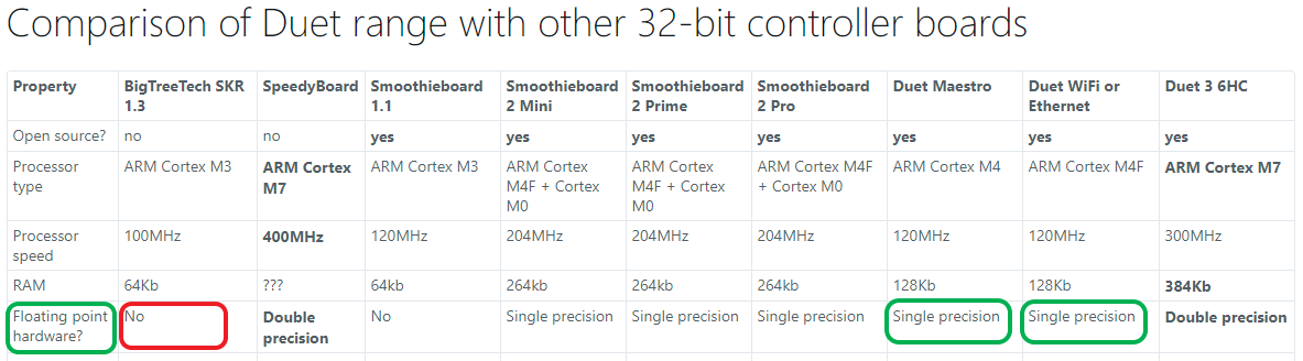
                                          This reads to me as the Maestro having floating point hardware. So, when one of the most anticipated firmware features isn't likely to be supported on the Maestro because of a "lack of floating point hardware", it seems reasonable to be confused/disappointed.

                                          zaptaundefined dc42undefined 2 Replies Last reply Reply Quote 0
                                          • zaptaundefined
                                            zapta @CCS86
                                            last edited by zapta

                                            @ccs86 said in Input Shapers: 2HUMP_EI & 3HUMP_EI + Auto Tuning:

                                            it seems reasonable to be confused/disappointed.

                                            Good point. It is represented to have hardware FP similar to the Duet2 which is expected to support input shaping. Same goes for RAM size and CPU speed.

                                            1 Reply Last reply Reply Quote 0
                                            • First post
                                              Last post
                                            Unless otherwise noted, all forum content is licensed under CC-BY-SA