Duet3D Logo Duet3D
    • Tags
    • Documentation
    • Order
    • Register
    • Login

    Duet Wifi Closed Loop and Panel Due

    Scheduled Pinned Locked Moved
    Accessories and Add-ons
    breakout board closed loop help panel due setup wiring
    5
    23
    1.8k
    Loading More Posts
    • Oldest to Newest
    • Newest to Oldest
    • Most Votes
    Reply
    • Reply as topic
    Log in to reply
    This topic has been deleted. Only users with topic management privileges can see it.
    • Gost101undefined
      Gost101 @alankilian
      last edited by

      @alankilian @JoergS5 Does this mean you guys can help me? I have no idea as per which connector on the breadboard connects to which connector on the closed loop board.

      1 Reply Last reply Reply Quote 0
      • Phaedruxundefined
        Phaedrux Moderator
        last edited by

        https://github.com/bigtreetech/BIGTREETECH-Stepper-Motor-Driver/blob/master/S42B/V2.0/42 Stepper Motor Closed Loop Driver Control Board Manual.pdf

        Did you take a look at the manual from that github link?

        Have you tried connecting the step/direction/enable from the breakout board to the closed loop board yet?

        Z-Bot CoreXY Build | Thingiverse Profile

        Gost101undefined 1 Reply Last reply Reply Quote 0
        • Gost101undefined
          Gost101 @Phaedrux
          last edited by

          @phaedrux I have, no luck.

          alankilianundefined 1 Reply Last reply Reply Quote 0
          • alankilianundefined
            alankilian @Gost101
            last edited by

            @gost101 HERE'S a thread showing how to connect a different stepper driver to the expansion connector.

            It looks like you connect step/direction/enable to the minus pins on the expansion.
            Also, 3.3 Volts and ground.
            Also power for the stepper motor (12V?) and ground.

            SeemeCNC Rostock Max V3 converted to V3.2 with a Duet2 Ethernet Firmware 3.2 and SE300

            Gost101undefined 1 Reply Last reply Reply Quote 1
            • Gost101undefined
              Gost101 @alankilian
              last edited by

              @alankilian Which Pin connector should the GND, 5V/3.3V, & Power 12V/24V connect to on the Expansion board?

              JoergS5undefined alankilianundefined 3 Replies Last reply Reply Quote 0
              • JoergS5undefined
                JoergS5 @Gost101
                last edited by JoergS5

                This post is deleted!
                1 Reply Last reply Reply Quote 0
                • JoergS5undefined
                  JoergS5 @Gost101
                  last edited by

                  This post is deleted!
                  1 Reply Last reply Reply Quote 0
                  • alankilianundefined
                    alankilian @Gost101
                    last edited by

                    @gost101 Connect GND and +5 Volts from one of the two Heater connectors.

                    You'll need to get 12 or 24 Volts from the Duet mainboard.

                    SeemeCNC Rostock Max V3 converted to V3.2 with a Duet2 Ethernet Firmware 3.2 and SE300

                    1 Reply Last reply Reply Quote 0
                    • Gost101undefined
                      Gost101
                      last edited by

                      @alankilian Is there a 12v connector on the board I can use?

                      engikeneerundefined 1 Reply Last reply Reply Quote 0
                      • engikeneerundefined
                        engikeneer @Gost101
                        last edited by

                        @gost101 assuming you're using a 12V PSU, just take it straight from that. The Duet WiFi doesn't have an internal 12V regulator, so if you have a 24V PSU, you can only supply 24v

                        E3D TC with D3Mini and Toolboards.
                        Home-built CoreXY, Duet Wifi, Chimera direct drive, 2x BMG, 300x300x300 build volume
                        i3 clone with a bunch of mods

                        1 Reply Last reply Reply Quote 0
                        • Gost101undefined
                          Gost101
                          last edited by

                          @alankilian Thats what I thought but wasn't entirely sure. I'll let you know if it works, when I get back home.

                          1 Reply Last reply Reply Quote 0
                          • Gost101undefined
                            Gost101
                            last edited by

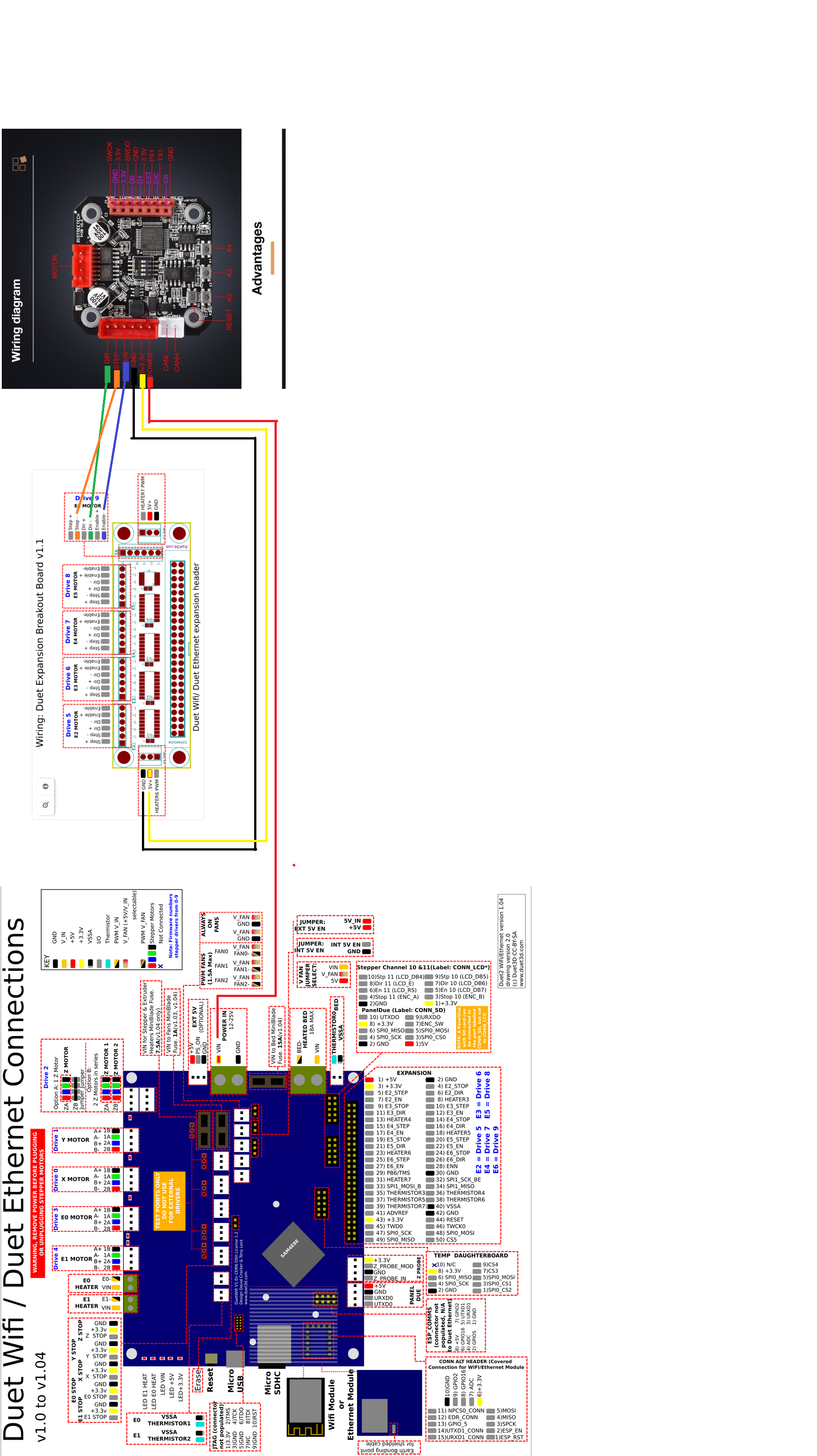
                            I made a quick wiring diagram in paint.

                            Wiring Diagram.png

                            1 Reply Last reply Reply Quote 0
                            • Gost101undefined
                              Gost101
                              last edited by

                              @alankilian @I have 5 closed loop stepper drivers for context. Can I connect all of the closed loops stepper drivers to the same 5V and Ground Terminal or would that break something?

                              alankilianundefined 1 Reply Last reply Reply Quote 0
                              • alankilianundefined
                                alankilian @Gost101
                                last edited by

                                @gost101 That will be fine as long as you don't draw too much current for the 5 Volt supply or the connector you are using.

                                SeemeCNC Rostock Max V3 converted to V3.2 with a Duet2 Ethernet Firmware 3.2 and SE300

                                1 Reply Last reply Reply Quote 1
                                • First post
                                  Last post
                                Unless otherwise noted, all forum content is licensed under CC-BY-SA