Mushrooming print - What could cause this?
-
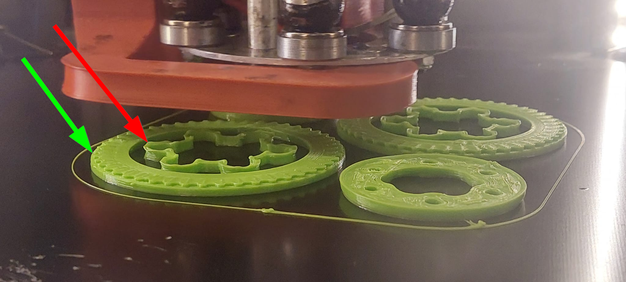
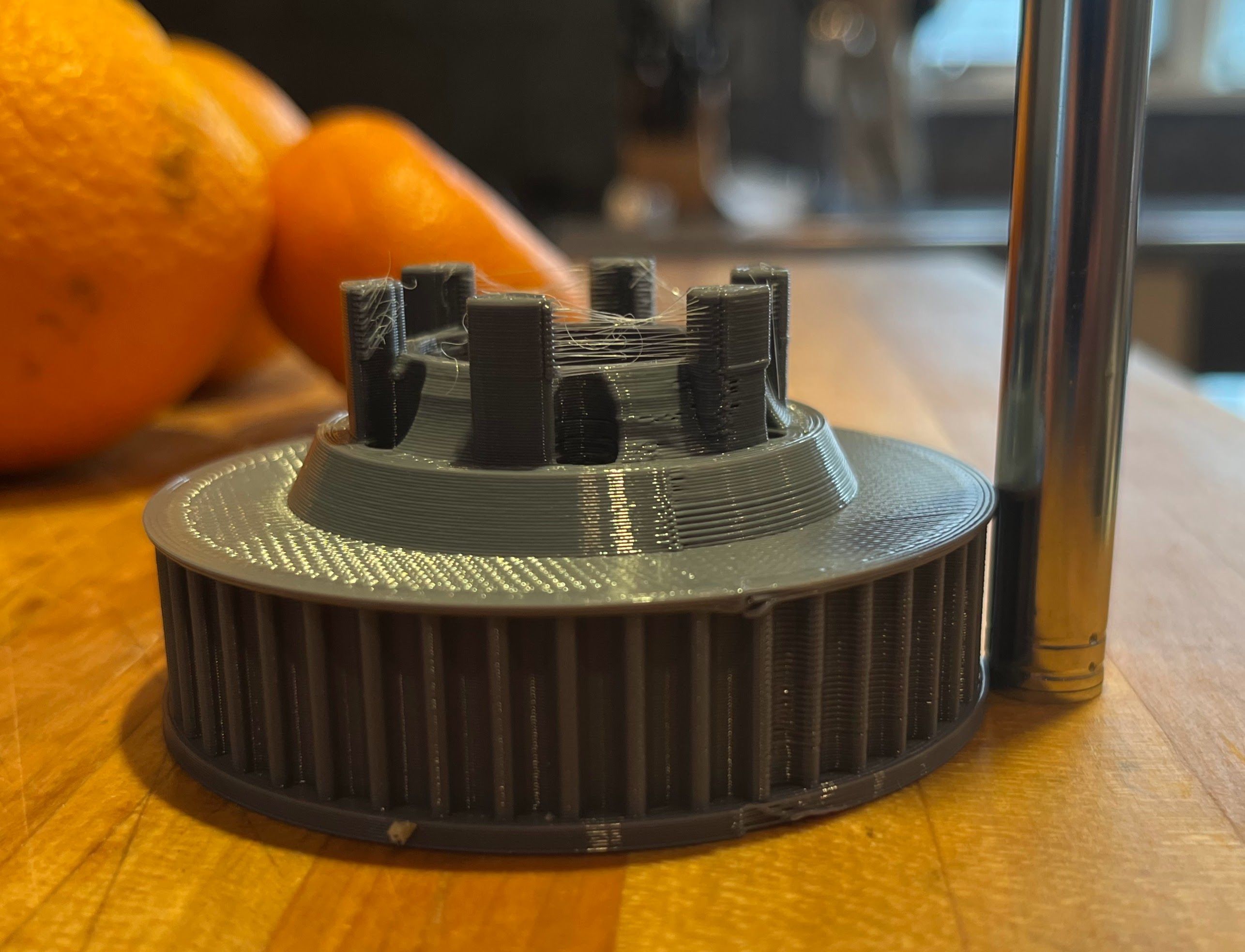
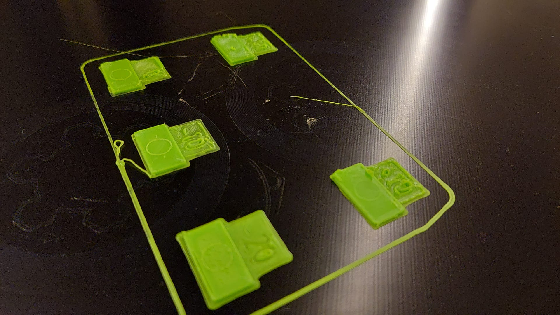
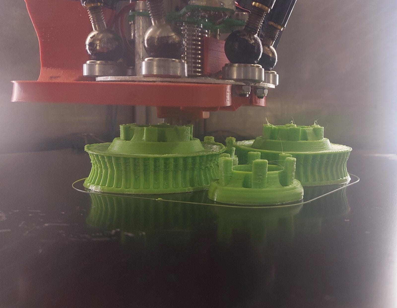
As I have started printing larger object, I have noticed a printing defect I have not seen anyone discuss before: The print walls seem to deflect first inwards in the first layers and then outwards in later layers.
See the images below:
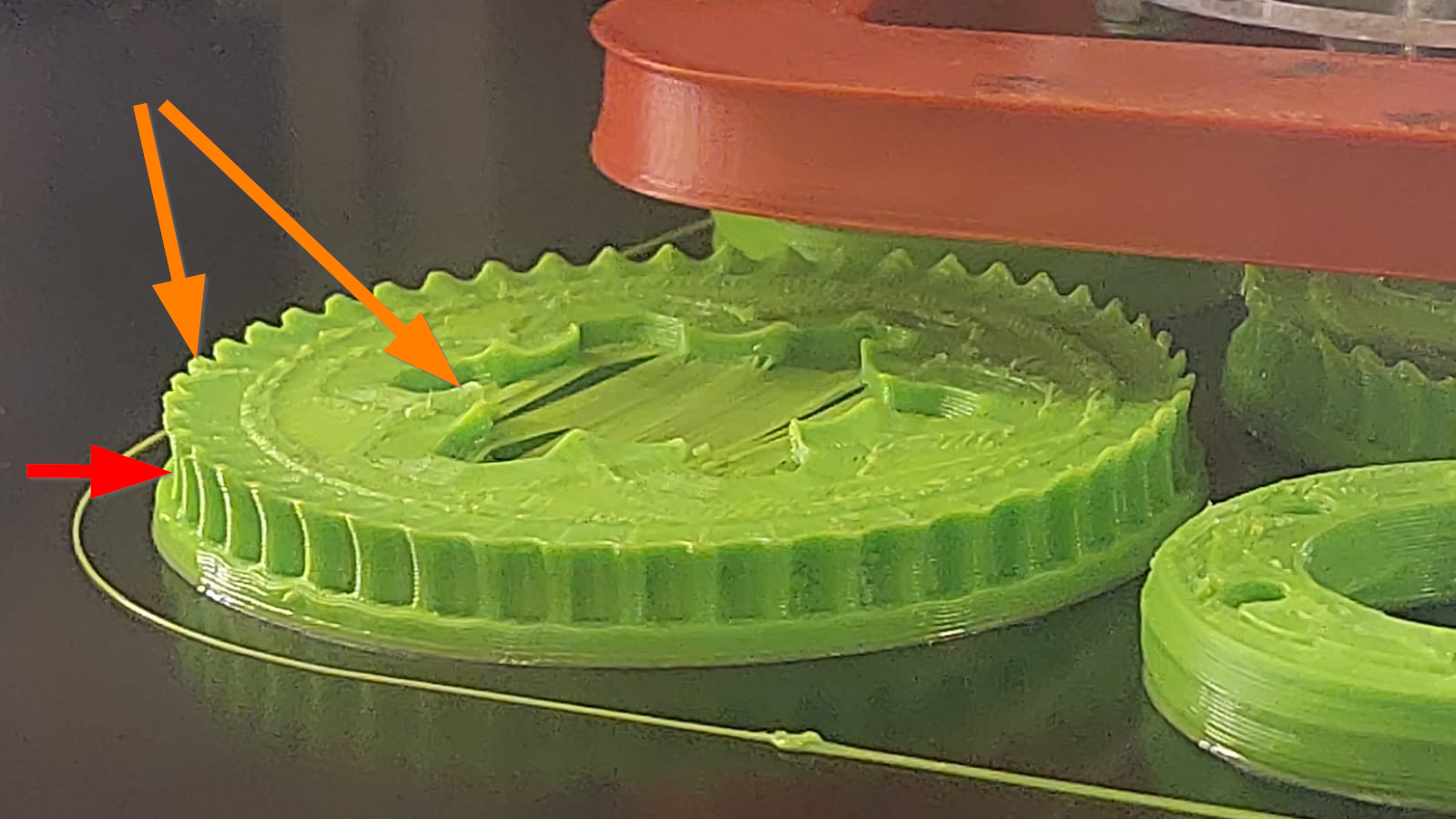
The teeth on the pulleys are supposed to be vertical.
The effect is more pronounced in the center of the bed, between the pulleys.
Please also note the low quality of the print in the teeth area, while the smaller washers have much better perimeter quality.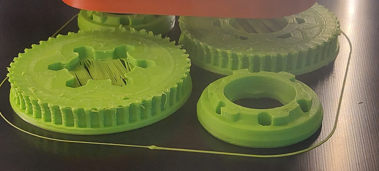
Details:
- ASA filament @ 250°c (Same effect with ABS, not yet printed in PLA on this printer)
- FR4/G10 Heated bed: first layer @100°c, then 85°c for the rest of the print
- Delta printer with nozzle probing (strain gauge on the effector holding the hot end)
- 6-factor calibration is performed 3 times every time I remove the bed
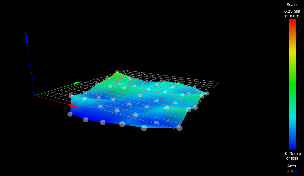
- Mesh leveling performed before every print
- The above images are from a 10-perimeter, 100% infill print, but the same effect is seen in 2-perimeter, 10% infill prints.
Do you have any thoughts on what could cause this?
some more images below:
Config.g
; Configuration file for Duet WiFi (firmware version 3) ; executed by the firmware on start-up ; ; generated by RepRapFirmware Configuration Tool v3.1.4 on Sun Jul 19 2020 22:30:32 ; General preferences G90 ; send absolute coordinates... M83 ; ...but relative extruder moves M550 P"Goliath" ; set printer name M665 R172.66 L511.07 B140 H330.5 ; Set delta radius, diagonal rod length, printable radius and homed height (should be R150, but fan is too large!) M666 X0 Y0 Z0 ; put your endstop adjustments here, or let auto calibration find them ; Network M552 S1 ; enable network M586 P0 S1 ; enable HTTP M586 P1 S0 ; disable FTP M586 P2 S0 ; disable Telnet ; Drives M569 P0 S0 ; physical drive 0 goes backwards M569 P1 S1 ; physical drive 1 goes forwards M569 P2 S0 ; physical drive 2 goes backwards M569 P3 S1 ; physical drive 3 goes forwards M584 X0 Y1 Z2 E3 ; set drive mapping M350 X16 Y16 Z16 E16 I1 ; configure microstepping with interpolation M92 X100.00 Y100.00 Z100.00 E137.82 ; set steps per mm (E is 430 for bondtech, 137.82 for creality) M566 X600.00 Y600.00 Z600.00 E1200.00 ; set maximum instantaneous speed changes (mm/min) (was [x,y,z]=1200) M203 X9000.00 Y9000.00 Z9000.00 E6000.00 ; set maximum speeds (mm/min) (was [x,y,z]=18000) Extruder changer to 6000 from 1200 M201 X500.00 Y500.00 Z500.00 E1000.00 ; set accelerations (mm/s^2) (was [x,y,z]=1000) M906 X1000 Y1000 Z1000 E1500 I30 ; set motor currents (mA) and motor idle factor in per cent M84 S30 ; Set idle timeout ; Axis Limits M208 Z0 S1 ; set minimum Z ; Endstops M574 X2 S1 P"!xstop" ; configure active-high endstop for high end on X via pin !xstop M574 Y2 S1 P"!ystop" ; configure active-high endstop for high end on Y via pin !ystop M574 Z2 S1 P"!zstop" ; configure active-high endstop for high end on Z via pin !zstop ; Z-Probe ; Original command before 2021-10-23 was "M558 P5 C"!zprobe.in" H3 F500 T6000 ;A3 S0.01" ; ! because Z-strain-probe is inverted (Documentation says NC switches are best practice, I took the advice even though this isn't a switch per se). ; Reduced F500 to F50 for testing ; Changed G31 from "G31 P500 X30.31 Y17.5 Z2.2" to "G31 P500 X0.0 Y0.0 Z0.0" ; P5 (filtered digital) or P8 (unfiltered digital) ; ^ enables pull up resistor on input M558 P8 C"!zprobe.in" H5 F250 T6000 R1.5 ;A5 S0.01 ; set Z probe type to switch and the dive height + speeds (was 120mm/sec) G31 P500 X0.0 Y0.0 Z-0.35 ; set Z probe trigger value, offset and trigger height [Nozzle lifts when triggered, and pushes bed down slightly. was 0.3mm, updated to 0.35 after the probing was chnaged to "probe when extruder is cold"] M557 R140 S35 ;Set probing radius to 140mm with a probe spacing of 35mm ; Heaters M308 S0 P"bedtemp" Y"thermistor" A"Bed" T100000 B4725 C7.060000e-8 ; configure sensor 0 as thermistor on pin bedtemp M950 H0 C"bedheat" T0 ; create bed heater output on bedheat and map it to sensor 0 M307 H0 B1 S1.00 ; enable bang-bang mode for the bed heater and set PWM limit M140 H0 ; map heated bed to heater 0 M143 H0 S135 ; set temperature limit for heater 0 to 135C M308 S1 P"e0temp" Y"thermistor" A"Extruder" T100000 B4725 C7.060000e-8 ; configure sensor 1 as thermistor on pin e0temp M950 H1 C"e0heat" T1 ; create nozzle heater output on e0heat and map it to sensor 1 M307 H1 B0 S1.00 ; disable bang-bang mode for heater and set PWM limit M143 H1 S300 ; set temperature limit for heater 1 to 300C M308 S2 P"e1temp" Y"thermistor" A"Chamber" T100000 B4725 C7.060000e-8 ; configure sensor 2 as thermistor on pin e1temp (chamber thermistor) ; Fans M950 F0 C"fan0" Q100 ; create fan 0 on pin fan0 and set its frequency M106 P0 X1 H1 T45 ; set fan Thermostatic control is turned on based on heater1 (H1) temperature probe M950 F1 C"fan1" Q100 ; Tools M563 P0 S"Extruder0" D0 H1 F1 ; define tool 0: uses Drive0, Heater1 and Fan1 (Fan0 is mapped to thermostatic control) G10 P0 X0 Y0 Z0 ; set tool 0 axis offsets G10 P0 R0 S0 ; set initial tool 0 active and standby temperatures to 0C ; Lighting M950 P0 C"e1heat" ; create output port 0 attached to heater 1\ M42 P0 S0.1 ; Turn on Case light 10% ;Tool Selection T0 ; Load Custom settings M501 ;Setup power failure procedure M911 S21.0 R23.0 P"G91 M83 G1 Z3 E-5 F1000" ;Set relative movement mode (G91) ;Set relative extrusion mode (M83) ;Simultaneously lift the head and retract filament (G1 Z3 E-5 F1000) Bed.g (in case it matters):
; bed.g file for RepRapFirmware, generated by Escher3D calculator ; 16 points, 6 factors, probing radius: 140, probe offset (0, 0) ; This is for the Delta calibration, not for the mesh bed leveling - don't delete this! ; https://www.escher3d.com/pages/wizards/wizardbed.php G28 G30 P0 X0.00 Y140.00 Z-99999 H0 G30 P1 X89.99 Y107.25 Z-99999 H0 G30 P2 X137.87 Y24.31 Z-99999 H0 G30 P3 X121.24 Y-70.00 Z-99999 H0 G30 P4 X47.88 Y-131.56 Z-99999 H0 G30 P5 X-47.88 Y-131.56 Z-99999 H0 G30 P6 X-121.24 Y-70.00 Z-99999 H0 G30 P7 X-137.87 Y24.31 Z-99999 H0 G30 P8 X-89.99 Y107.25 Z-99999 H0 G30 P9 X0.00 Y70.00 Z-99999 H0 G30 P10 X60.62 Y35.00 Z-99999 H0 G30 P11 X60.62 Y-35.00 Z-99999 H0 G30 P12 X0.00 Y-70.00 Z-99999 H0 G30 P13 X-60.62 Y-35.00 Z-99999 H0 G30 P14 X-60.62 Y35.00 Z-99999 H0 G30 P15 X0 Y0 Z-99999 S6 -
General over extrusion?
Or perhaps the z axis isn't moving the expected amount?
Or perhaps your bed is expanding over the course of the print?
-
@leav
Are you shure that your delta is built correctly?
bed in right angle to the towers, rod length, radius, ...I think, some wrong parameters/dimensions can cause this "mushrooming".
EDIT: can it be that the effector is tilting?
-
@phaedrux said in Mushrooming print - What could cause this?:
General over extrusion?
Or perhaps the z axis isn't moving the expected amount?
Or perhaps your bed is expanding over the course of the print?
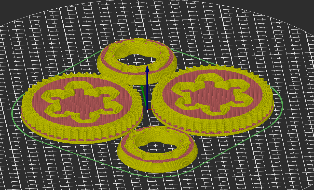
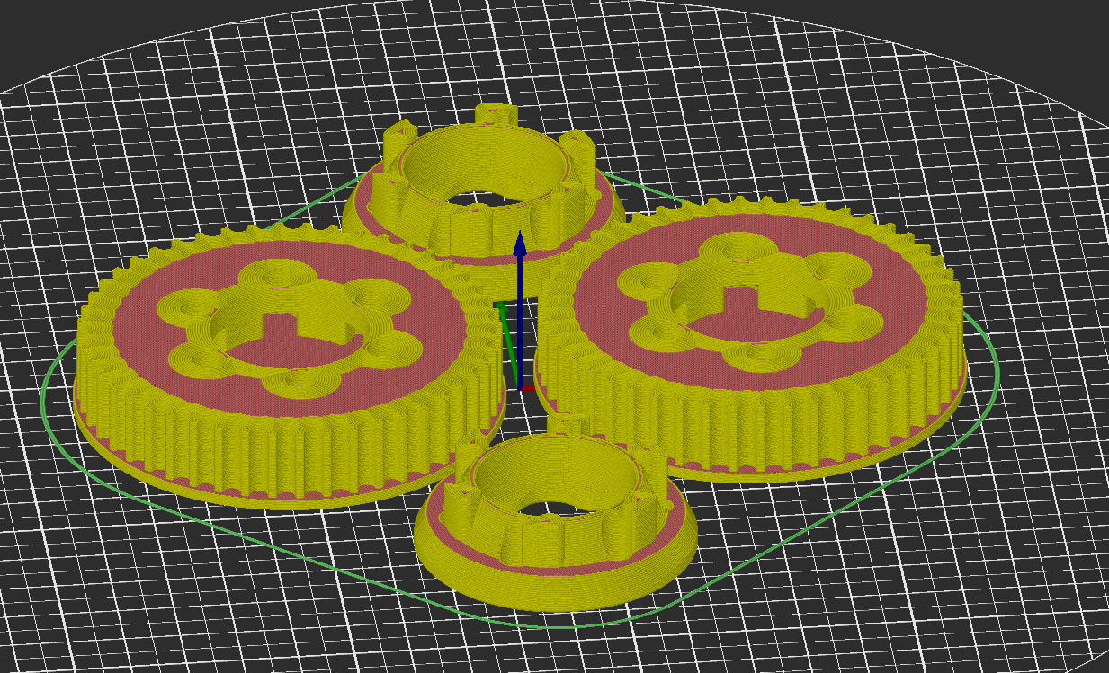
I was going to say "no way" to over extrusion, but I ran some more tests and noticed the effect is more noticeable when there is "gap filling" involved.
The images below show slicer vs. reality (new slicing, not the same parameters as the original post):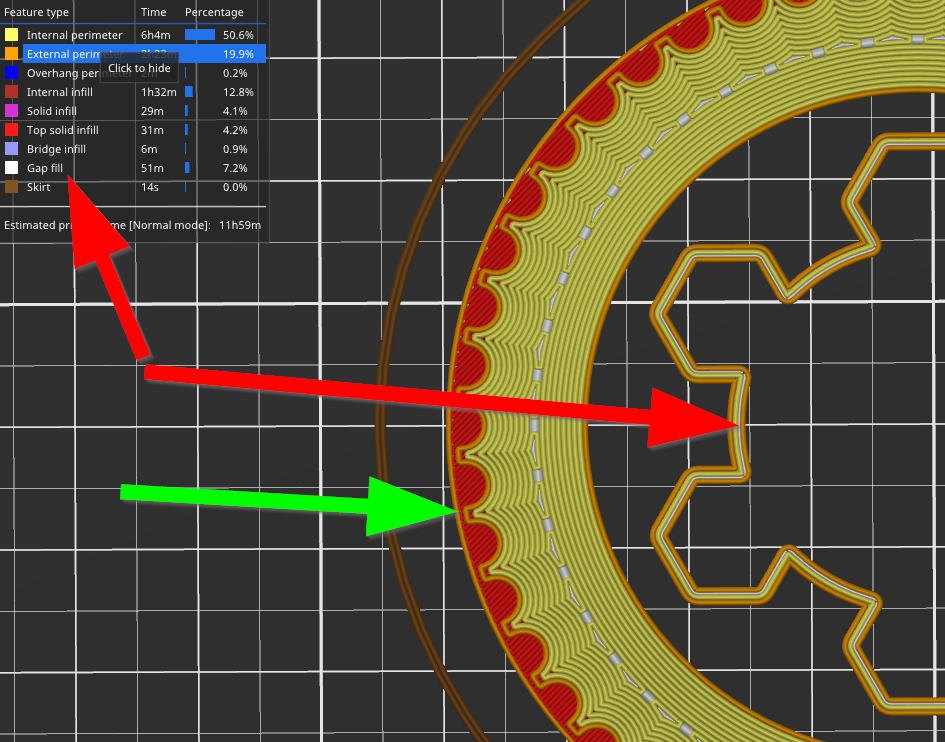

The effect did repeat itself in the teeth later in the print (red) along with some curling/overextrusion effect:
100% infill is challenging, especially if your extrusion isn't properly calibrated.. I'll calibrate and post back for posterity.
@cosmowave said in Mushrooming print - What could cause this?:
@leav
Are you sure that your delta is built correctly?
bed in right angle to the towers, rod length, radius, ...I think, some wrong parameters/dimensions can cause this "mushrooming".
EDIT: can it be that the effector is tilting?
Thanks for the thoughts. The geometry is defined by a laser cut plate, so should be pretty good - I double checked and don't see any major errors. wouldn't hurt to measure the rod length again to double check - I'll do that.
One thing about my printer: I know for a fact that the plane of the printing bed is not perpendicular to the vertical rails. I wonder if the delta calibration algorithm assumes it is, or if it can compensate for that as well....
-
@leav
I took a closer look to your pictures and the magnet/ball rods look suspicious to me. Are you sure the rods stay centered on the magnets?
Haydn Huntley's mag-rods come with a Delrin sleeve for a reason... -
@o_lampe the balls are attached to the rods and the magnets have a corresponding cup for the balls. Still not the best design...
-
To me it looks like it could be a serious case of the material being way too hot.
the lifting of the print in the corners does scream that the part isnt cooling down before the next layer is added.May I ask, what Speeds, layerheights and infill%. Also part cooling (including what type of fan and quantity).
That being said, the bed mesh does also look suspect, there is a lot of variance in something that should be relatively smooth.
-
@jay_s_uk said in Mushrooming print - What could cause this?:
@o_lampe the balls are attached to the rods and the magnets have a corresponding cup for the balls. Still not the best design...
The magnets are much smaller than those from Haydn. Maybe the rods loose contact at the (sharper) turningpoint of a move?
The circular parts look relatively good, but the teeth.... -
I hear all your thoughts regarding the magnetic cups, I'll give you my own experience with them:
- They feel retained very well with zero backlash under low loads
- If the nozzle collides with the print in any meaningful way, they disconnect totally and very obviously
- In rare cases I've seen them disconnect and reconnect, but this has always been a prelude to a permanent disconnect as described above
- Of course it is possible that what we're seeing are micro disconnects of some sort, but I have a hard time believing the joints would hold on so reliably under disconnect conditions
I decided I don't understand the issue enough so printed some stuff and I have some more data to chew on...
First I calibrated the extrusion using SuperSlicer's generated test:
I settled on 0.92 extrusion multiplier because the -20% circle looked under extruded, and set out to print the whole set to gather more data:
Honestly, I'm at a loss. I can't imagine any sort of issue that could cause this.
The effect is roughly uniform in Z, and has a radial symmetry in the pulleys, so based on my understanding of Deltas, I feel like this should rule out any geometric issues within the system.
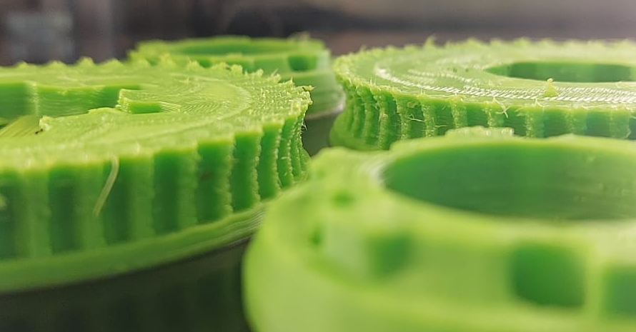
There is a transition in the section in the pulley in this area, see the lower part:
And the upper part:
I'll have to sleep on this. Happy to get any thoughts you have and test any theories put forth.
As this looks like it could be contraction, I guess maybe the next step is to test PLA? (never printed PLA before)
-
Is there any way you could post your STL files (And GCODE for comparison?)
I'd love to try printing this on my Delta to see if there's anything in the model or sliced code that's causing this.
-
@leav could it simply be shrinkage/warping?
It looks like the faster layers without solid infil (I.e. the ones that are laid down faster) are just contracting, but the slower layers are maintaining size better.
I'd try a different reel/brand of filament, or a different material
-
@leav
At first glance it looks like over-extrusion or wrong Z-axis stepps.
The retract doesn't seem to be there either, if you look at the blobs on the skirt and where you move from the skirt to the first layer of the component, the filament runs through without interruption.
But this taper in the middle of the gears is very strange and can actually only be explained by a hardware problem.I would first measure all parts and make sure that all components and screws etc. are tight.
Then measure the axes (travel / stepps) precisely and also measure the extruder stepps again to see whether 100mm is really being conveyed there if this was set in the DWC.Then I would check the bed level sensor to see if it is delivering accurate readings.
I can not imagine that the glass bed is so crooked.
You should also do a PID tuning of the hotend and the print bed.Once that is done, the flow must be determined and set correctly in the slicer.
Do it meticulously, i.e. measure the filament diameter etc.Do some test prints to find out the best temperature for your filament.
At least that's how I would do it in your case.
Google Translate
----- Original Text -----Auf den ersten Blick sieht es nach Überextrusion oder falschen Stepps der Z-Achse aus.
Auch der Retract scheint gar nicht vorhanden zu sein, wenn man sich die Kleckse beim Skirt so ansieht und wo vom Skirt zum ersten Layer des Bauteils gefahren wird, da läuft das Filament durch ohne Unterbrechung.
Aber diese Verjüngung in der Mitte der Zahnräder ist schon sehr merkwürdig und eigentlich nur durch ein Hardware-Problem zu erklären.Ich würde erst einmal alle Teile vermessen und auf den festen Sitz aller Bauteile und Schrauben etc. achten.
Dann die Achsen (Verfahrwege / Stepps) genauestens vermessen und auch die Extruder Stepps nochmals vermessen ob dort wirklich 100mm gefördert wird wenn dieses im DWC eingestellt wurde.Dann würde ich den Bed-Level-Sensor überprüfen ob er genaue Werte liefert.
Ich kann mir nicht vorstellen dass das Glasbett so schief und krumm ist.
Auch ein PID-Tuning vom Hotend und vom Druckbett solltest Du machen.Ist das erledigt, dann muss der Fluss ermittelt werden und im Slicer richtig eingestellt werden.
Mache es ganz penibel, also mit messen des Filament Durchmessers etc.Mache einige Testdrucke um die beste Temperatur für Dein Filament heraus zu finden.
So zumindest würde ich in Deinem Fall vorgehen.
-
How about the rod-distance? The effector looks like the magnets are arranged in a regular pattern (more or less)
It seems easy to match the wrong pair of magnets, which would lead to non-parallel rods. -
@leav said in Mushrooming print - What could cause this?:
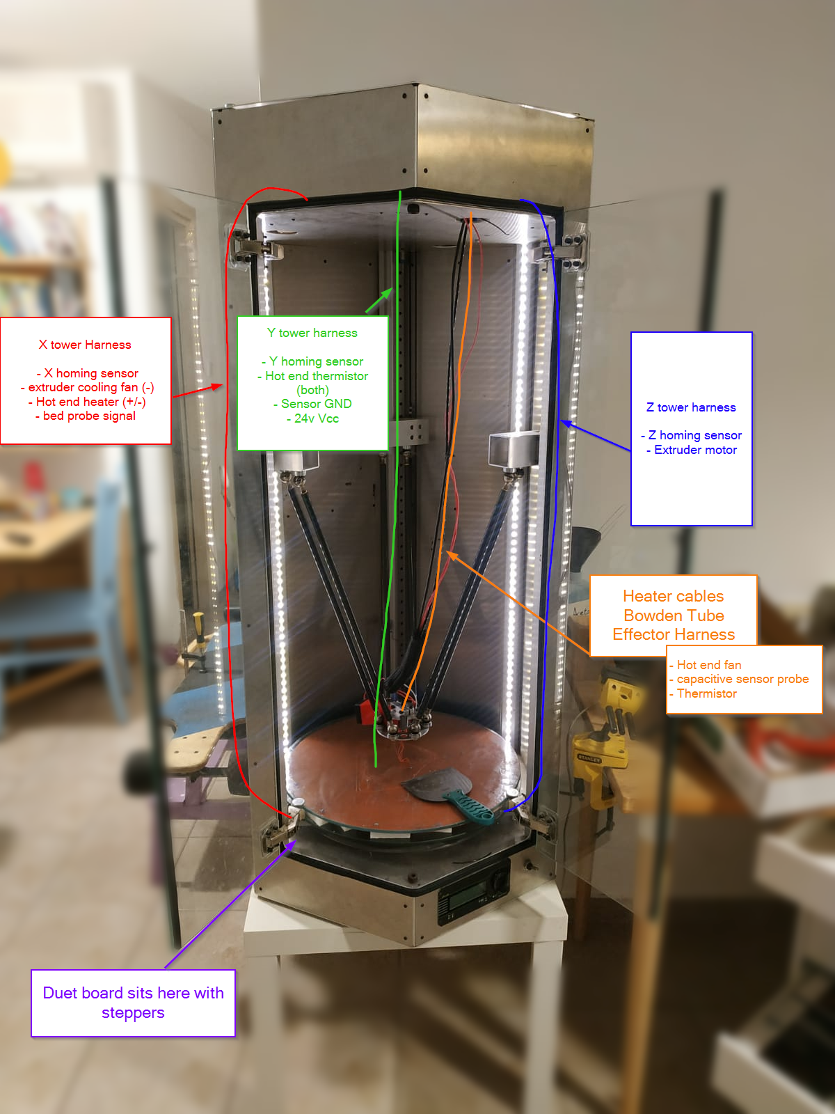
Did you use the printer to print the red fan-duct that you can see in the photo here ?
This effect can also be seen there, that the outer wall collapses inwards.
But it seems to be worse on the left side than on the right !?Print a 100mm high cylinder (or even higher) in vase mode and show us the result.
It is best to do this in different places on the print bed one after the other.
For example, as close as possible to each of the three Z-axes and once in the middle.Just to make it clear where this effect occurs.
Google Translate
----- Original Text -----Hast Du den roten Fan-Duct der hier auf dem Foto zu sehen ist, auch mit dem Drucker gedruckt ?
Dort ist dieser Effekt auch zu sehen, das die Außenwand nach innen einfällt.
Bei der linken Seite scheint es aber schlimmer zu sein als rechts !?Drucke doch mal einen etwa 100mm hohen Zylinder (oder auch gerne höher) im Vasenmodus und zeig uns das Ergebnis.
Am besten nacheinander an verschiedenen Stellen auf dem Druckbett.
Zum Beispiel so nah wie möglich an jedem der drei Z-Achsen und einmal in der Mitte.Nur um es einem bildlich klar zu machen wo überall dieser Effekt auftritt.
-
@alankilian said in Mushrooming print - What could cause this?:
Is there any way you could post your STL files (And GCODE for comparison?)
I'd love to try printing this on my Delta to see if there's anything in the model or sliced code that's causing this.
Shoot, I meant to do this with the previous post.
Here is a link to a zip with the two STL files and the SuperSlicer 3mf project (not sure if it's compatible with prusa slicer or other versions). Please let me know what you find.@engikeneer said in Mushrooming print - What could cause this?:
@leav could it simply be shrinkage/warping?
It looks like the faster layers without solid infil (I.e. the ones that are laid down faster) are just contracting, but the slower layers are maintaining size better.
I'd try a different reel/brand of filament, or a different material
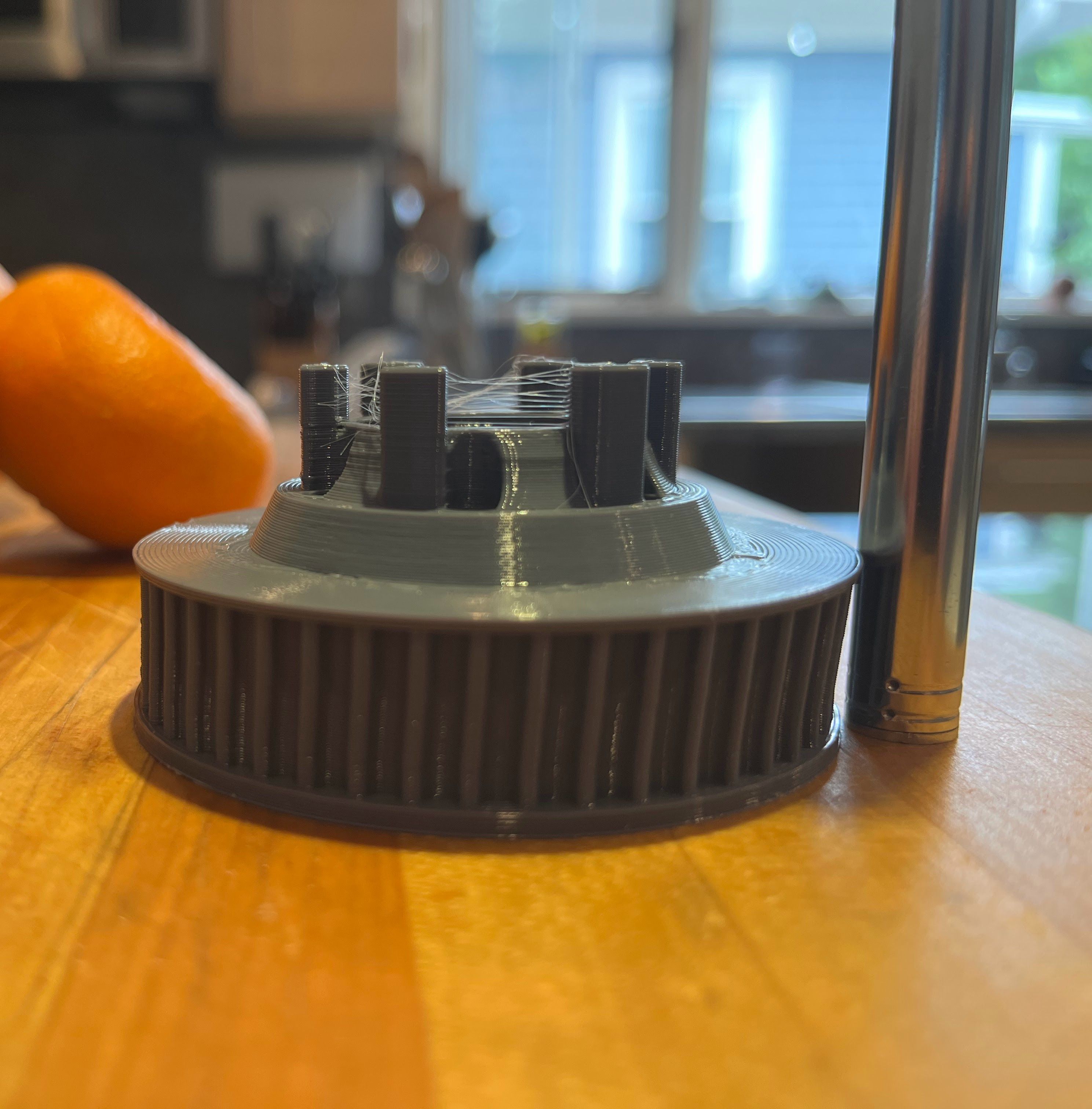
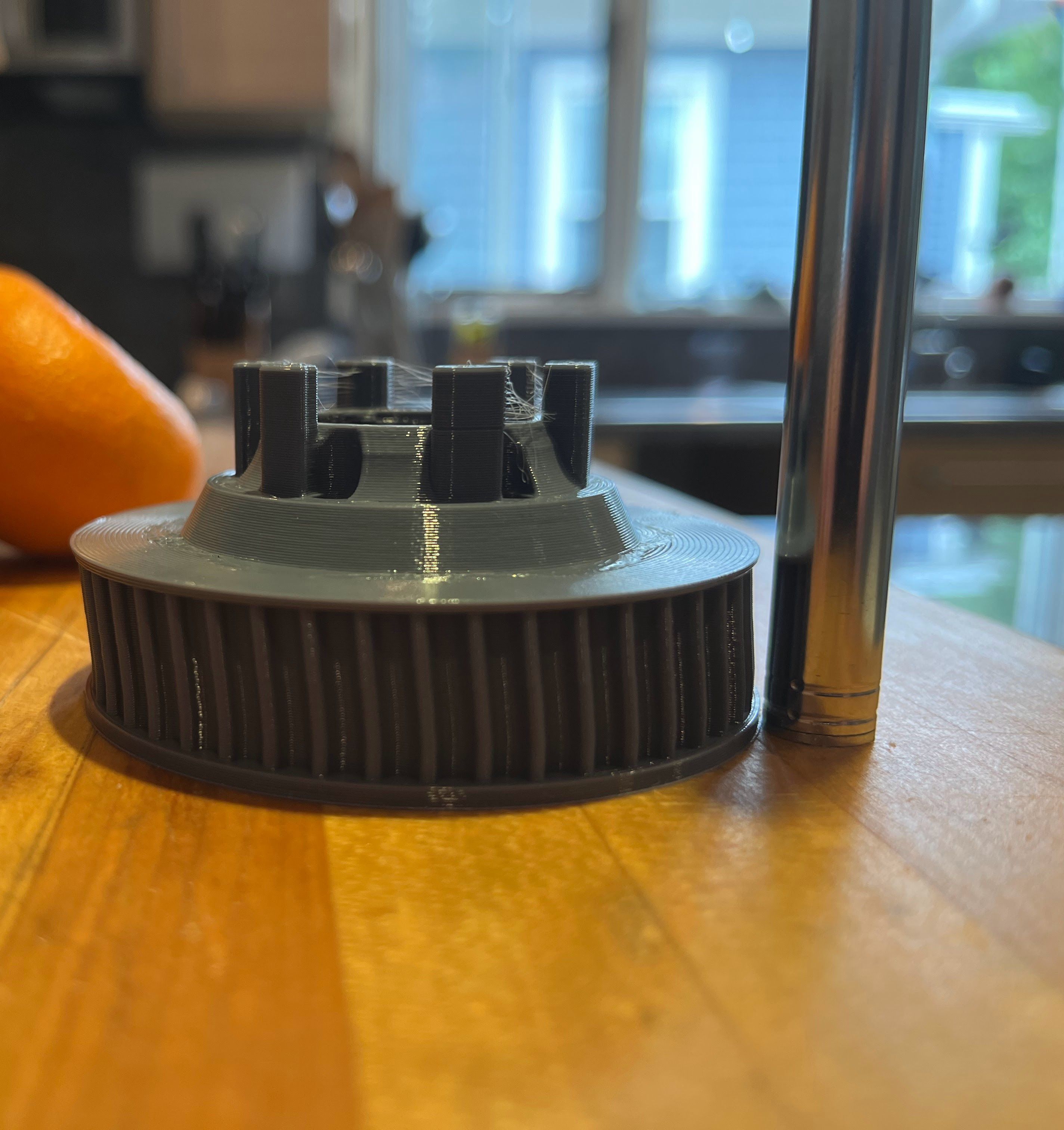
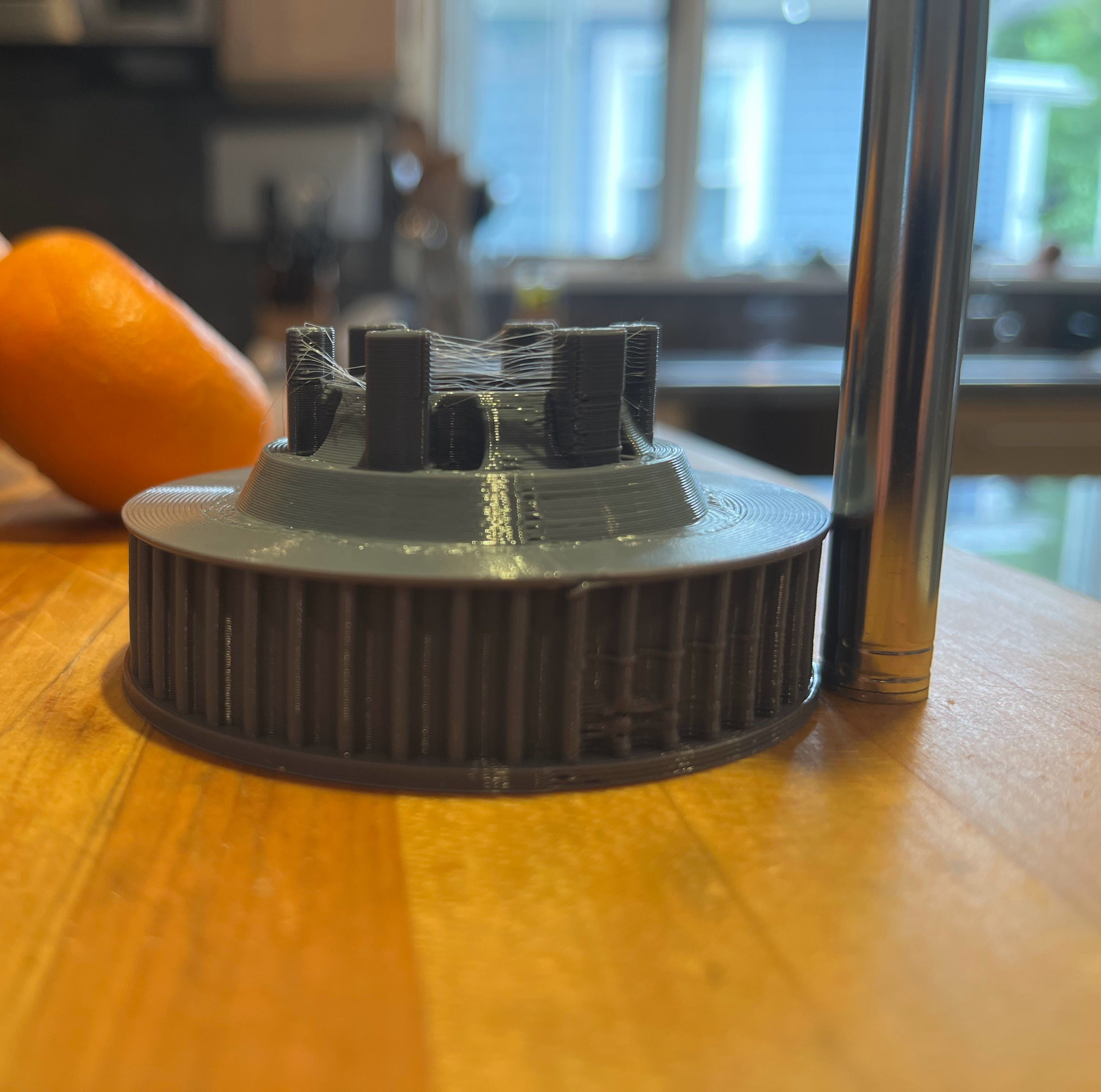
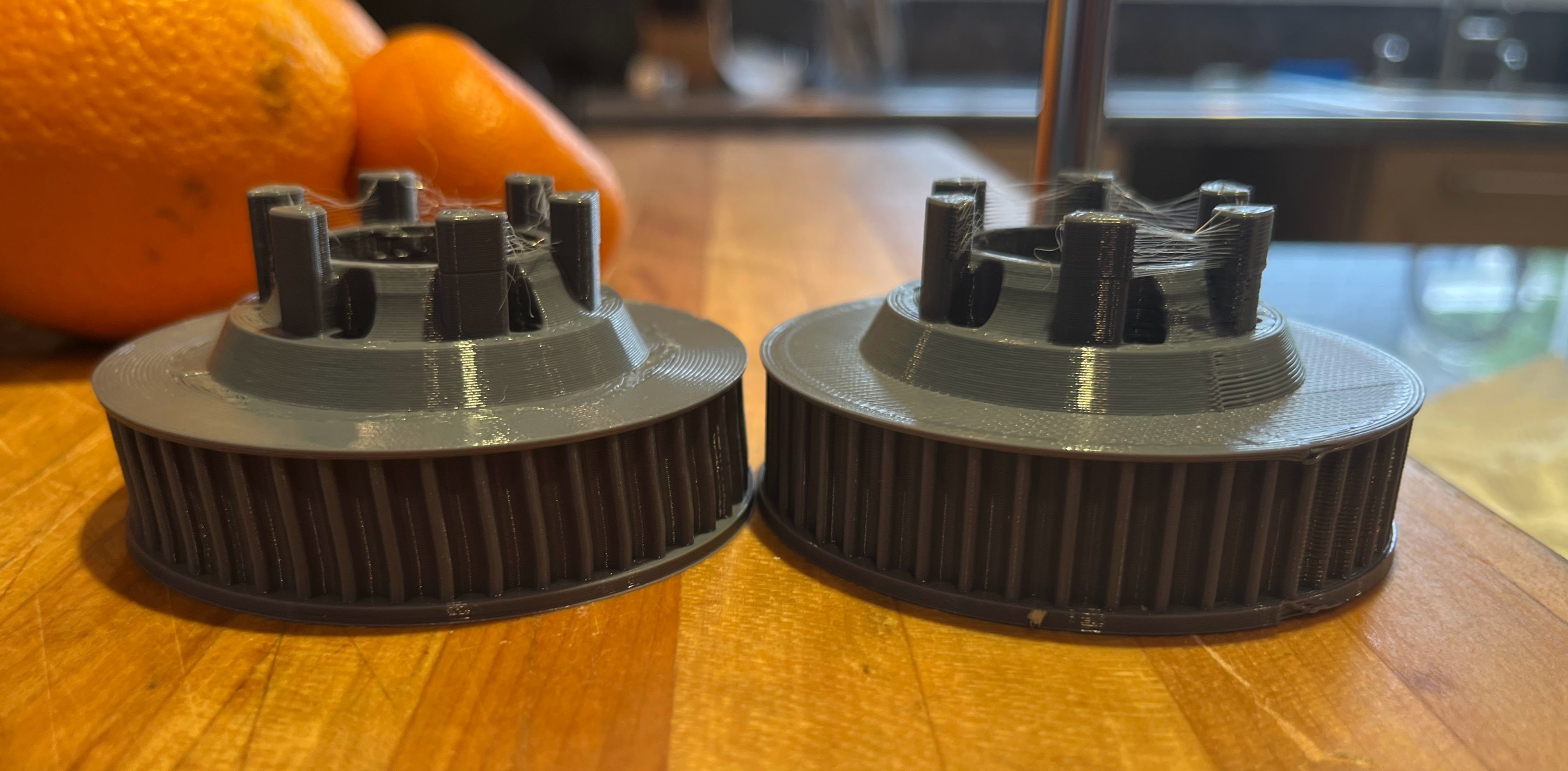
Could very well be. The green material was eSun ABS+, and I printed these black items with Polymaker ASA (same exact gcode).
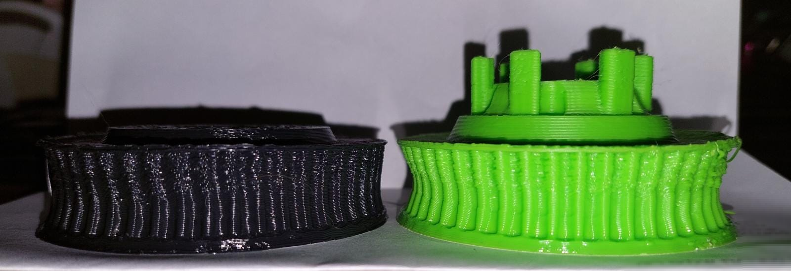
The deformation is noticeably smaller, leading me to believe plastic shrinkage may be the main mechanism here.
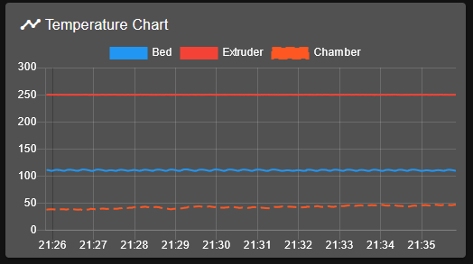
My printing temps:- Extruder 250°c
- Bed 110°c
- Chamber (passively heated by 2000w bed heater) ~40-50°c (rises during the print)
@norder said in Mushrooming print - What could cause this?:
At first glance it looks like over-extrusion or wrong Z-axis stepps.
The retract doesn't seem to be there either, if you look at the blobs on the skirt and where you move from the skirt to the first layer of the component, the filament runs through without interruption.Thanks for calling attention to that. I have a super long bowden tube (>1000mm), and retraction is currently set to only 8mm. I think it's very likely it needs to be much larger to account for the extra length of the filament snaking around in the capricorn tube.
Regarding your calibration suggestions, I am jotting down a list here:
- Check drive item tightness (including pulley set screws in all 4 steppers)
- measure axis travel (all 4 steppers)
- Bed level sensor repeatability test
- Check flatness of travel to bed after mesh probing using an indicator that clips on the effector
- Calibrate flow from scratch (filament diameter + flow calibration print)
- Optimal printing temperature test (temperature tower?)
Will report back the results
@o_lampe said in Mushrooming print - What could cause this?:
How about the rod-distance? The effector looks like the magnets are arranged in a regular pattern (more or less)
It seems easy to match the wrong pair of magnets, which would lead to non-parallel rods.You are correct that it is easy to get a mismatch pair, but in this case it is correct - Thanks!
@norder said in Mushrooming print - What could cause this?:
Did you use the printer to print the red fan-duct that you can see in the photo here ?
Yes
@norder said in Mushrooming print - What could cause this?:
This effect can also be seen there, that the outer wall collapses inwards.
But it seems to be worse on the left side than on the right !?Good eye, I didn't catch that!
@norder said in Mushrooming print - What could cause this?:
Print a 100mm high cylinder (or even higher) in vase mode and show us the result.
It is best to do this in different places on the print bed one after the other.
For example, as close as possible to each of the three Z-axes and once in the middle.
Just to make it clear where this effect occurs.In progress now, will update soon, including results of the above tests.
I would like to say thanks to everyone pitching in to try and figure it out, much appreciated!
-
@leav said in Mushrooming print - What could cause this?:
Could very well be. The green material was eSun ABS+, and I printed these black items with Polymaker ASA (same exact gcode).
The deformation is noticeably smaller, leading me to believe plastic shrinkage may be the main mechanism here.
I can't imagine with the best will in the world that it's due to the shrinkage factor of the filament, sorry.
I printed a shrinkage test for each filament I use (large cross, 150mm x 150mm with a height of about 5mm, since my calliper can only measure up to 156mm) and after cooling down I measured the length of the cross and calculated the shrinkage factor.
You can then enter this value in the slicer and the component will then be printed enlarged by this factor.
But this value is not so high for all filaments that collapsed walls could arise as with your printouts.All axes of my printer were also measured with calipers.
I attach the caliper to the linear rails with a strong magnet and let the print head or print bed move very slowly against the caliper until it moves a few mm, then set the caliper to zero and then let it move 100mm very slowly.Therefore, the calculated shrinkage values are very accurate and agree with the later measurements.
No matter which filament I print... if the stl says one side is 27mm long, then the printout is also 27mm (+- 0.1mm).
The +-0.1mm is then due to the flow, which I find difficult to set exactly.
If the measured wall thickness is correct for calculating the flow, then you may not like the stability of the component and you are happy to add a little more.
What's the point of a beautiful component if the stability suffers as a result.
You have to die a death here!?
Therefore, I would want to rule out such extreme shrinkage in your prints.
My guesses...
The unattractive / unclean print image is due to incorrect values for the flow, retract and possibly also incorrect printing temperatures, with the temperature playing a smaller role here.
The stepps could also not be set exactly, so the Z10 entered in the DWC, measured maybe 9mm.For me, the tapering of the sides is more of a mechanical problem like rods of different lengths or a frame that is not at an exact angle or a loose component or something like that.
And this inaccuracy in the construction makes the already poor print image even worse.As I said... a guess on my part.
I am very excited to see the photos.

P.S.:
Is it s.Wide Angle or are the two gears wedge-shaped?
The black gear has the left side higher than the right and the green gear is the other way around.Google Translate
--- Original Text ---Ich kann mir beim besten Willen nicht vorstellen das es am Schrumpffaktor des Filaments liegt, Sorry.
Ich habe für jedes Filament welches ich benutze einen Schrumpftest gedruckt (großes Kreuz, 150mm x 150mm mit einer Höhe von etwa 5mm, da meine Schieblehre nur bis 156mm messen kann) und habe nach dem abkühlen die Längen des Kreuzes genauestens vermessen und den Schrumpffaktor berechnet.
Diesen Wert kann man dann im Slicer angeben und das Bauteil wird dann um diesen Faktor vergrößert gedruckt.
Aber dieser Wert ist bei allen Filamenten nicht so hoch das so eingefallene Wände entstehen könnten wie bei Deinen Ausdrucken.Alle Achsen meines Druckers wurden auch mit der Schieblehre vermessen.
Ich hafte die Schieblehre mit einem starken Magneten auf die Linearschienen und lasse den Druckkopf oder das Druckbett sehr langsam an die Schieblehre fahren bis sie wenige mm bewegt wird, stelle dann die Schieblehre auf Null und lasse sie dann sehr langsam, sich 100mm bewegen.Daher sind auch die errechneten Schrumpfwerte sehr genau und stimmen mit den späteren Messungen überein.
Egal welches Filament ich drucke... sagt die stl eine Seite ist 27mm lang, dann ist der Ausdruck auch 27mm (+- 0,1mm).
Die +-0,1mm liegen dann am Fluss, den ich schwierig finde exakt einzustellen.
Stimmt die gemessene Wandstärke um den Fluss zu berechnen, dann gefällt einem vielleicht die Stabilität des Bauteils nicht und man gibt dann gerne mal ein wenig mehr dazu.
Was bringt mir ein schönes Bauteil wenn die Stabilität darunter leidet.
Einen Tod muss man hier wohl sterben !?Daher würde ich ein so extremes schrumpfen bei Deinen Drucken ausschließen wollen.
Meine Vermutungen...
Das unschöne / unsaubere Druckbild ist auf falsche Werte für den Fluss, Retrakt und eventuell auch falsche Drucktemperaturen hinzuführen, wobei die Temperatur hier eine kleinere Rolle spielen.
Die Stepps könnten auch nicht exakt eingestellt sein, so das Z10 im DWC eingegeben, gemessen vielleicht 9mm ergibt.Das sich verjüngen der Seiten ist für mich eher ein mechanisches Problem wie unterschiedlich lange Rods oder ein Rahmen der nicht exakt im Winkel steht oder ein lockeres Bauteil oder so etwas in der Richtung.
Und diese Ungenauigkeit der Konstruktion verschlimmert dazu noch das eh schon schlechte Druckbild.Wie gesagt... eine Vermutung von mir.
Ich bin gespannt auf die Fotos.
P.S.:
Liegt es am Weitwinkel oder sind die beiden Zahnräder Keilförmig ?
Bei dem schwarzen ist die linke Seite höher als die Rechte und bei dem grünen Zahnrad ist es anders herum. -
Thanks for the STL files.
I saw that you are using all perimeter features for your infill, so I sliced using Simplify3D and set perimeters to 30.
I also printed "outside-in".
And...........
I got a strangely distorted print!!!
It's not the same as yours, mine looks fine vertically and does not have the shrinkage your does, but mine leans to the left quite a bit.
This is VERY strange as my printer has produces nice (not perfect, but darn-nice) prints for years.
I suppose this could a layer-shift, but since a Delta printer doesn't have layer-aligned axis it's kind of hard to tell. The thickness of the pulley varies from 18.3mm to 18.6mm but that's only 1 layer, so I'm not sure.
I resliced with three perimeters and I'm printing now, so I'll post results in a few hours.
This looks like some kind of print shrinkage due to nonuniform cooling to me. There might be a breeze in my room due to a window being open on one side of the room and a door on another side.
I'll post results later today.


-
OK, so the one I printed using 3 perimeters printed perfectly.
The pulley height is 0.75 inches as I expect you intended it to be.
My conclusion is that when you slice with the interior being "All perimeters" rather than infill that differential cooling causes massive distortions.
Can you try reslicing with three perimeters and something like 42% (more or less
") ) infill and see what you get?
) infill and see what you get?

-
If it helps, this is the recommended setting for Voron parts, some are structural and some are for the look.
- ABS
- Nozzle: 0.4mm
- Layer height: 0.2mm.
- Extrusion width: 0.4mm, forced.
- Infill percentage: 40%
- Infill type: grid, gyroid, honeycomb, triangle, or cubic.
- Wall count: 4.
- Solid top/bottom layers: 5.
- Supports: NONE.
Not mentioned but I also run the material cooling fan low.
-
in my humble opinion, this is a combination of issues, like others said.. temps seem too hot, over extrusion maybe..
BUT none of that explains the absolutely incredible geometrical deviation from your design. This is not shrinkage lol, not in this way, not in such amounts. And then it switches to reverse-shrinkage? heh...
If it was bowden related, you would expect similar defects within each layer, not a continuous geometry change over many layers.
I have a sneaking suspicion, that something is screwed up with the geometry settings of your delta. Arm length in the FW perhaps wrong.. anything related to M666 and M665
Do you have a log of what you did to the machine? Was it working well before your changes?