My DIY Maestro powered Bed-Slinger (many photos inside)
-
Hi all,
I'd like to present to you my self-designed, own built printer that has been conceived and created over a year ago.
Short overview:
-
Duet Maestro mainboard
-
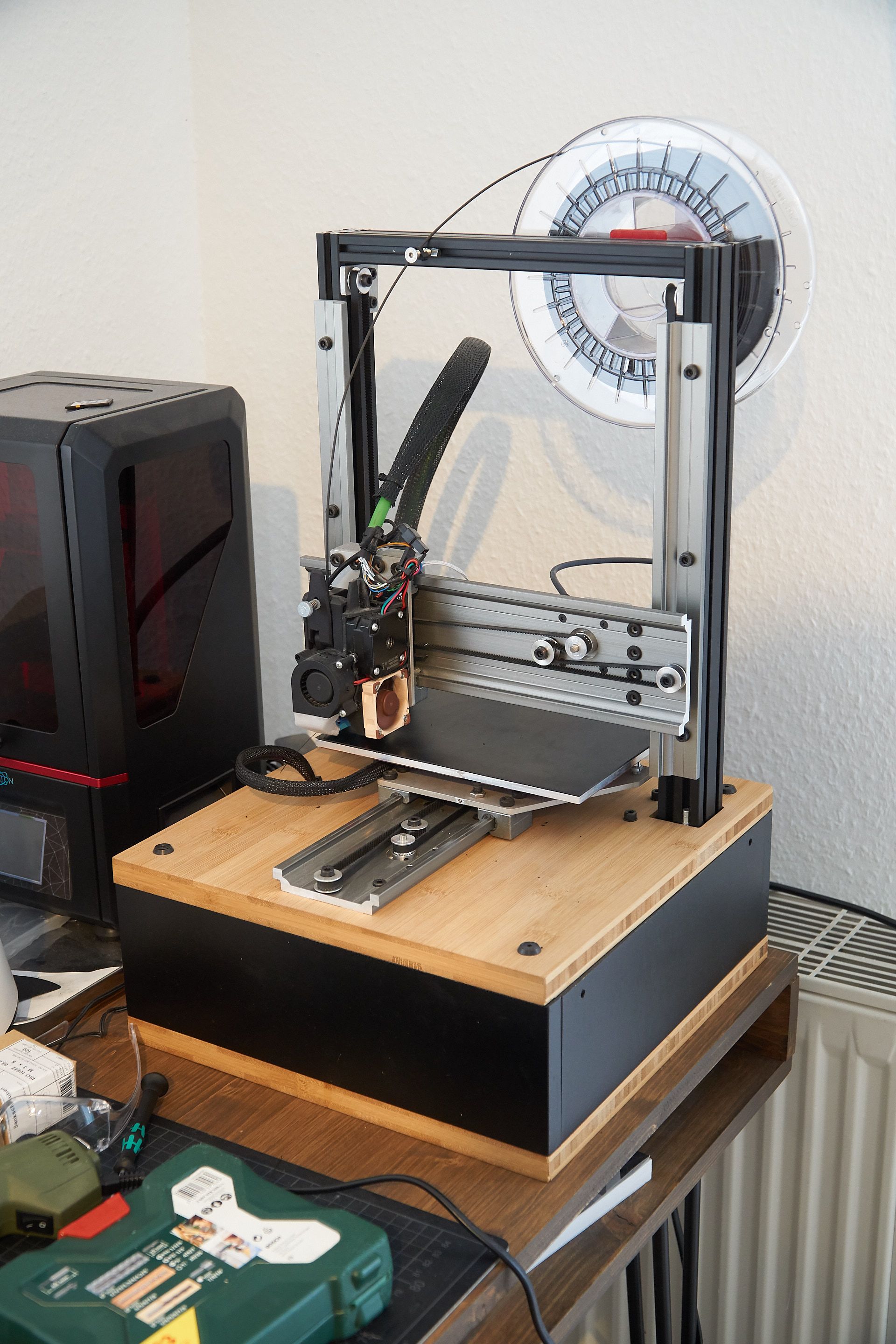
genuine E3D v6 gold hotend (why yes, I do consider myself a fancy individuum), mounted to a genuine Bondtech BMG with a 0.9° 1.2 A stepper motor from Stepperonline (17HM08-1204S)
-
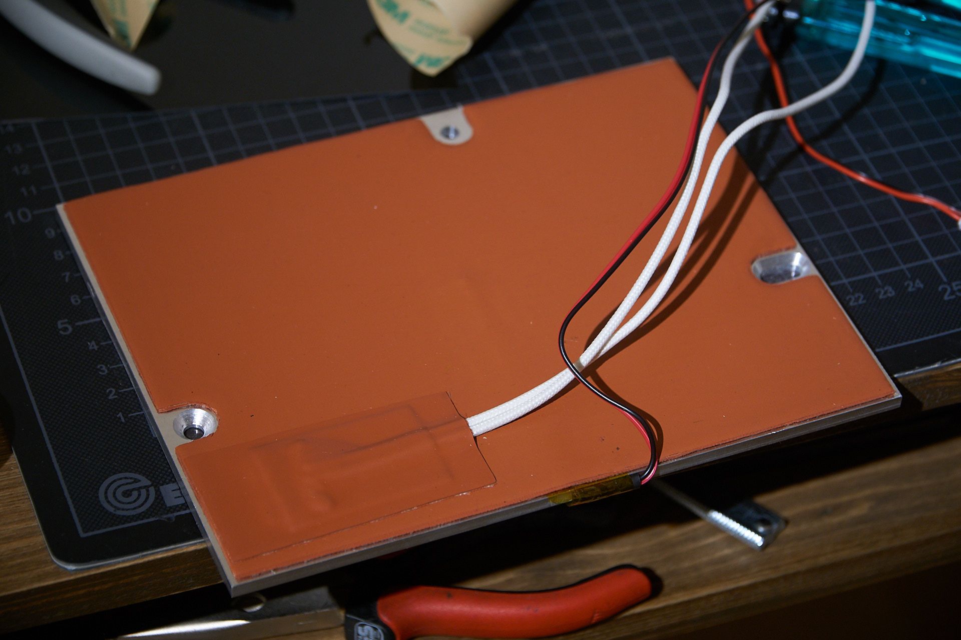
custom 160 x 210 mm heatbed (5 mm cast aluminium) with custom 200 W 24 V silicone heater with a PT1000 temperature sensor, powered directly by the Duet
-
highly integrated motion system based on igus Drylin W linear rails (6 mm square profile, more on that later), belts on all axes, driven by About3D (RIP) 1.8° stepper motors
-
optical endstops for y (x not implemented yet), BL-Touch for bed leveling
-
black 2040 extrusion frame with bamboo base plates
-
Separate 5 V and 24 V power supplys by Mean Well, the 24 V supply is switched by M80/M81 via relais
-
all of the wiring is hidden in the mysterious black box that makes up the base of the frame. It's connected to the network so it doesn't need an own control interface, however I will propably dedicate an old smartphone as a seperate touch screen to control the printer when the PC is off.
Some of you might find the design somewhat familiar; the use of the Drylin linear rails in the way that I did it was inspired by the Protoworx Tiny, which is a precious little machine that is capable of some very nice prints when it's properly set up. Check it out here. I'm not affiliated with the creators, but I felt it necessary to mention the design because credit is due. I did however route the belts very differently.
some pics of the build process:
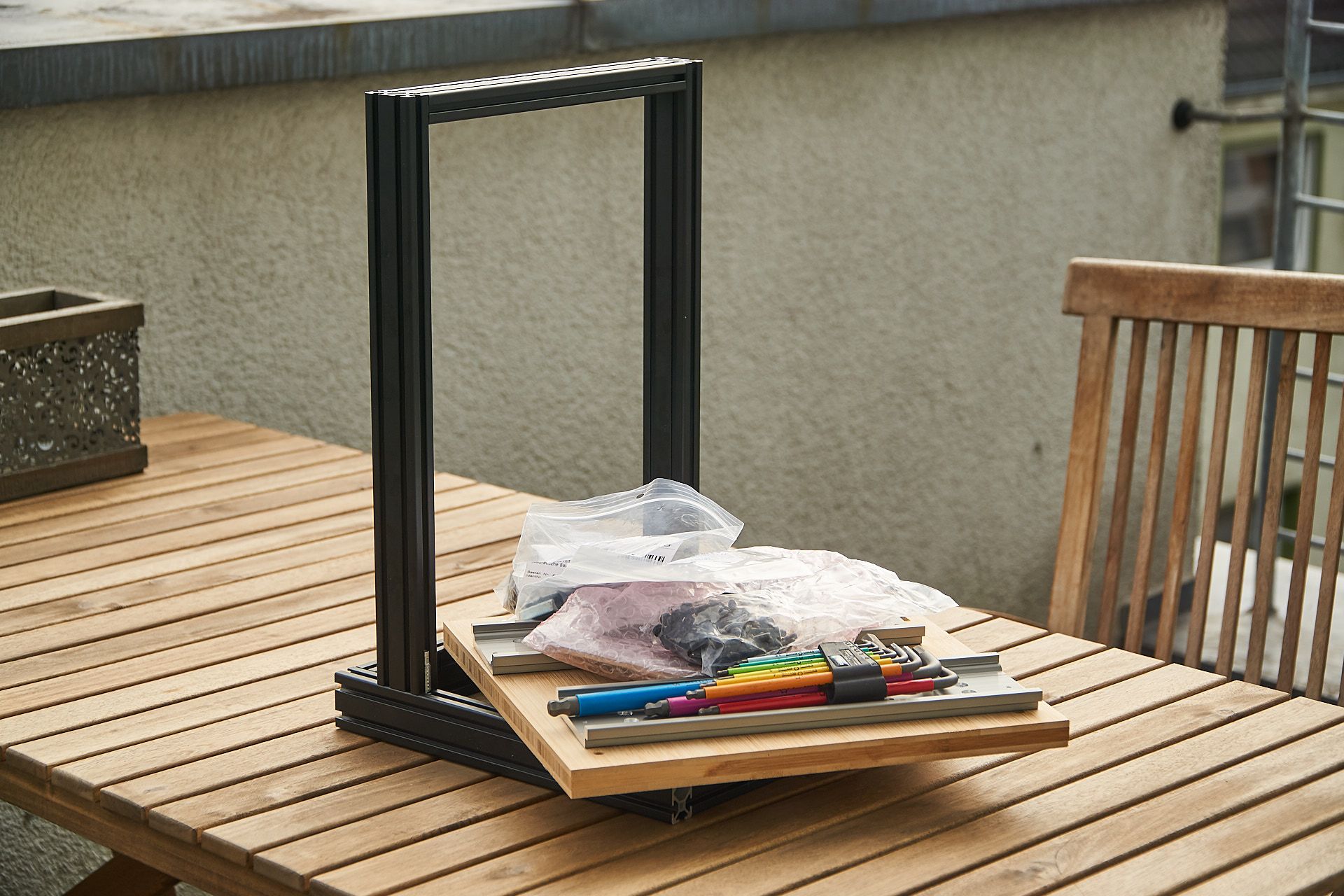
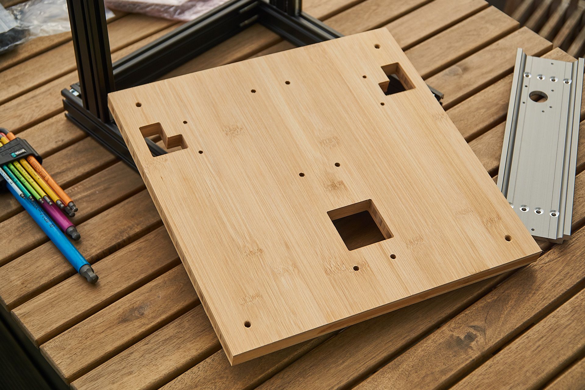
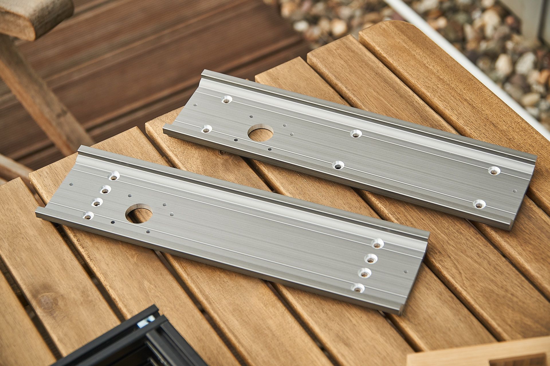
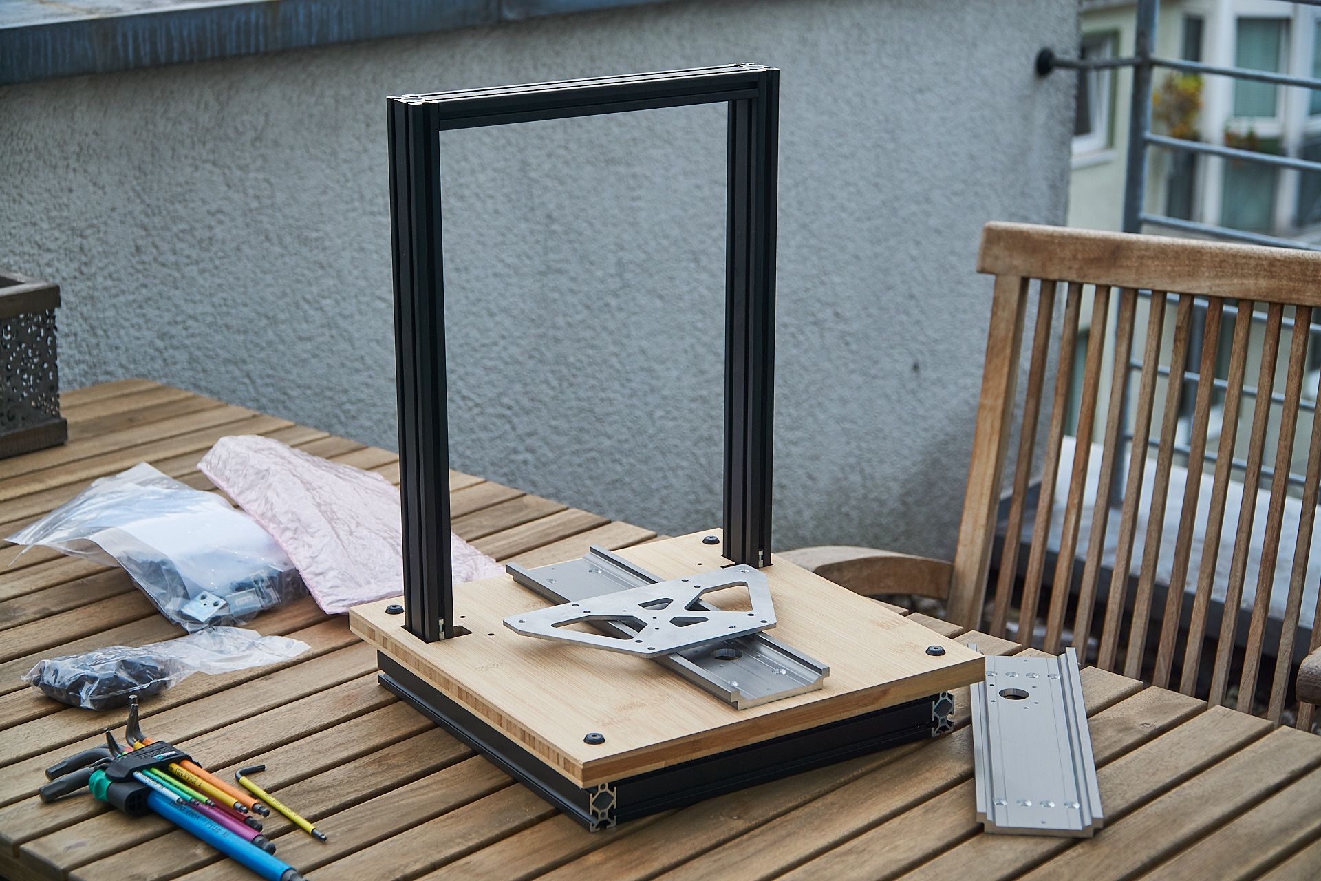
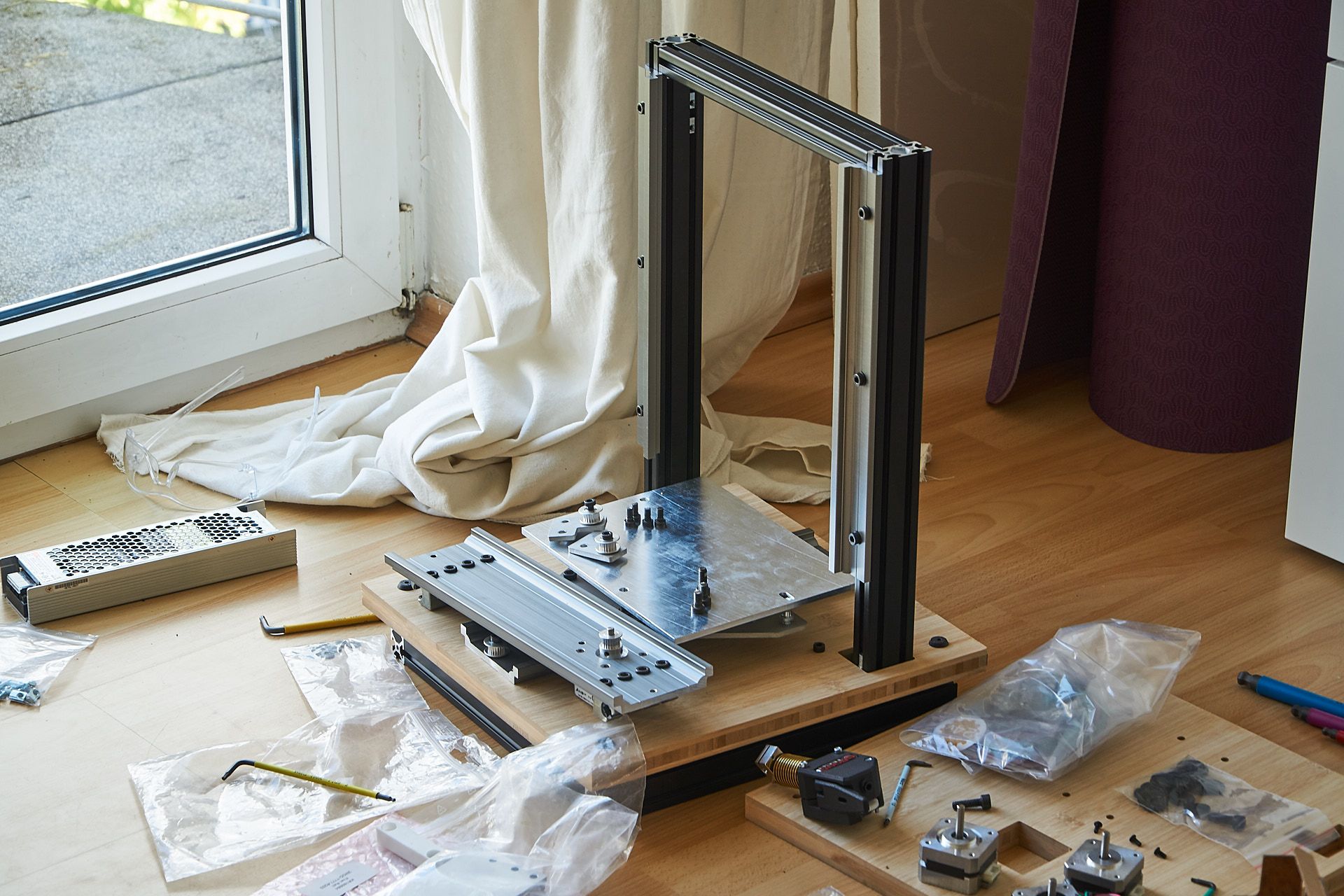
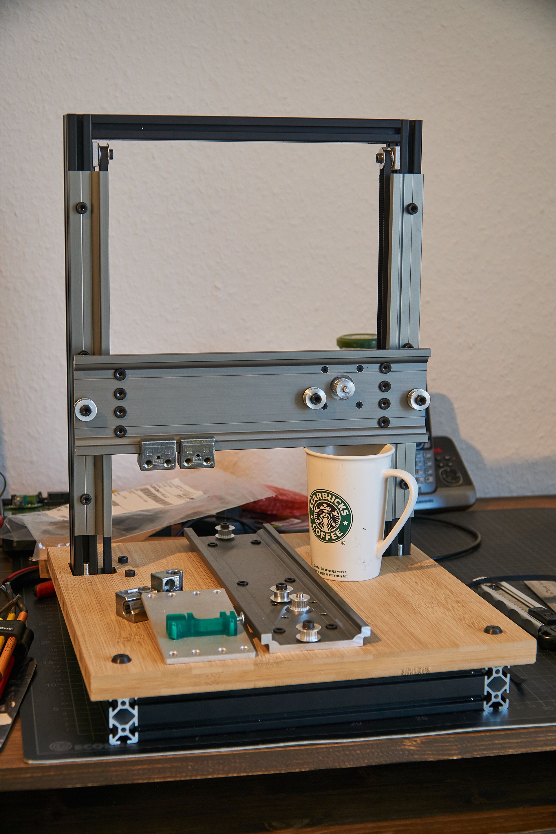
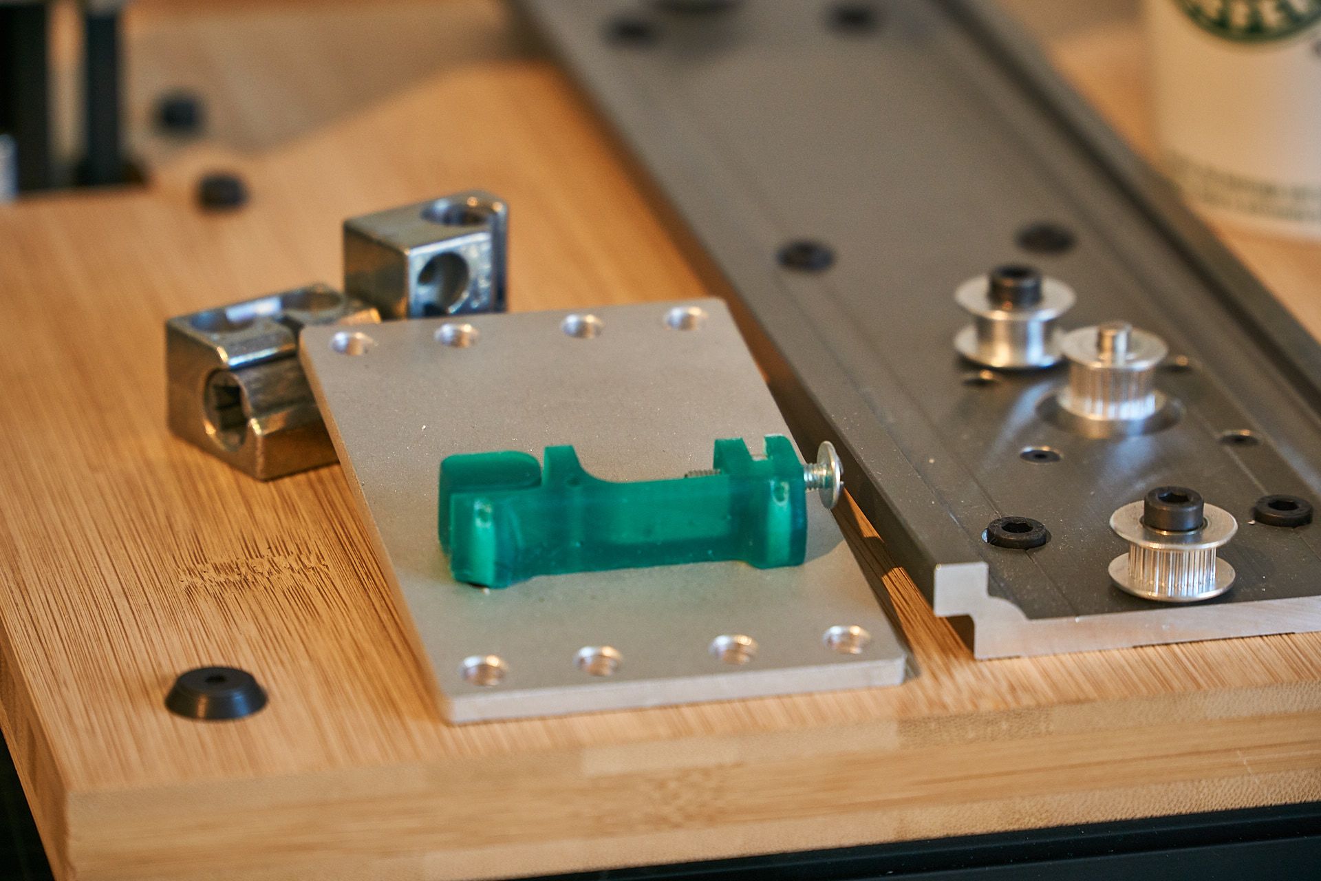
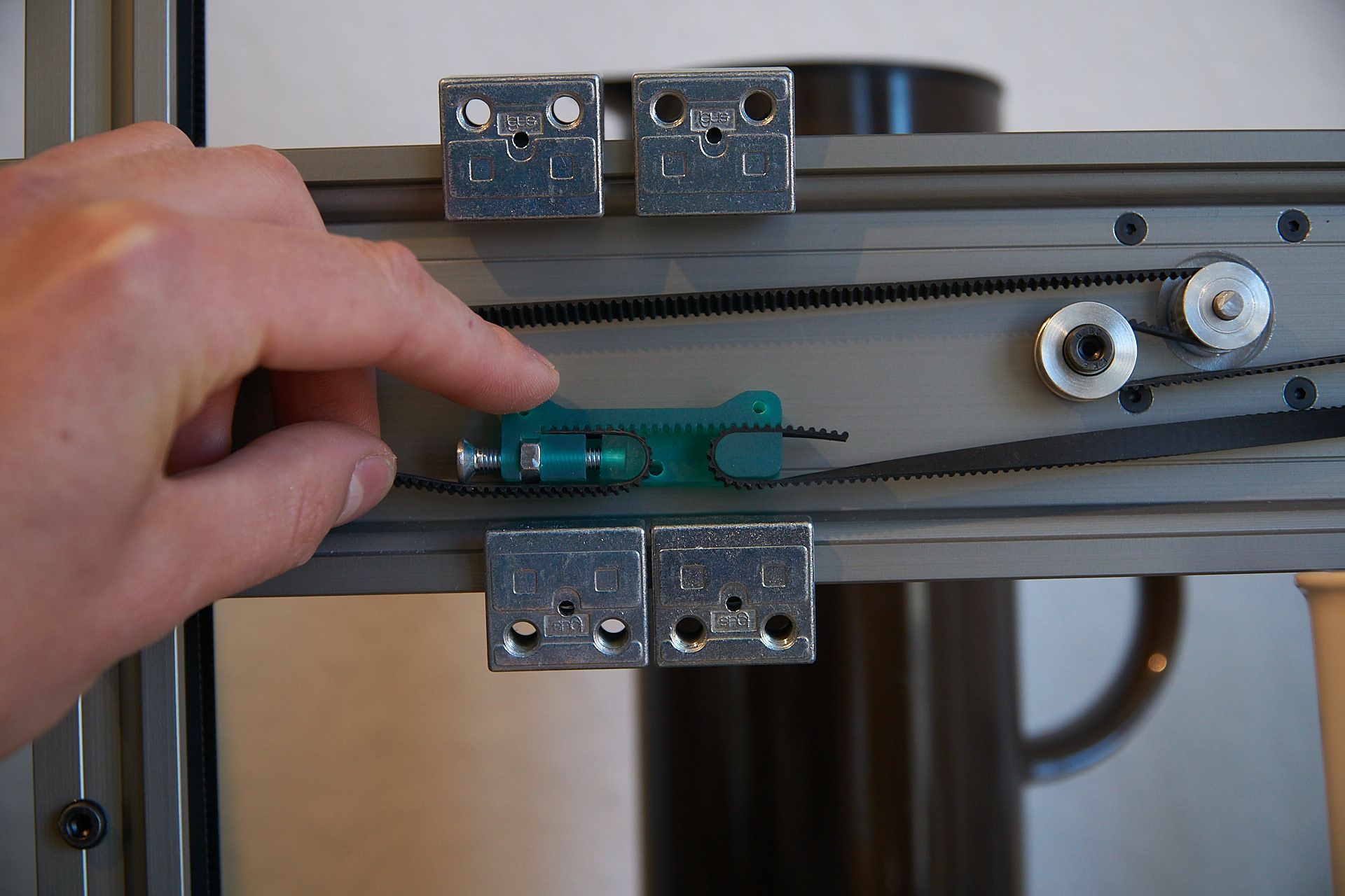
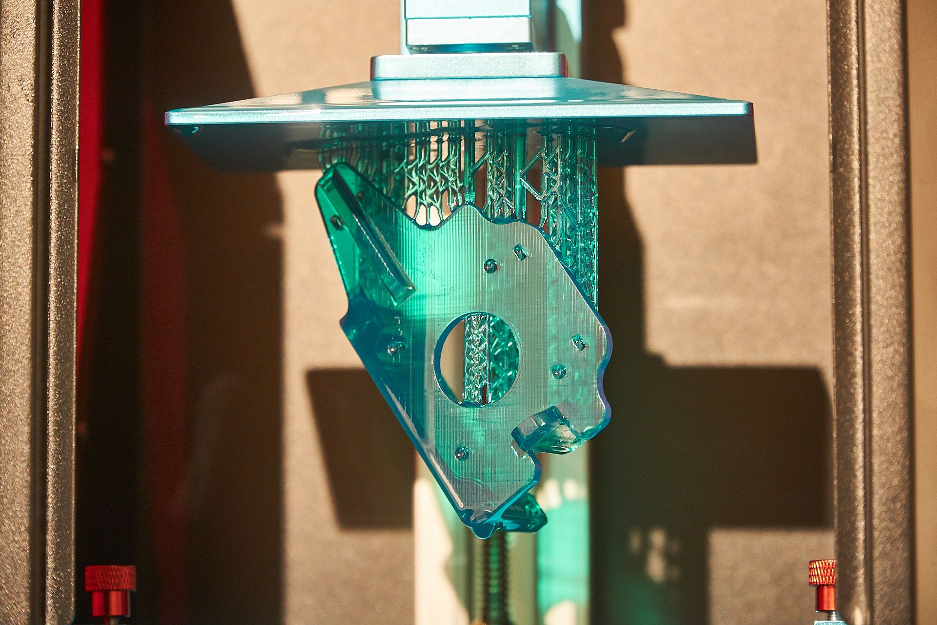
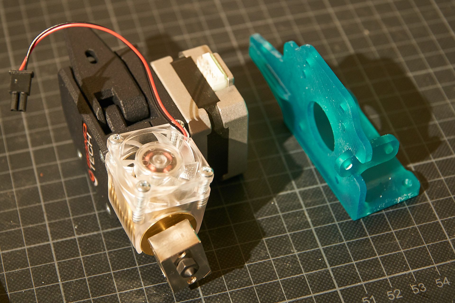
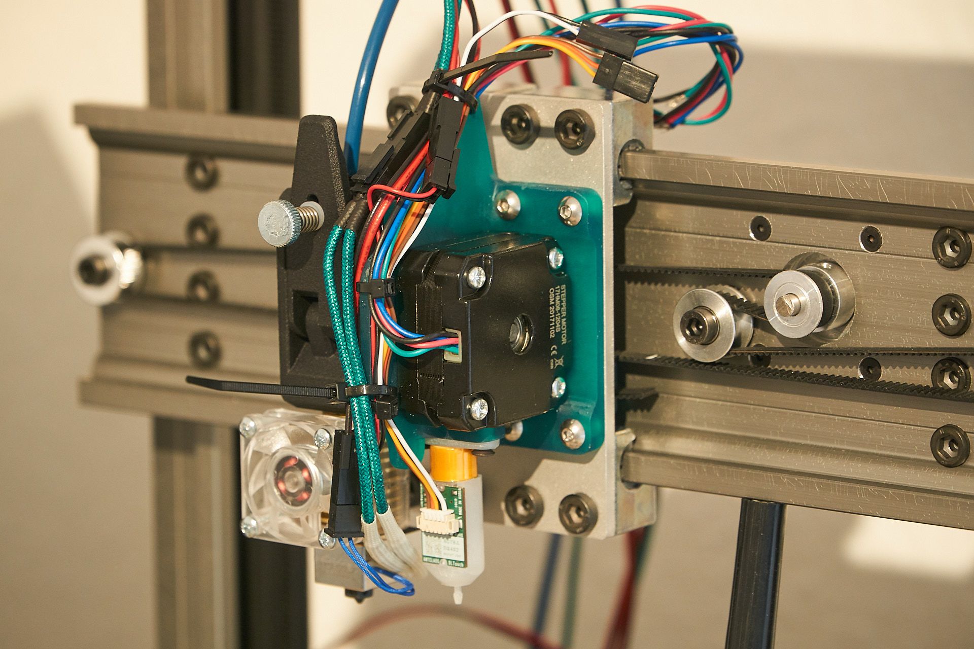
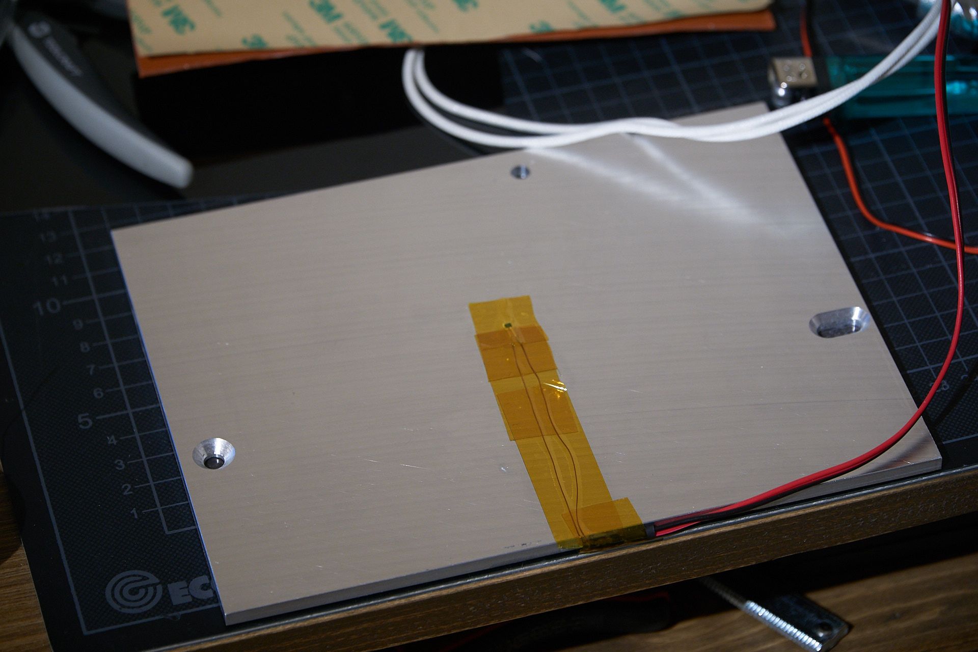
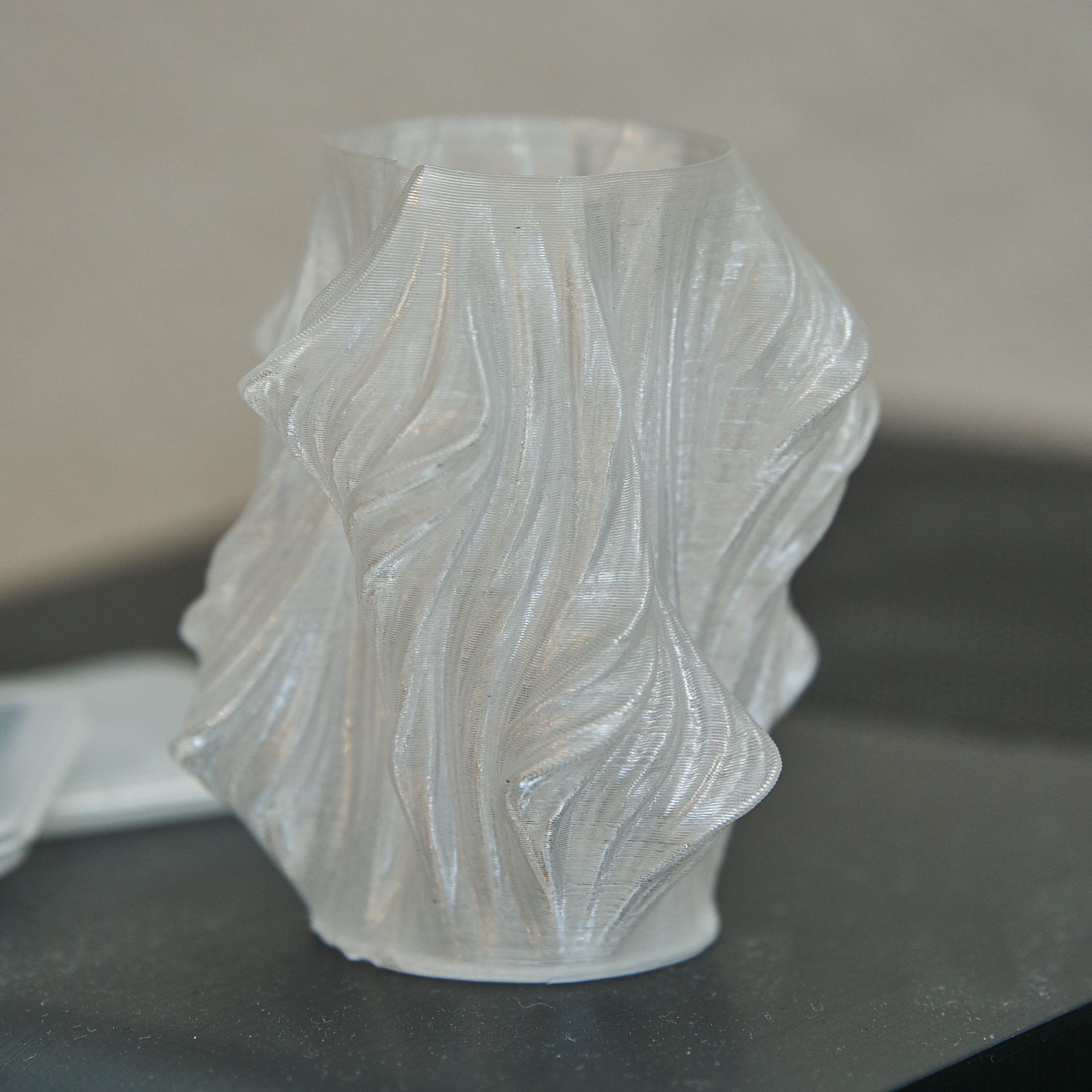
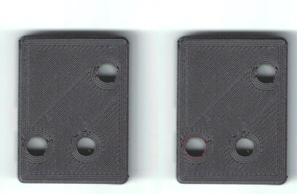
itsy bitsy sample print:
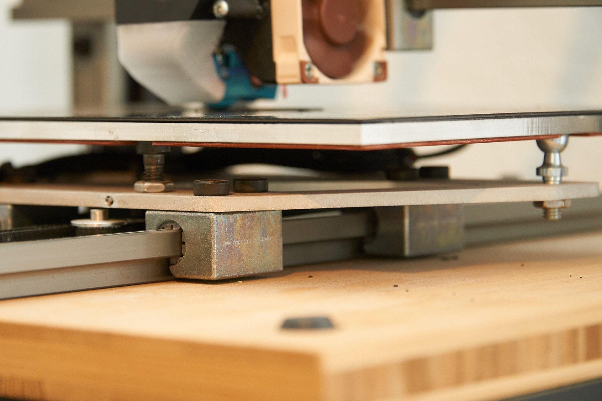
The hotend mount has been upgraded to mount a 40 mm Noctua fan for absolutely silent operation. The heated bed is "mounted" (read: laid down) Mark Rehorst style on two ballhead screws and a flathead screw. There should be springs holding it down, but you can see the tip of the broken thread tool still sticking out of the base plate from whence this operation failed and the motivation left me to fix it permanently. It works at low-ish speeds due to the weight of the cast aluminium plate, but you can hear it flapping around a bit when it moves to quickly.
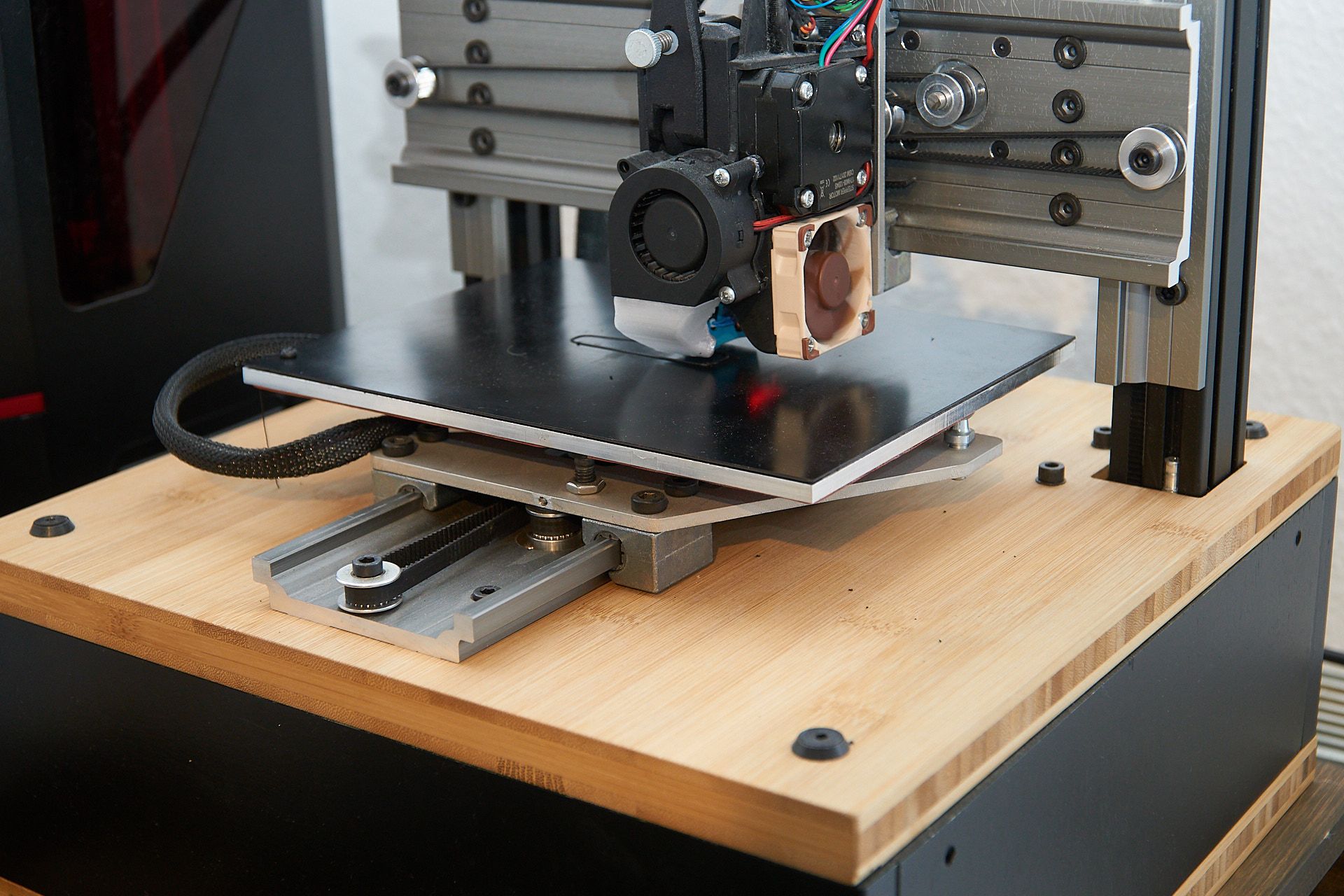
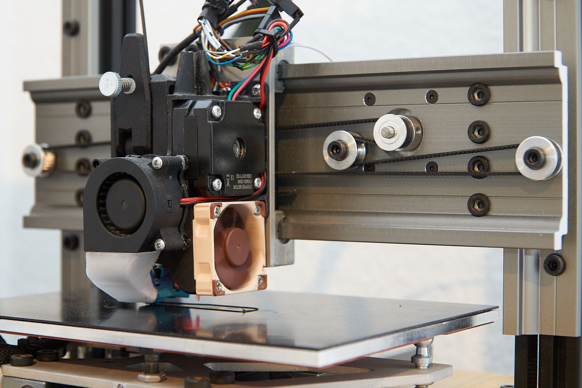
The bed surface is actually quite nifty, I bought plain black PEI sheet from a german distributor, and glued it to magnetic foil that is temperature stable to >100 °C. This "foil" is rather flexible but is held down to the build plate quite strongly. I haven't worked with warp-heavy materials though, there I would deem it possible that the part lifts this foil off the bed. I might also look into getting a spring steel sheet that would work better.
So this is the printer as it exists up until now, but won't for much longer. At the moment it's printing parts for its next big upgrade. I'm using Colorfabbs XT-CF 20 filament for structural parts, which seems to yield very strong parts yet is somewhat easy to print.
In the next post I will explain the upgrades that are going to happen to this machine, which will for the most part change its appearance radically. I'm ditching the igus Drylin rails - not because Drylin isn't suited for 3D printers, but because I chose the wrong type (I have to say this, because I work at igus and am somewhat a fan of the components).
I hope you enjoy this thread, I will post updates here on the remodelling that is happening, and show some sample prints once it's done.
oh yes: @wilriker you were interested.
Best regards, Niklas
-
-
@sonderzug said in My DIY Maestro powered Bed-Slinger (many photos inside):
because I work at igus
what a terrible combination with such a hobby!:D
-
Hi Niklas,
Schöner Aufbau!
Any particular reason you put the stepper for the X axis in the middle with another idler instead of one side?Viele Grüße,
Max -
It was great to meet at Formnext and I like what you have done with this printer!
-
Hi Max,
the goal was to have all of the components inside the 30 cm cubed frame with none sticking out on the sides. Not definitely a must have but I think it's a rather elegant solution (again copied off the Protoworx printer).
For my upgrade this design will also allow me to only use plain ball bearings instead of toothed idlers which is a win in my book.
Tony, it was nice meeting you at the fair! Thanks for the compliment, and there is more to come!
-
I've broken taps in plates before. Ouch! There's no good way to get them out short of using a hole saw to cut around them. Was that a custom heater or did you mill/drill the plate to match the heater you had?
Are the bearings in the linear guides adjustable?
It looks like a solid build...
-
Broken taps can be removed with an EDM setup. Probably $50 to have it done but of course you need to remove the bed fro the printer.
-
Can you post some more photos of the Z axis arrangement? I see it's belted, but can't see much else.
-
Hi everyone,
thanks for the replies. The tap end is stuck there for sure, but it's not a big problem as 1) the position of the spring is variable as long as it's in the proximity of the respective support screw and 2) I have a second base plate left over. The only slight nuisance was that I had to go back to the hardware store to get another M3 tap.
@mrehorstdmd ,
the heater was custom made to my drawing. I had every component (well, the critical ones) designed before I ordered the first part for this build.
the bearings are not adjustable, which is my big concern with these rails. That's the wrong choice I was referring to earlier. The Drylin W rail is also available with round guides (which is actually the standard variant). For the round rails, there are bearing blocks with pre-tension by spring or screw available.The play in the bearing blocks plus not perfectly tensioned belts lead to backlash which leads to un-round holes (at least that's my theory).
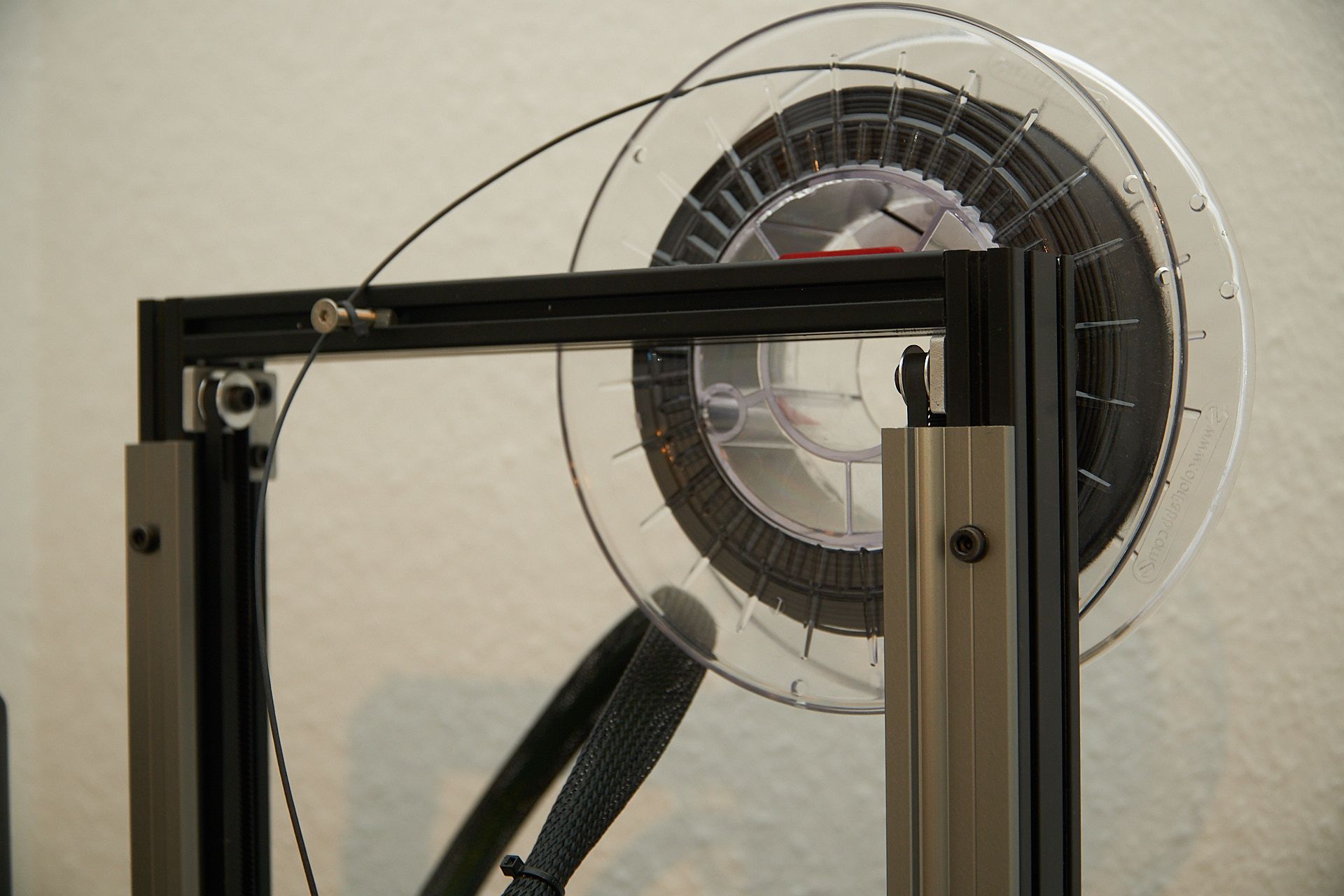
see below the setup of the z axis. There is a 8 mm rod underneath that connects both belts, which is driven by the stepper with a 2:1 reduction for extra resolution and torque. There are standard pulleys on each end driving the belt. There are little idler plates at the top of the frame, which are also used for tensioning the belt by pushing these upward (a screw through the upper frame member would propably be the more elegant solution).
Edit: the obvious disadvantage is that the x-axis drops like a stone when the steppers have no power applied. I'm thinking about a little servo with a lever that will support the x-axis in the upmost position, once the print has finished. Another Idea would be to add a relais that could short-circuit one or two coils of the z-axis stepper motor, which would be controllable by G-Code, with the short-circuited coils having enough holding torque to steady the x-axis. Has anyone tried this? Problem could be that this acts like unplugging the stepper from the board while on, which is a no-go...
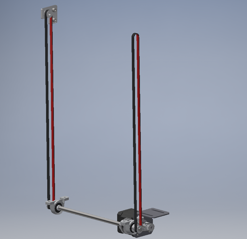
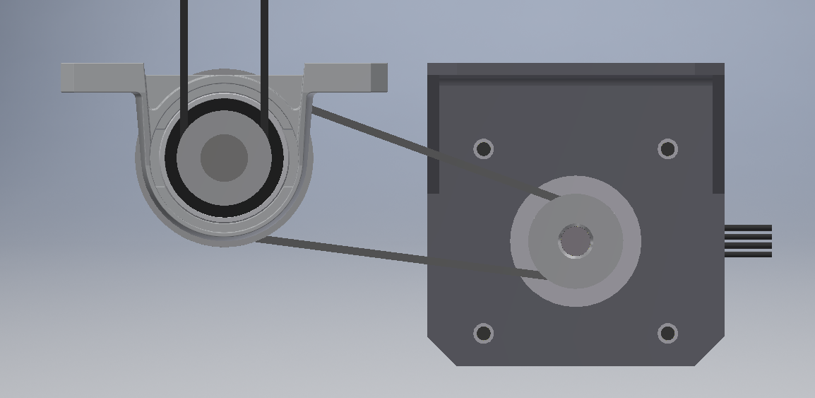

Best regards, Niklas
-
Shorting the coils of the motor will not stop the bed from dropping. There is no current in the coils unless the shaft turns, and the current is somewhat proportional to how fast the shaft turns. I tried it and found that it slowed the drop a little at first, and then the torque slips and the bed drops like a rock (my bed assembly weights 3.5 kg).
Someone at the makerspace used one of this type of motor/gearbox to drive a Z axis and it works well.
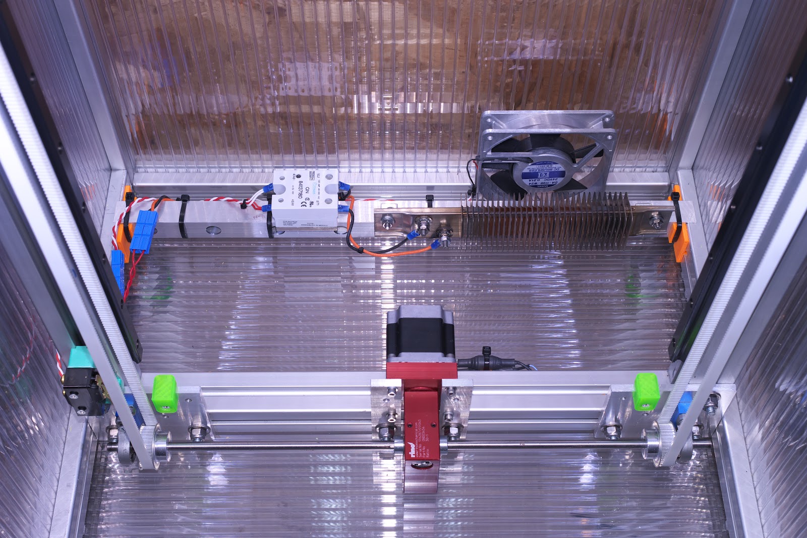
I used a Rino 30:1 worm gear reducer in my printer. The bed doesn't move at all when power is cut, so in theory, I can resume prints after a power failure.
You can buy motors with built in brakes, but they usually cost more than a motor with a gearbox.
You can work up a mechanical arrangement similar to the brake that stops a seat belt from moving in a car. -
Re shorting coils, think the Up! Mini 2 does this with a relay as it will hold the bed in position even if the power fails with the original electronics. When run of the duet the bed falls like a brick when steppers are disabled. But the bed is tiny and the needed holding torque is minimal on the Up! Mini 2, no idea how well it scales but you could try it, and look into disabling the stepper driver just before shorting out the coils if it gets you enough hold.
-
Hi Niklas,
I think your best bet is one of three:
- use a high inductance motor for the Z, they have a very high "turning resistance", I´d call it
- use a higher gear ratio so that your normal motor is OK
- Tension the belts a lot more
(4.) use a nema 23. That will have enough resistance when it is powered off.
Grüße,
Max -
There was a thread about shorting motor coils to ground with a relay a couple of months ago, but can't find it now! Anyone's else's searching-foo better than mine?
Ian
-
@sonderzug said in My DIY Maestro powered Bed-Slinger (many photos inside):
the obvious disadvantage is that the x-axis drops like a stone when the steppers have no power applied.
Counter balance it with some weight? Use a warm gear between the motor and the belt?
-
@bearer Shorting the coils does not stop the motor from turning. There is no current in the coils unless and until the motor turns. If the motor turns, the bed is by definition, dropping.
Without a counterweight, the gears/screws/nuts remain engaged at all times regardless of direction of motion so there's no possibility of backlash. If you unload the gears/screws/nuts by adding a counterweight, you introduce the possibility of backlash.
Here's a belt driven Z axis that does not move when power is cut:
-
I haven't studied the solution employed by tiertime, but it seems the 19v supply for the drivers is either feed to the drivers, or shorted to ground, resulting in the the bed not dropping if the motors are disabled and/or the power is lost; and if it moves a fraction of a 0.9 degree step and stays there then close enough. They do have a power fail resume function, but as it doesn't preheat the machine its of limited use. On the other hand power failure doesn't result in the bed dropping backriving the board with potential "high" voltage.
I'm pretty sure the lost microsteps + theoretical backlash in gears, axle torsion and belt strech is comparable to whatever motion is present on the Up Mini 2 when compared to the overall rigidity of the machine (which on the Up Mini 2 is a joke). Everything moves, not everything matters.
-
It was @smece in this thread https://forum.duet3d.com/topic/12341/e-_endstop-laser-and-rotary-filament-sensors-motor-enable, who was going to...
make small daugterpcb
... using ...
the ENABLE signal I need is the ENN net found on expansion port pin 28, so even easier to access
... to check the motor status and short the coils if turned off. Did he ever do it?!
@mrehorstdmd shorting the coils certainly makes the harder to turn, and has been used on a number of printers to hold the bed at power off. If the weight of the bed does cause the motor to turn still, there may at least be enough resistance to stop the bed "dropping like a stone" and causing damage. So may be an easier modification than redesigning the Z axis. Depends on what the objective is.
Ian
-
@droftarts said in My DIY Maestro powered Bed-Slinger (many photos inside):
... to check the motor status and short the coils if turned off. Did he ever do it?!
yes, works as expected

z motor is not very powerful so with original screw on ender5 it "kinda works" so with the glass off the bed it holds the bed, but barely, if there's a print on the bed it will sometimes slowly start to drop.. maybe glass is too heavy, there are also the big hands stiffening the bed, the precision piezo sensors.. but it holds it from "dropping like a stone" as it did before this mod. I'm now waiting for the new replacement screw (with 1 start compared to 4 starts on original one) and with backlash nut (not required for this use but backlash nut adds additional tension to the screw increasing friction) it will stay still even without this mod and with this mod I believe it will be rock solid. Unfortunately, we had a month of post on strike here so everything is now delayed
 I doubt I'll get the new screw this year.. I will also replace original motor with the .9 degree one as I have few of them but they are high impedance so too slow for anything else so why not use it to increase precission even more :D, Z is slow anyhow
-
If all you're worried about is the bed somehow doing some damage when it drops, almost anything can be used including putting a couple springs at the bottom of the Z axis so the bed will make a soft landing.
If you want to absolutely stop bed motion when power is lost so that you can resume a print after a power interruption, you need either a brake, a worm gear drive, or some other solution that locks the bed in position. A high ratio conventional gearbox (or a series of pulleys and belts) may work if the detent torque of the motor multiplied by the gear ratio is greater than the torque created by the potentially falling mass.
If the bed drops and you want to resume a print, you have to have an accurately calibrated Z ordinate for the bottom of the Z axis. Then you can just move the bed back to the previous Z ordinate and resume printing. It might be useful to use a switch at the bottom of the Z axis.
-
@smece said in My DIY Maestro powered Bed-Slinger (many photos inside):
backlash nut adds additional tension to the screw increasing friction
I think you'll likely notice the 1 start lead screw is more than enough to stop any automatic downward movement. The backlash nut would likely add enough extra friction in that case to allow for easy binding. At least that's what I found with my 1mm pitch single start lead screws. My bed assembly is very heavy and during a power loss there is no movement whatsoever, even when loaded up with several kilograms of filament on the bed. When I first tested the anti backlash nuts the z axis would bind and stall at the start of long travel moves. I had to reduce the acceleration dramatically to overcome that. I gave up on the anti backlash nuts after that.