Duet3D Logo Duet3D
    • Tags
    • Documentation
    • Order
    • Register
    • Login
    1. Home
    2. DigitalVision
    3. Best
    • Profile
    • Following 0
    • Followers 2
    • Topics 6
    • Posts 60
    • Best 23
    • Controversial 0
    • Groups 0

    Best posts made by DigitalVision

    • A Software Solution to Eliminate Ringing?

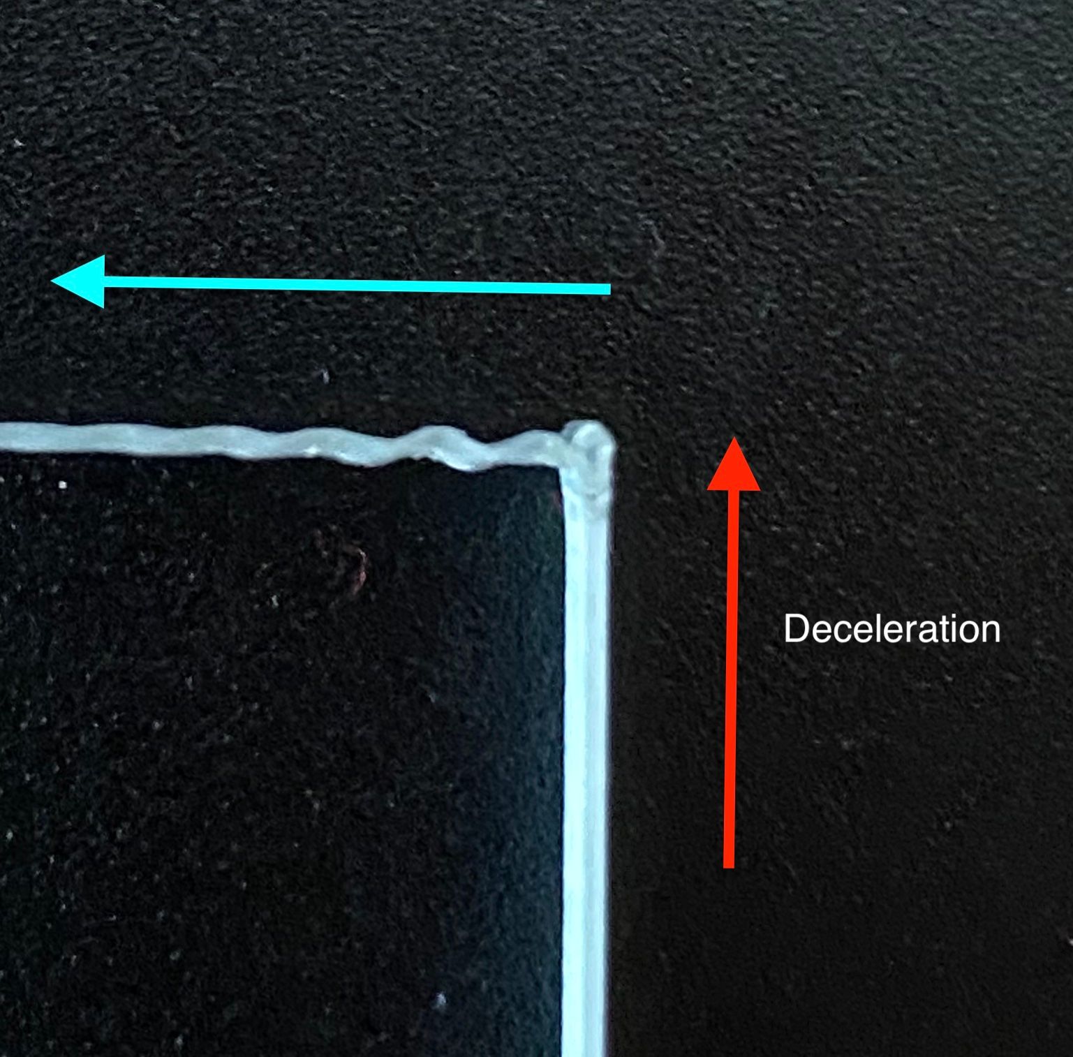
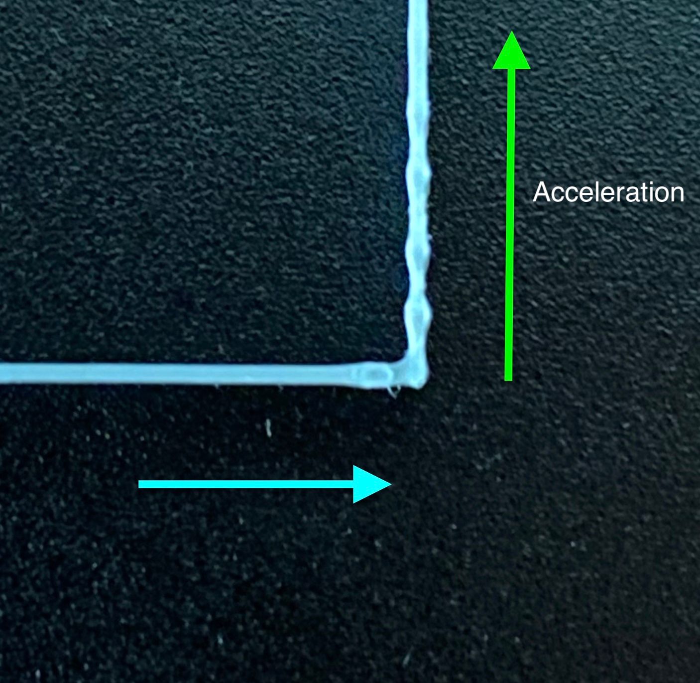
      Some background. One of my 3D printers is a fairly large delta printer (Ultibots D300VS+, ø300mm, 1000mm verticals) with a direct drive extruder (Titan Aero). This printer hasn't gotten much use since the heavy end effector combined with the long motion arms make it very susceptible to ringing and overshooting even at very moderate print speeds.

      One of the key reasons for the lack of rigidity on this specific printer was that the original delta carriers were manufactured in a somewhat flexible material. A few weeks ago, I machined new ones in aluminum, and while this dramatically improved the rigidity and printing performance, ringing was still significant. I contemplated converting it to a Bowden design, but before doing that I wanted to test an idea I've had for a while but never really had the chance to develop: Could we reduce ringing by making the motion control be more aware of the dynamics of the mechanical system?

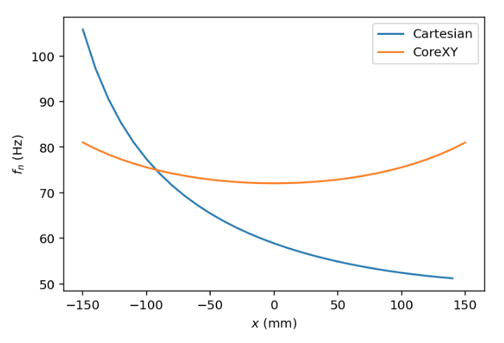
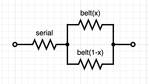
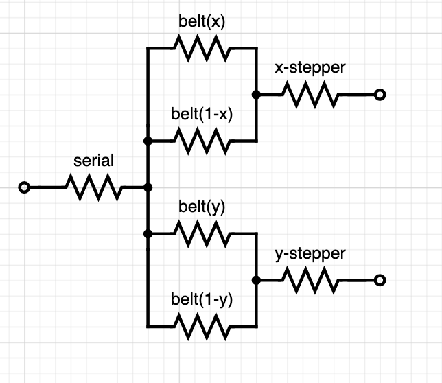
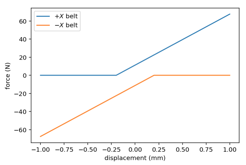
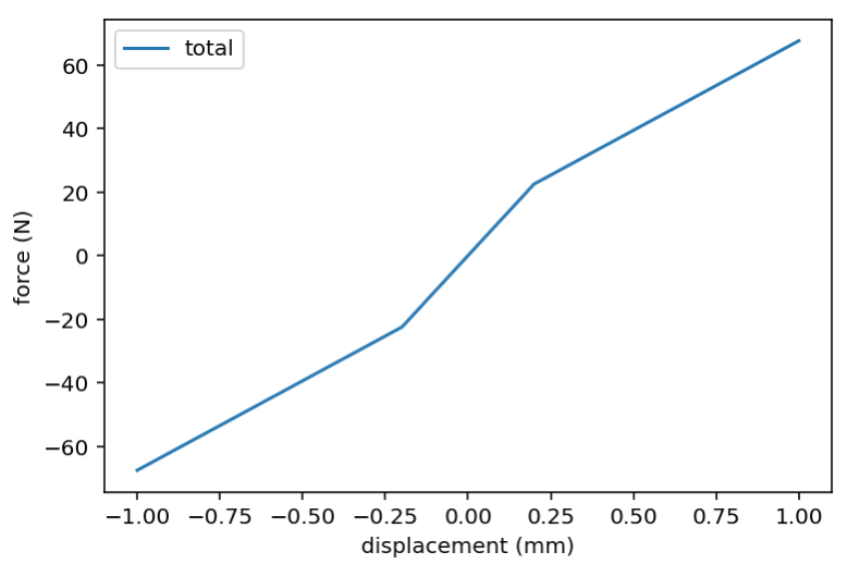
      The general idea is that 3D printer mechanics can be modeled as mass-spring-damper systems, with the "spring" coming from the electrical field in stepper motors, elasticity in belts and the flexibility in other motion components. For deeper discussion and analysis, I did a little bit of modeling and simulation, summarized in this short write-up:

      https://digitalvision.blog/spring-damper-control

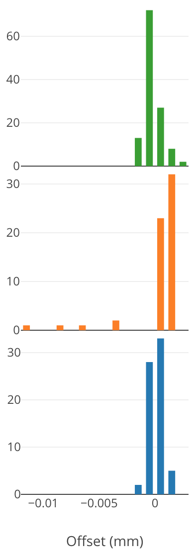
      The approach from that analysis turned out to be remarkably simple and like many other ideas seems to work well in theory, but as we know, the difference between practice and theory is always greater in practice than theory. To get some signal on the practical validity, I prototyped a test on the actual printer, and here are the first results.

      IMG_8284.jpg

      A (somewhat janky) video showing the method running live: https://youtu.be/3ze9RwqkLqU

      The specific parameters for the correction above was f_n=40.4 Hz, zeta=0.

      I got these results without making any FW changes. I instead abused the motion planner by feeding it G-code that simulated the required motion profiles. I think the results look pretty interesting and this is probably worth pursuing further.

      One interesting aspect is that this approach has many similarities to extruder pressure advance. One key difference is that mechanical motion is generally underdamped (zeta<1), while pressure advance is probably overdamped (zeta>1), although I've certainly seen cases where the extruder has a pulsing or oscillating behavior.

      It should be noted though that there are two big limitations to this approach.

      1. This approach does in theory rely on s-curve acceleration profiles (continuous acceleration profiles) in order to give a continuous control signal. It's possible that an approximation will allow it to work reasonably well with classic constant-acceleration profiles (the simulation indicates this), but s-curve acceleration is certainly preferred. Maybe this will end up being the key value proposition for s-curves.
      2. For a similar reason, this approach is incompatible with the "instantaneous velocity change" method that we are used to. I'd like to write a bit more about this later, but the tl;dr is that I think it's time to move away from instantaneous velocity change toward a more general profile smoothing approach. That will have other nice side-effects too.

      Anyway, I thought I'd look for some feedback here before proceeding to explore prototype an actual FW modification.

      posted in General Discussion
      DigitalVisionundefined
      DigitalVision
    • Pressure Advance Calibration

      (My first post here.) I feel printer tuning is still to a large extent a black art that we should be able to turn into a systematic process. As an experiment, I wanted to see if there was an easy way to calibrate the pressure advance coefficient and hacked together a short python script that generates a sequence of fast and slow linear extrusions.

      In this case I did a rather extreme version where print speed changed between 5 mm/s to 100 mm/s, and the pressure advance setting changed from 0 to 0.2s over 10 mm z height.

      0_1535925110977_IMG_1079.JPG

      In this case the optimal setting looks to be 0.074s. (Extruder is direct driven Titan Aero.)

      I've attached the script advance_cal.py and sample test.gcode if anyone else wants to try. The gcode assumed the bed center is (0,0) and likely requires a preamble (heaters, cooling fan etc). I pasted those from another file.

      Is this generally a valid approach, or am I missing something?

      edit: Updated script to support a bed center parameter, proper print height for z0, and python3 compatibility.

      posted in Tuning and tweaking
      DigitalVisionundefined
      DigitalVision
    • RE: A Software Solution to Eliminate Ringing?

      A short update.

      I managed to get some hours to spend on this today, so I rewrote the test code from before mostly from scratch and turned it into a G-code filter. I can now take a regular slicer output file, pass it through the filter and feed the result to the printer. This makes it easier to do realistic testing. The code only really supports linear paths to far, so curves with high tessellation counts will end up looking terrible, but it should work OK for calibration cubes and similar objects. In the process of rewriting it I also implemented some improved machine limits so I won’t have to worry about it trying to move the Z-axis on my cartesian printer at 120 mm/sec.

      Here are some quick-and-dirty results.

      IMG_8327.jpeg
      speed: 80 mm/s, accel: 10 m/s² (10,000 mm/s²), jerk: 2 km/s³ (2,000,000 mm/s³)

      I'm actually pretty happy with that given that this is a 490 g heavy end effector on 375 mm diagonals. For reference, here's what it looks like without any spring-damper compensation:

      IMG_8333.jpeg
      speed: 80 mm/s, accel: 5 m/s² (5,000 mm/s²)

      Pushing it a bit faster.

      IMG_8335.jpg
      speed: 120 mm/s, accel: 20 m/s² (20,000 mm/s²), jerk: 2 km/s³ (2,000,000 mm/s³)
      Some extrusion glitches, but not much ringing.

      I’ll share the code once I’ve written a little documentation on how to use it as I’d love to get some more testing and learnings.

      posted in General Discussion
      DigitalVisionundefined
      DigitalVision
    • RE: A Software Solution to Eliminate Ringing?

      Here's the python test code if anyone wants to give this a shot.

      https://github.com/OskarLinde/dynamic-motion

      The link contains some preliminary instructions for how to use and calibrate the method. You need at least RRF 2.03 since without the M566 P1 jerk policy the G-Code doesn't execute reliably. I was able to run this on an unmodified firmware for simple objects, but found that I could increase the discretization points and run more complex objects if I made a minor firmware change: I disabled the motion planner (look_ahead) if the current move speeds were below the current instantaneous velocity change settings. With this, the extrusion issues in the 120 mm/s print went away. Oh, I also implemented pressure advance correction the script since the firmware one doesn't work with the type of G-Code the script outputs.

      While there are many limitations as described above I'd love to get some testing of this approach: Were you able to get it to work? Were you able to see any improvements in ringing or improvements in print speeds? What type of printer and what calibration values did you land on?

      posted in General Discussion
      DigitalVisionundefined
      DigitalVision
    • RE: [Solved] Curious wood grain pattern on Core XY prints

      The issue is solved now. Thanks everyone for valuable input.

      0_1538894757532_IMG_6457.jpg

      The fact that I got slightly different grain density between 0.6 and 0.4 mm extrusion width made me suspicious. Looking deeper at the grain patterns, comparing them side-by side, I found that they were not perfectly consistent print-to-print. This made me suspect something mechanical.

      The other clue was the fact that the grain patterns changed not with Z, but with layer count. Basically, the shift happened every time the y axis moved. And what could mechanically gradually shift several centimeters over the duration of a print? I could think of only one thing. The recirculating balls in the linear bearings. So I took my y axis apart. The motion of the two bearings felt perfectly smooth when moved by hand, but I still took them apart, took all the balls out – cleaned them with mineral spirits and dried them with ethanol – and among the small pieces of dust and debris that came out of one was what looked like a tiny piece of aluminium shaving. Repackaged them with PTFE grease and issue solved.

      @phaedrux said in Curious wood grain pattern on Core XY prints:

      0.08 seems a little high for a direct drive extruder

      I calibrated it using this technique: https://forum.duet3d.com/topic/6698/pressure-advance-calibration Really quick method to get the value dialed in accurately. (The only other thing I needed to do was to increase the default infill-to-perimeter overlap setting in my slicer, since you can no longer rely on blobbing at the end of long infill lines to fill in the gaps.)

      @rcarlyle said in Curious wood grain pattern on Core XY prints:

      Is it more visible at higher print speeds or lower print speeds?

      Changing print speed made almost no difference at all.

      posted in Tuning and tweaking
      DigitalVisionundefined
      DigitalVision
    • How accurate are mechanical endstops

      I reconfigured my 3 stepper/leadscrew bed to use 3 independent drivers instead of 2 (getting a DueX2 for the one extra driver needed) and added a mechanical endstop on each axis homing the bed like a delta printer. It works well – but one thing I wanted to test was how repeatable the endstops were.

      The firmware doesn't seem to offer a way to test this apart from possibly reconfiguring the endstop under test into a temporary zprobe – so I made a simple simple firmware hack to addH4 option to the G1 command to stop – but not re-home the axis on an endstop hit. I could then log the reported Z pos and repeat multiple times for the three different endstops. Plotting the results as histograms:

      0_1537942747721_58eceae5-b2e2-4982-9001-fd46ad0c5549-image.png

      Some interesting observations. The green and blue endstops seem to be accurate to within ±2 µm (when doing the final homing at 100 mm/min feedrate) which was better than I expected. The orange one had a few outliers –(late triggering) of up to -12 µm – which is probably still not a big deal but higher than necessary. I'll replace this endstop eventually.

      One simple way to improve the homing accuracy that I've used in the past on another firmware is to multi-tap the endstop (e.g. 3,5 or 7 times) and pick the median value. The way RRF is designed though I don't see a straightforward way to implement this. Maybe if there was a g-code command to add the current position to a median accumulator register – and another g-code to move to the accumulated median position plus an offset this could all then be implemented as macros. This functionality could also be used for improved bed probing accuracy.

      Anyway, just thought I'd share this. Having a way to measure endstop accuracy seems like a nice feature to add (something like the H4 option described above), and a way to improve endstop accuracy by filtering out outliers by picking the median position.

      posted in Duet Hardware and wiring
      DigitalVisionundefined
      DigitalVision
    • RE: A Software Solution to Eliminate Ringing?

      Another update.

      Before sharing the python code, I wanted to test it on at least one other printer. This time on a cartesian (CoreXY) printer with CPC linear rails. The printer x-axis is made up of one single 15mm rail with a sole runner block holding the hotend and extruder assembly. The rail itself is very rigid. The weak point is instead the x-axis carrier/runner block that has a bit of yield to its roll axis (resulting in ringing along the y axis).

      In getting the calibration done for this printer I learned a number of new things. First, and very importantly there are actually two modes of ringing. The first one is the one we classicality think of as ringing. It occurs after the printer has decelerates down to a full stop and the end effector oscillates. The photo below illustrates this.

      deceleration.jpg

      The second type of ringing was something I hadn’t considered before. It’s ringing that happens during the acceleration phase. If you look carefully you can see it happening in the simulation in the first figure in https://www.digitalvision.blog/spring-damper-control. The effect may look subtle in that animation, but the result on an actual print is much more substantial. The effect is that the extrusion bead gets stretched and compressed periodically.

      acceleration.jpg

      The effect of this is what I suspect often prevents getting consistent extrusion when printing at high speeds. The extrusion gets ripped apart in the stretching phase. After correcting for this ringing I’ve been able to print consistently even at 150 mm/s with 10 m/s² accelerations, something that I’ve never managed before.

      When observing ringing on a print, you will often see a compound effect of both of these two modes of ringing, with the acceleration ringing from e.g. the x-axis compounding with the post-deceleration ringing from the y-axis. When the two axes have different natural spring frequencies the two axis parameters can be hard to tease apart. For that reason, I came up with the strategy of isolating one axis at a time by setting the acceleration limits of the other axis to a very low value. E.g. 10 m/s² acceleration on the y axis with 0.5 m/s² acceleration on the x.

      My final issue with calibrating this printer was that I was unable to find a single setting that eliminated the ringing on both the left and right side of the print. The left side had a ringing frequency of ~52 Hz with the right side closer to 60 Hz. It seems like the ringing had different frequencies when moving in the positive y direction vs the negative. Thinking a bit about this I came up with a model that makes sense. The print head is not perfectly balanced under the axis with the center of gravity being offset to one side. This effectively means that gravity is applying pre-tension on the spring biasing the spring effect towards one direction. To test this hypothesis I implemented an asymmetric spring model and plugging in 52 and 60 Hz respectively for the two axes did the trick.

      posted in General Discussion
      DigitalVisionundefined
      DigitalVision
    • RE: A Software Solution to Eliminate Ringing?

      @DigitalVision said in A Software Solution to Eliminate Ringing?:

      @sebkritikel said in A Software Solution to Eliminate Ringing?:

      Not quite there yet, but narrowing it down some - the after here is taken at f_n X to 21Hz, f_n Y to 30Hz (X picked after running from 19-26, Y a number of times from 15-50).

      I curious how you end up with such low frequencies and what's dominating the X-spring in your system. Are your belts fairly loose? How long is the X travel?

      A quick theoretical calculation on the timing belt contribution:

      From Gates' datasheet, a GT3 2mm pitch, 6mm wide belt has an elongation of 0.1% @ 16.9 N of force. If we assume that the extruder is 500 g and running at 10,000 mm/s² accelerations we get 5 N of force. That would correspond to an elongation of 0.03 % or 0.3 mm/m. For a belt that is is 1 m, this corresponds to a spring constant of k=17000 N/m. The natural frequency is sqrt(k/m)/(2π) = 29.3 Hz. A 500 mm belt would have a natural frequency of 41.5 Hz.

      I have a CoreXY so there are two belts pulling the extruder. My shorter x belt length from extruder to the motor pulley is ~300 mm at the center and the longer ~1050 mm.

      The long belt will have a spring constant of k=15.9 N/mm and the short one k=55.6 N/mm. Since the two springs work in parallel we can simply add the two spring constants getting k=71.5 N/mm.

      Assuming 500g of extruder weight we get f_n = sqrt(71.5 * 1000 / 0.500) / (2*π) = 60.2 Hz. That's remarkably close to the 60.5 Hz number I got from tuning.

      posted in General Discussion
      DigitalVisionundefined
      DigitalVision
    • RE: Pressure Advance Calibration

      Here's another example on a different printer with a different extruder. Holding the print up to the light clearly shows the inverted color gradients showing differences in extrusion volumes.
      0_1535998086477_IMG_6349.JPG

      @deckingman said in Pressure Advance Calibration:

      @digitalvision Did you really mean extrusion rate between 5 and 100mm/s or did you mean print speed? I suspect the latter as an extrusion rate of 100mm/sec is nowhere near attainable and would relate to a print speed in the order of 5,000 mm/sec.

      Yes, I meant print speed – thanks for pointing that out. The theory being that with proper pressure advance the extrusion width should remain constant independent of print speed and acceleration/deceleration.

      @wilriker said in Pressure Advance Calibration:

      @digitalvision Might be relevant to other trying to test: this is python2 syntax and won't run with python3.

      Thanks – updated the script to be python 2/3 compatible. Apologies for the messy script too – this was literally a 15 minute hack.

      @obeliks said in Pressure Advance Calibration:

      So if I want to have gcode for printer with 0,0 on the corner I need to change to this?
      curr_x = 110
      curr_y = 110

      I updated the script to allow a bed center setting.

      posted in Tuning and tweaking
      DigitalVisionundefined
      DigitalVision
    • RE: A Software Solution to Eliminate Ringing?

      Update...

      I was a bit concerned about the idea that wave propagation delay in the belts would be significant enough to affect the spring-damper model as my earlier calculation indicated. I'm happy to conclude that I was wrong. I had calculated the transversal wave propagation velocity when what actually matters is the longitudinal wave propagation velocity (or speed of sound) which is substantially higher. For my GT3 belt, the speed of sound is around 1.5 km/s which means that the force propagation delay over my longest belt segment is <1 ms. We need to make signal changes at close to kHz speeds for this to become relevant. I made a small simulation to convince myself of this, and as long as the belt tension is substantially higher than the maximum acceleration force the belt will behave as a perfect spring. Here’s a great source on theory of longitudinal wave propagation: https://www.mathpages.com/home/kmath569/kmath569.htm

      The complication is that the spring "constant' is dependent on the spring length which changes with the position. Luckily we can measure and calculate this correction almost perfectly. Here’s a plot of how the ringing frequency theoretically changes across the print bed for a cartesian and CoreXY printer respectively. We can see how the two-belt CoreXY design balances the effect much better than a single linear-belt (with the stepper on one side) does. The linear belt design has a substantially higher spring stiffness when the print head is close to the stepper than when it’s far away and I think it’s clear that we need a positional parameter even for the CoreXY system.

      946d5504-260c-40b8-a967-2a91bedd2f34-image.png

      Both of these functions are of the form sqrt(1/p) where p is a quadratic polynomial. For the cartesian case p(x) has 3 parameters of which one is the relative belt lengths for a given x-coordinate and can be easily measured. If we add other serial springs to the system (like the stepper motors and compliant mechanics) we get another simple additive term. Measuring f_n at two different positions will determine the entire system.

      513f459c-cce0-48d3-b70a-5740edf3e4db-image.png

      For a CoreXY system it gets a bit more complicated since the belt lengths depend on both x and y. The compounded spring model is also a bit more complicated:

      5652fc79-9861-4152-8d6a-c9720d17a636-image.png

      For one axis, we have 5 unknown parameters: stiffness of the x and y belt respectively, the serial spring at the end effector and the two stepper springs. We can probably assume that the two steppers are identical and collapse them to one parameter, but we are still left with 4 parameters. For the other axis, many of these parameters overlap. The steppers and belts are identical with only a difference in the driven mass. The serial spring is also different. So we have a total of 6 parameters across two axes. This means that we need to measure f_n for three points per axis rather than two to determine the parameters for the system.

      One more thing. Can we calculate the spring constant from a stepper motor? The electrical field in the motor is effectively a spring, and at a static position the spring constant may at a first order be able to be calculated as the holding torque over one full step. I.e. once you exceed the holding torque the stepper will be closer to the next step 2 steps away than the current one and skip.

      My stepper's data sheet claim a holding torque of 0.43 Nm and are rated at 1.684 A. I run them at 85% max current though, so 0.37 Nm. They have a 0.9° step size, 18 tooth pulleys with 2mm pitch belt, so the radius is 5.7 mm. If I calculate correctly, this gives me a spring constant of 710,000 N/m or around 10x higher stiffness than the belts. The impact is still a reduction of f_n of around ~4 Hz though, so not insignificant. I wonder if this linear spring force calculation is valid (especially for micro stepping too) though. There is definitely a reduction in torque at speed too. How significant is that at the speeds we run at?

      posted in General Discussion
      DigitalVisionundefined
      DigitalVision
    • RE: Pressure Advance Calibration

      @obeliks said in Pressure Advance Calibration:

      @digitalvision Thanks.
      Now can someone explain my stupid ass how to output the result to a file? 😊

      Try:

      python advance_cal.py > advance_cal.gcode
      
      posted in Tuning and tweaking
      DigitalVisionundefined
      DigitalVision
    • RE: Help with strange diagonal banding on Ultibots D300VS+ ?!

      I encountered a similar issue the other day on my CoreXY printer. Here's a PLA spiral mode print of a ø20mm cylinder, 0.1 mm layer height, 0.4 mm extrusion width limited by the slicer to 5 s per layer which translates into ~12.5 mm/sec nozzle speed or 0.5 mm^3/s.

      0_1538622734127_IMG_6442.jpg

      I first suspected z stage issues (the vertical period is ~.5 mm (5 layers) which is a quarter the z stage pitch), but wanted to test if it could be extruder related when I noted that the diagonal patterns spiralled around the print. The horizontal period for the pattern is ~6.3 mm – and this doesn't correspond to a the step size (~96 steps/mm @ 16 microstepping) and is also far too small to correspond to the hobbed gear tooth spacing. Still, I tried another print with a wider extrusion width of 0.6 mm to see the effect on the pattern and somewhat surprisingly the phenomenon disappeared completely:

      0_1538622742338_IMG_6441.jpg

      Repeating this with higher print speed also eliminated the issue. So my suspicion is that when printing with too low of a flow rate the nozzle back pressure is insufficient to preserve a laminar flow and the result seems to be a periodic pulsing pattern.

      I haven't seen this phenomenon with other filament, and this particular one has the most amount of die swell I've ever seen – free air extrusion from a 0.4 mm nozzle swells to 1.7 mm.

      posted in Tuning and tweaking
      DigitalVisionundefined
      DigitalVision
    • RE: A Software Solution to Eliminate Ringing?

      @Adamfilip said in A Software Solution to Eliminate Ringing?:

      Awesome, looking forward to hearing @dc42 thoughts on this.

      Me too. Funny – I just went back to a >2 year old post of mine here and found this comment by @dc42:

      My thinking is this. Let's assume a Cartesian printer for now. In order to accelerate (say) the X axis, the motor and belt have to impart a force to the head given by F=ma. But the belt and the motor are springy, so in order to really impart force F to the mass of the print carriage, the motor must move by an additional amount S=ma/k where k is the spring constant. If the acceleration changes abruptly, then this requires instantaneous changes in motor position, which are impossible; but if we use S-curve acceleration then the required changes in motor position are gradual and should be achievable.

      I never really registered that back then (I was focused on figuring out why my extruder wasn't behaving according to theory), but this must have planted a seed in my subconsciousness.

      So, with this serving as a kind of proof of concept I'd love to hear dc42's thoughts on this:

      1. Replacing "instantaneous velocity change" with a simple smoothing pre-processor that replaces sharp corners with small arc segments (G2/G3) controlled by a smoothness parameter (e.g. G187). There are plenty of options here with e.g. an angle criterium to heuristically identify curve approximations vs sharp corners, but a simple 'max deviation' should probably suffice initially. Ideally you want to implement a transition curve rather than a simple arc to keep the acceleration continuous, but continuous velocity with an approximate correction may be sufficient initially. The arc approach could be prototyped as a simple offline pre-processor at first.
      2. Approximating the spring-damper-correction without s-curves as the simulation seems to indicate could work.
      3. The effort/plan to implement true s-curve motion control. This seems like the inevitable end-state.
      posted in General Discussion
      DigitalVisionundefined
      DigitalVision
    • RE: Help with strange diagonal banding on Ultibots D300VS+ ?!

      @wwmotorsports

      Here's a suggestion for a quick experiment that might help narrow down the cause.

      • Print a single walled cylinder diameter 100 mm without infill. Spiralized/vase mode should work. No bottom layer needed. Make sure the print is centered on the print bed. Observe the print to see if the pattern appears.

      • If it doesn't appear clearly change the object to an equilateral triangle.

      • If the pattern it doesn't appear, add a second perimeter and infill.

      • If the pattern is asymmetric it is probably related to one of the three towers / arms. The direction of asymmetry could tell you which.

      • If the pattern is symmetric around the bed center, increase the extrusion factor to 150% (can be done during printing – for a single walled print this is equivalent to increasing the extrusion width by 50 %).

      • If the pattern changes in frequency or pitch angle – it stems from the extruder.

      • If it doesn't change, it's likely motion related.

      posted in Tuning and tweaking
      DigitalVisionundefined
      DigitalVision
    • RE: A Software Solution to Eliminate Ringing?

      @LB said in A Software Solution to Eliminate Ringing?:

      @DigitalVision
      Wow - would be great to have this optional sometime in the future! Would be great to have beside the option to calculate the val the "old" try-n-error option to print a tower with diffrent "zeta"-val...

      Thanks. Calibrating the f_n is actually really easy using a similar approach to my proposed method of calibrating pressure advance. You print a simple test print varying the f_n parameter layer-by-layer. You will see a very clear phase inversion in the ringing pattern at the point that corresponds to the right f_n number and you can simply measure the height of that inversion to find the right value. That's how I determined the f_n = 40.4 Hz value above. A less accurate / coarse method is to measure the ringing spacing (peak-to-peak) at known print speed. In this case, 80 mm/s print speed, 40 Hz natural frequency corresponds to 2mm peak-to-peak spacing.

      Just exploring all this for me new stuff, I stumbled across "Helling-Bestehorn" (the "smooth-runner") and "Polynom of the 5th order" which seems to be an "allrounder" in terms of motion-control - would really like to hear your opinion on it...

      I've not heard about Helling-Bestehorn – seems like a sinusoidal interpolation basis function. For smooth interpolants that satisfy a continuous curvature constraint (e.g. continuous centrifugal force) a 5th order polynomial is the most straightforward choice. You have 6 coefficients that you solve by 6 constraints: at each end you fix the position, velocity and curvature and you get a simple closed form solution for the polynomial coefficients. I've looked at this to smooth tessellated paths into a continuous curve.

      posted in General Discussion
      DigitalVisionundefined
      DigitalVision
    • RE: Pressure Advance Calibration

      To see if I could separate extrusion from motion effects, as an experiment, I built a small jig to measure the thickness of a single-walled print. I then printed a 150 mm long print with uniform print speed (50 mm/s), but varying extrusion volume (0.7 -> 0.4 -> 0.7 mm extrusion width) as a step function. One caliper of the jig measures thickness (mechanically magnified 4x) and another the x position along the test print. Manually measuring a number of positions gave the following result. I'm treating wall thickness * layer height * linear distance as an approximation for extrusion volume here (ignoring the fine layer induced surface structure).

      0_1539501856465_2e598be3-ecd5-4bfa-a31e-732718f07c51-image.png

      For a first quick experiment, I'm pretty happy with how nice the data looks. Interfacing digitally with the calipers would make this a lot quicker though.

      I'm not sure why the first segment didn't converge to the same value as the last one – but I can see some minor ripples that look like the print needs a bit more cooling towards the end of the first segment that may pollute the measurements a bit. I'll retry with some delay between each layer to allow for more cooling next time.

      @dc42, when running at constant linear speed but varying extrusion rate like this pressure advance doesn't seem to have any effect. Is that expected?

      I'll redo this for a few different extrusion rate pairs and see how well I can get the current model to fit.

      posted in Tuning and tweaking
      DigitalVisionundefined
      DigitalVision
    • RE: A Software Solution to Eliminate Ringing?

      If this method will turn out to be useful, here’s what I think the likely end-state (at least as far as I can see) is for 3D printer motion control.

      To replace instantaneous velocity change to handle segmented curves in a continuous motion, it is likely that we need a way of defining smooth (G2 continuous) profiles. Using some type of spline representation is probably the best choice, and out of the different representations NURBS is the most obvious one, since it has a number of good properties like the ability represent conics (like circular arcs) exactly. We can certainly get away with something slightly simpler than NURBS, but the difference in complexity is hardly significant.

      Afaik, there is no good spline representation that has a straightforward arc-length parametrization though, something we need to effectively generate physical motion profiles (and achieve C2 continuity). The best path is probably to create a re-parametrization through a second approximating spline (approximating the inverse of the arc-length function).

      With this we can generalize the current motion primitives (line segments, arcs), support transition curves and other smoothing primitives including the ability to represent (and possibly reconstruct) the original curved surfaces that were used to generate tessellated polygonal/STL representations.

      With S-curve motion, acceleration planning would be the job of defining (at a minimum) a piecewise linear acceleration profile over the arc-length parameter ensuring adherence to all motion limits. Higher orders than 3 may be valuable to model more complex compounded spring-damper systems, but lacking any proof of that a 3rd order model seems right.

      So we get effectively 4 functions:

      1. From the motion planner, we get a (at minimum piecewise-linear and continuous) function a(t), that when doubly integrated gives a mapping s(t) from time t to arc length s.
      2. From the inverse arc-length-approximating spline, we get another mapping q(s) from s to the NURBS parameter q.
      3. From the NURBS profile we get the mapping from q to the spatial dimensions {x,y,z,e,…}
      4. From the spatial dimensions we apply model-based control (spring-damper correction) and machine configuration to get final actuator axes positions.

      A somewhat complicating factor is that I believe today there is a tight coupling from 4 back to 1. Motion constraints defined in actuator space feed back to the motion planner. With today’s simple motion primitives these constraints can probably be expressed in closed form with respect to the acceleration profile, but I don’t think that’s going to be easy or even possible with the above scheme. One option (a) is to decouple this by providing (or calculating) sufficient guard-rails to the spatial constraints for the motion planner that machine constraints don’t need to be considered. Another option (b) is an iterative process feeding back e.g. Taylor-approximations of the constraint mappings.

      The nice thing about option a is that it simplifies the implementation significantly, and with some limitations even allows 1-3 to be computed offline. That’s effectively what I did above but with a much simpler geometric profile. I also included the model parameters for the spring compensation though, which unfortunately makes the output incompatible with the model-based control RRF already does for extruder pressure advance, so I had to disable that.

      For prototyping I can fairly easily hack 1-3 together, creating a time-parametrized motion profile. I wonder how to best feed that to RRF is though. Since RRF supports constant acceleration segments already, they’d be great candidates to approximate the profile. I.e. pairs of M204 (acceleration limit) and G1 commands to describe the path. For this to work with high segment rates, I’d probably need to hack the firmware a little bit to bypass the motion planner and instead have it follow the provided motion profile exactly, although I’d love to hear if there are better options.

      posted in General Discussion
      DigitalVisionundefined
      DigitalVision
    • RE: A Software Solution to Eliminate Ringing?

      @sebkritikel said in A Software Solution to Eliminate Ringing?:

      Despite the fact my machine is half disassembled, and the fact I recently swapped out extruder motors without much 'calibration' this has been pretty cool to work with. I don't think I have anything workable yet, but still neat to play with. Once I get my machine put back together, hopefully I'll be able able to work through the parameters more methodically.

      Thanks for testing! These are very interesting results.

      A quick note - I'm thinking the z_max (in mm) parameter is a bit wonky, initially I did some thin wall prints that were 100mm tall, and could only see variation (both in Craftware for previewing) and in the print for the first 20mm or so - even if I set z_max to 100. When I set it to 20mm (for a 20mm tall print) it also looks like the variation occurs in the first 5-8mm or so.

      I don't think the parameter is broken – it's more the consequence to the correction magnitude of increasing f_n. The higher the number the smaller the correction, asymptotically approaching zero. The correction magnitude is proportional one over the square of the f_n number, so at say 50 Hz you will get 4x less correction than at 25 Hz, and at 5 Hz (your lowest number, the correction is 100x higher.

      I modified the python files to eliminate changes to the Z axis (had some issues during my first few tests).
      I get some significant defects due to the bed oscillating on layer changes. Some potentially useful information from the config.g

      Looking at your g-code, your slicer is not spiralizing the contour, so I think your modifications are ok. You should be able to achieve the same effect by reducing the accel setting in the z axis limits though.

      The unmodified print file: JP_talltestPart2.gcode

      Short video of unmodified print - https://www.youtube.com/watch?v=3PDYEEwW7_I

      First I ran a print of the above file - shown as "F" in pictures below ("F" for front of build plate haha). Printed with HIPS at somewhat high temperatures, no part cooling, 100mm/s. In the FRONT view, the printhead moves left to right along the X axis. In the Right view, the nozzle moves left to right along the Y axis... etc. DAA, PA, etc, all were turned off for the reference print. The reference print is stacked on top of the modified gcode print. For "Fx" I ran the script targeting x f_n, ranging from 5 to 75 across Z=20 (see note above). Yes, the X axis did a good amount of shaking.

      Video - https://www.youtube.com/watch?v=6TJ2uW1rX_E
      File - x-5-75.gcode

      alt text

      On the front view, you definitely see a significant improvement around one third up corresponding to roughly 25~30 Hz. I don't quite understand what's happening on the back side though. I think maybe the lack of cooling keeps the filament from achieving good adherence to the layer below.

          axis_limits = [
              move.axis_limits(speed = 300), # x
              move.axis_limits(speed = 300, accel=500), # y
              move.axis_limits(speed = 22, accel = 1200, jerk = 1000), # z
      

      With such a low jerk value, I'm surprised you have issues with the z axis.

      For the image below, same notes - targeted Y axis. I read your warning on going below 20Hz and promptly ignored it hahahahaha

      Video - https://www.youtube.com/watch?v=Yc9EpRiLeGE
      y-5-75.gcode
      alt text

      You should definitely increase the low end of the range from 5Hz to something higher (15 Hz maybe?). The poor extrusion at the bottom is making reading these quite hard. Another thing that helps is plugging in the ~28 Hz value from the X-axis calibration above here to minimize the cross-talk. That being said, you can definitely see a phase transitioning happening in the range of 25-50 % of the height. I've generally been successful picking the middle point of the phase transition.

      Fun to watch and futz with (I did many more prints prior to this), but unfortunately nothing conclusive. What I did do was measure the ringing in the reference print on each side, and then ran the print again only targeting those values (no value hunting). I threw in X=25Hz, and (the reason escapes me now) Y=30Hz. The amplitude of the vibrations are much lower (read: surface is smoother) than the reference print (I also ran a print swapping the X and Y values, where in the inverted prints the results were not as good). Unfortunately the picture doesn't quite paint a clear picture.
      17fb88dc-8f1d-414a-91ad-98b4446757bf-image.png

      alt text

      I think this is a good start. It always took me a few iterations to get it tuned, you should zoom in on the parameters a bit more (e.g try 20–35 Hz). Zeta can also be critical to calibrate (depending on your printer). It's also possible that doing 12000 mm/s² acceleration is aiming too high and you start hitting non-linear spring behaviors. My CoreXY printer has ringing in the range of 52-60 Hz which is almost exactly 2x of your values. Since that means 4x as much spring compensation I'd not be surprised if you need to back off on the acceleration setting.

      The thing about photos of shiny filament is that they amplify the curvature changes over the magnitude – you see similar specularities even after reducing the ringing magnitude by a significant factor. You probably want to get your f_n estimates to within 2–5% or so to start seeing more dramatic improvements.

      Finding my most similar silver filament, here an "after" print I made on my CoreXY:

      IMG_8363.jpg
      80 mm/s, 10,000 mm/s², 2 km/s³ jerk

      I didn't have enough filament to finish a "before" shot. This was as far as I got:

      IMG_8364.jpg
      (identical printing parameters)

      Ignore the horizontal lines in the middle of the silver zone – that's when I fed in the gold filament.

      posted in General Discussion
      DigitalVisionundefined
      DigitalVision
    • RE: A Software Solution to Eliminate Ringing?

      Just a closing thought on the above. Not entirely surprising it seems the belts have the potential to explain almost all of the spring dynamics on my printer. The belt lengths are a critical parameter though, and they will vary significantly across the print envelope, so a single f_n parameter will probably not work across all of it. Luckily it's very easy to calculate the belt lengths at any given point, so it should be easy to build a simple dynamic model to correct for this.

      posted in General Discussion
      DigitalVisionundefined
      DigitalVision
    • RE: A Software Solution to Eliminate Ringing?

      @DigitalVision said in A Software Solution to Eliminate Ringing?:

      Assuming 500g of extruder weight we get f_n = sqrt(71.5 * 1000 / 0.500) / (2*π) = 60.2 Hz. That's remarkably close to the 60.5 Hz number I got from tuning.

      One thing that's been bugging me about this calculation is that I'm leaving out the counter-spring from the opposing belt. I initially thought that spring force wouldn't matter since that side would be slacking. But would it really?

      If we model the belt like a spring like this:

      eb6af79a-0a8b-4bd0-8e5d-dc2552dc6176-image.png

      And then add a counter spring and apply some tension to the belt we get the following two forces:

      85bb9219-f458-4bc0-a5c1-9b800029497f-image.png

      Summing these two, we should expect a net spring function like this:

      abc99d07-ed44-4064-84c3-95ea45d67cfa-image.png

      Note that the slope in the center region is twice that from my calculation above, and only beyond the cutoff point (when it exceeds the pre-tension) will the opposing end of the belt slack. So we should in theory expect a sqrt(2) ≈ 1.41 higher ringing frequency than I calculated. I.e. 85 Hz vs 60 Hz. Since I’m not getting that something is off. I can come up with three hypotheses:

      1. The acceleration exceeds the belt tension causing the opposing belt to slack. This would mean that we operate in the 1 * k slope regime (as opposed to 2 * k).
      2. The momentary spring displacement is faster than the wave propagation to the opposing side. I.e. when the end-effector jerks to one side the opposing belt end hasn’t yet realized it and had a chance to relax.
      3. There is another other (serial) spring in the system reducing the ringing frequency.

      So let’s test these:

      1. We can model our belt as a vibrating string. Plucking my belt between two idlers 417 mm apart gives a 65 Hz tone. The base frequency for a string is f₁ = sqrt(T/(m/L))/(2*L), T=tension (N), L = length, m = mass. The best value I found for the mass of a 2mm pitch 6mm wide GT3 belt is 7.8 g/m. Plugging these numbers in gives a tension of 26 N. Since this is substantially higher than the 5 N of acceleration force we can reject this hypothesis.

      2. The wave propagation speed through a string is sqrt(T/(m/L)), or f₁ * 2L. 65 Hz * 2 * 0.417m = 54.2 m/s. My belt is ~1.4 m end-to-end, so it takes 26 ms for a wave to propagate through it. Since this is substantially longer than even the half-period of ringing (1/60 Hz) / 2 = 8.3 ms I think we have our answer. The opposing belt will not have had time to relax its counter force for more than a full period of the ringing leading to the lower slope characteristic of the spring function.

      posted in General Discussion
      DigitalVisionundefined
      DigitalVision