Hello everyone,
TL;DR: Motors started to vibrate weirdly after stall during lowering the bed. 3 motors were connected in parallel to one driver, and I've forgot to increase current in config for 3 motors instead of 1.
Full story:
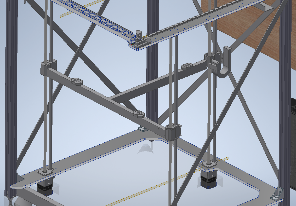
I was assembling lead screws and linear rods (triple Z axis, 700mm travel) for my printer. I hope you can see it well enough on picture below:
At first I've tested only 1 Z axis with 1 motor connected to driver. I've settled on F3000 (50mm/s) and 2A peak current (1,42A RMS). So it is fast enough to travel those 700mm and not so loud - except typical high pith noise of low quality motors . Motors are "Minebea", Model: 17PM-K940-P6VS, 1,8°, 1,5A, 0,45Nm and measured phase resistance of around 1,65Ω, unfortunately I couldn't find any documentation of this motor so inductance is unknown.
Since everything looked fine I've assembled all 3 Z axis and T frame with kinematic coupling for the head bed (as seen on picture). Next all 3 motors were connected in parallel to one driver. Did few more up-down travels of this assembly to check it out. All being fine I thought "ok, now lets throw my 516x516x10 aluminium on it and see hot it fits"
And as you can guess, on first down move (I think order was 100mm) I've heard loud noise of stalled motors. I didn't have my E stop in hand so it lasted for 2 seconds. In reality all motors stalled in a sequence, cause bed was heavily tilted to one side (around 50mm). To correct my mistake, I've cut power, moved bed to kind of levelled state, restarter board and set higher current for Z to be 5A peak (3,54A RMS).
To my surprise motors were now loud as hell, whole printer was shaking. So I took bed of from T frame, but it didn't change anything. I did some test and it looks like something permanently changed.
When I power only 1 motor (F3000 (50mm/s) and 2A peak current) it works fine (at least as I can remember how it was before crash). But when 2 motors are connected in parallel, with 2x current, both of them are very loud and shaking. I lowered speed to F1000. This decreased noise a lot but when I was holding motor in hand I could feel irregular "grinding or crunching like" vibrations. But when the same motor is connected alone I don't feel this "grinding". I've teardown this motor but didn't found anything out of order, bearings were fine etc.
My quick conclusion was that driver was damaged. So I've redo tests on different driver but no change was observed.
Next I've checked setting in config to see any changes, but all drivers are working in default spread cycle.
I know that those motors aren't highest quality, and are for test purposes only (I am planning on getting my hands on something name brand later). But apart from that, what happened (very loud motors after crash) is a mystery for me and shouldn't happen. I would like to find the cause of this instead of "just get better motors".
I run latest firmware and DWC, my config below:
; Configuration file for Duet 3 (firmware version 3)
; executed by the firmware on start-up
;
; generated by RepRapFirmware Configuration Tool v3.1.10 on Fri Dec 11 2020 19:50:46 GMT+0100 (Central European Standard Time)

; General preferences
G90                                          ; send absolute coordinates...
M83                                          ; ...but relative extruder moves
M550 P"Arato"                                ; set printer name
M669 K1                                      ; select CoreXY mode

M955 P0 I25 S1600 R16 C"spi.cs3+spi.cs2" ; all wires connected to temp DB connector - Accelerometer creation

; Network
M552 P0.0.0.0 S1                             ; enable network and acquire dynamic address via DHCP
M586 P0 S1                                   ; enable HTTP
M586 P1 S0                                   ; disable FTP
M586 P2 S0                                   ; disable Telnet

; Drives
M569 P0.0 S1                                 ; physical drive 0.0 goes forwards lewy motor
M569 P0.1 S1                                 ; physical drive 0.1 goes forwards prawy motor
M569 P0.2 S0                                 ; physical drive 0.2 goes backwards Z motors tymczasowo
M569 P0.3 S0                                 ; physical drive 0.3 goes backwards Extruder?
M569 P0.5 S1								; T locking pin

; test drivera Z
;M569 P0.5 S0                                 ; physical drive 0.2 goes backwards

M584 X0.0 Y0.1 Z0.2 E0.3 ;C0.5						; set drive mapping

; test drivera Z
;M584 X0.0 Y0.1 Z0.5 ;E0.3 ;C0.5						; set drive mapping

M350 X16 Y16 Z16 E16 I1								; configure microstepping with interpolation
M350 C16 I1
M92 X100.00 Y100.00 Z1600.00 E1376 C100				; set steps per mm
M566 X2000.00 Y2000.00 Z60.00 E120.00 C20			; set maximum instantaneous speed changes (mm/min)

;M203 X60000.00 Y60000.00 Z200.00 E2400.00 C6000  	; set maximum speeds (mm/min)
M203 X30000.00 Y30000.00 Z1000.00 E3000.00 C600	  	; set maximum speeds (mm/min)


;M201 X40000.00 Y40000.00 Z40.00 E10000.00 C1000    	; set accelerations (mm/s^2)
M201 X4000.00 Y4000.00 Z120.00 E10000.00 C500    	; set accelerations (mm/s^2)

;M204 P30000 T50000									; set accelerations (mm/s^2) P- printing T- travel
M204 P3000 T5000									; set accelerations (mm/s^2) P- printing T- travel

M906 X4000 Y4000 Z2000 E850 C600 I30              	; set motor currents (Peak mA) and motor idle factor in per cent
M84 S1												; Set idle timeout

; Axis Limits
;M208 X0 Y0 Z0 S1                             ; set axis minima
;M208 X568 Y565 Z500 S0                       ; set axis maxima

; Print area (0,0) - (500,500)
M208 S1 X-34 Y-4 Z0    ; set axis lower limits
M208 S0 X534 Y562 Z500 ; set axis upper limits


; Endstops
M574 X1 S1 P"io0.in"                         ; configure active-high endstop for low end on X via pin io0.in
M574 Y1 S1 P"io1.in"                         ; configure active-high endstop for low end on Y via pin io1.in
M574 Z1 S2                                   ; configure Z-probe endstop for low end on Z
; M574 C1 S3

; Z-Probe
M558 P5 C"^io2.in" H5 F600 T30000			; set Z probe type to switch and the dive height + speeds
G31 P500 X0 Y0 Z2.5							; set Z probe trigger value, offset and trigger height
M557 X0:500 Y0:500 S250						; define mesh grid

;Stall Detection
; M915 C S6 F0 H200 R0					; Coupler

; Heaters
M308 S0 P"temp0" Y"thermistor" T100000 B4138 ; configure sensor 0 as thermistor on pin temp0
M950 H0 C"out0" T0                           ; create bed heater output on out0 and map it to sensor 0
M307 H0 B1 S1.00                             ; enable bang-bang mode for the bed heater and set PWM limit
M140 H0                                      ; map heated bed to heater 0
M143 H0 S120                                 ; set temperature limit for heater 0 to 120C
M308 S1 P"temp1" Y"thermistor" T100000 B4138 ; configure sensor 1 as thermistor on pin temp1
M950 H1 C"out1" T1                           ; create nozzle heater output on out1 and map it to sensor 1
M307 H1 B0 S1.00                             ; disable bang-bang mode for heater  and set PWM limit
M143 H1 S280                                 ; set temperature limit for heater 1 to 280C

; Fans
M950 F0 C"out4" Q500                         ; create fan 0 on pin out4 and set its frequency
M106 P0 S0 H-1                               ; set fan 0 value. Thermostatic control is turned off
M950 F1 C"out5" Q500                         ; create fan 1 on pin out5 and set its frequency
M106 P1 S1 H-1                               ; set fan 1 value. Thermostatic control is turned off

; Tools
M563 P0 D0 H1 F0                             ; define tool 0
G10 P0 X0 Y0 Z0                              ; set tool 0 axis offsets
G10 P0 R0 S0                                 ; set initial tool 0 active and standby temperatures to 0C

; Custom settings are not defined

M950 J1 C"io8.in"			; E STOP - stopping movements
M581 P1 T0 S1 R0			;


