Duet3D Logo Duet3D
    • Tags
    • Documentation
    • Order
    • Register
    • Login

    Duet Wifi Closed Loop and Panel Due

    Scheduled Pinned Locked Moved
    Accessories and Add-ons
    breakout board closed loop help panel due setup wiring
    5
    23
    1.7k
    Loading More Posts
    • Oldest to Newest
    • Newest to Oldest
    • Most Votes
    Reply
    • Reply as topic
    Log in to reply
    This topic has been deleted. Only users with topic management privileges can see it.
    • Gost101undefined
      Gost101
      last edited by Gost101

      Good Day everyone,

      I am once again asking for your help.

      I bought 5 of these closed loop drivers for the breakout board and do not want to screw up the wiring. Hd987706388d44bf4bc9b43029b27291a5.jpg_640x640q90.jpg
      Capture.PNG
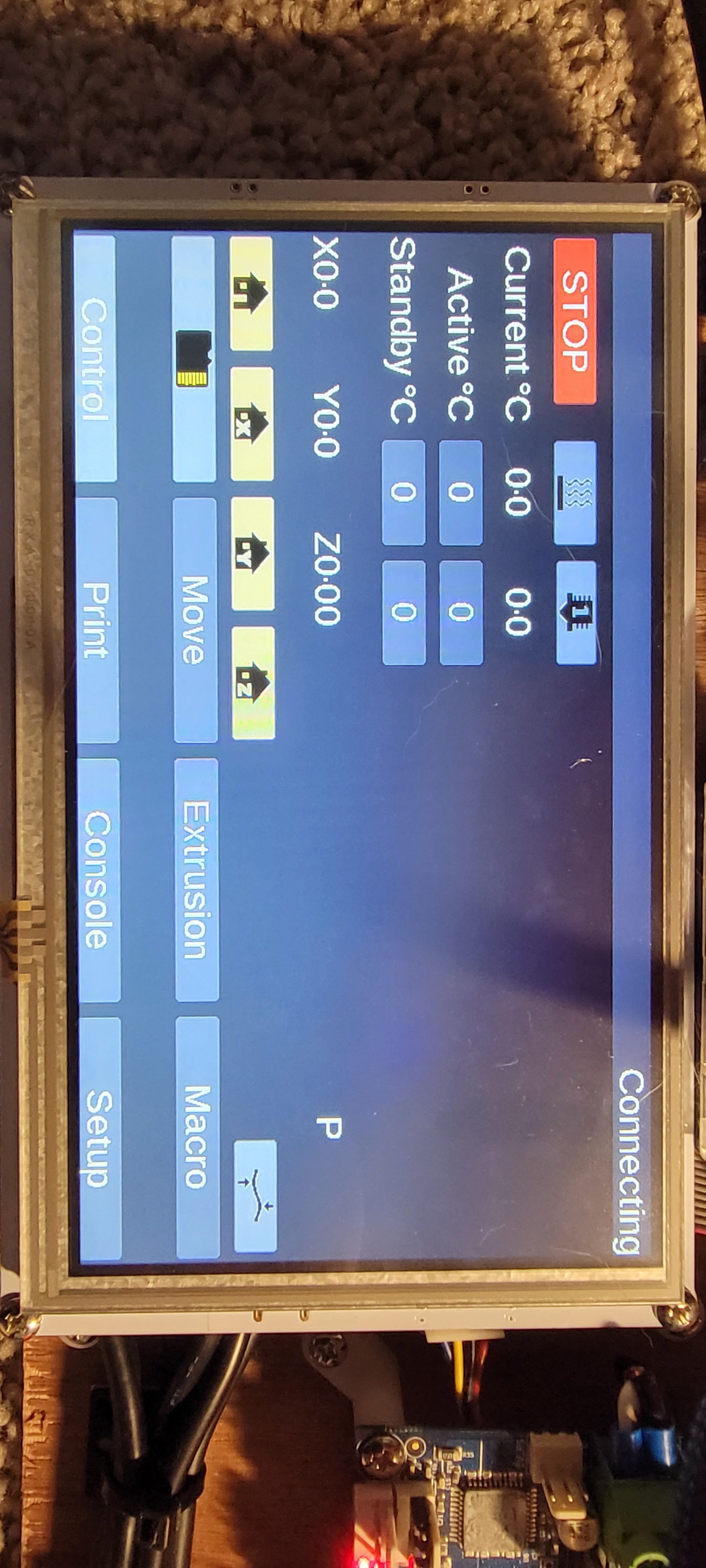
      In addition, I have a 7" panel due that is connected over the ribbon cable as the guide suggests and I have added the ```
      M575 P1 S1 B57600

      
      ![20210813_180512.jpg](/assets/uploads/files/1628902118736-20210813_180512.jpg) 
      
      Here is a print out from the YAT terminal: FIRMWARE_NAME: RepRapFirmware for Duet 2 WiFi/Ethernet FIRMWARE_VERSION: 3.3beta1 ELECTRONICS: Duet WiFi 1.02 or later FIRMWARE_DATE: 2021-02-14 16:00:49<LF>ok<LF>
      
      What should I do?
      1 Reply Last reply Reply Quote 0
      • Gost101undefined
        Gost101
        last edited by

        20210813_180512.jpg

        1 Reply Last reply Reply Quote 0
        • Phaedruxundefined
          Phaedrux Moderator
          last edited by Phaedrux

          Update your firmware to 3.3 final for the duet and the panel.

          Make sure the panel baud rate in the setup page matches the value in config.g

          Have you tried the 4 wire connection method yet?

          Z-Bot CoreXY Build | Thingiverse Profile

          Gost101undefined 1 Reply Last reply Reply Quote 0
          • Gost101undefined
            Gost101 @Phaedrux
            last edited by

            @phaedrux The Panel Due now works. Thanks. But how should I wire the stepper motor drivers from the breakout board?

            1 Reply Last reply Reply Quote 0
            • Phaedruxundefined
              Phaedrux Moderator
              last edited by

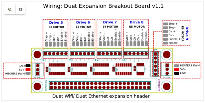
              Have you seen this page?
              https://duet3d.dozuki.com/Wiki/Duet_Expansion_Breakout_Board

              Do you have any information on how that board uses the step/direction/enable pins? I'm not familiar with that board myself.

              Z-Bot CoreXY Build | Thingiverse Profile

              1 Reply Last reply Reply Quote 0
              • Gost101undefined
                Gost101
                last edited by

                @phaedrux I have seen that post and no I am not familiar with the wiring of the closed loop driver that's why I asked LOL. Do you know anyone who might be?

                1 Reply Last reply Reply Quote 0
                • Phaedruxundefined
                  Phaedrux Moderator
                  last edited by

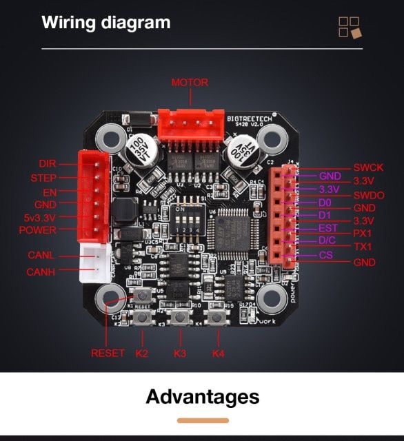
                  Do you have a link for the big tree tech board?

                  Z-Bot CoreXY Build | Thingiverse Profile

                  JoergS5undefined 1 Reply Last reply Reply Quote 0
                  • JoergS5undefined
                    JoergS5 @Phaedrux
                    last edited by JoergS5

                    @phaedrux @Phaedrux here is a bit of information about the S42B v2.0: https://github.com/bigtreetech/BIGTREETECH-Stepper-Motor-Driver/tree/master/S42B/V2.0
                    On page 11-12 of the first document is some information about dir/step/enable.

                    The link was from https://www.reddit.com/r/BIGTREETECH/comments/l0xtgs/btt_s42b_v20_not_working_properly_what_am_i/, mentioning, that the dip switch documentation may be wrong.

                    alankilianundefined 1 Reply Last reply Reply Quote 0
                    • alankilianundefined
                      alankilian @JoergS5
                      last edited by

                      I don't know enough to be able to help with the original poster's questions, but I have one of my own.

                      What do people think they are going to achieve using a closed-loop control board between their path creation machine (Duet) and their stepper motor?

                      My experience measuring command-vs-actual positions showed that the stepper motor positions dramatically lagged the commanded position, and the position bounced all around at the beginning and end of moves. It would have produce terrible 3D prints.

                      Do people think this is going to produce a more accurate position-control for their systems, because it's likely to not do that.

                      This system is VERY different from the one being planned where the path-generating software and the closed-loop software are both running on the same machine like the new Duet closed-loop system being tested now.

                      It would be interesting to see if anyone has gotten an external closed-loop system like this to NOT produce worse results then a properly-loaded open-loop system.

                      SeemeCNC Rostock Max V3 converted to V3.2 with a Duet2 Ethernet Firmware 3.2 and SE300

                      Gost101undefined 1 Reply Last reply Reply Quote 1
                      • Gost101undefined
                        Gost101 @alankilian
                        last edited by

                        @alankilian @JoergS5 Does this mean you guys can help me? I have no idea as per which connector on the breadboard connects to which connector on the closed loop board.

                        1 Reply Last reply Reply Quote 0
                        • Phaedruxundefined
                          Phaedrux Moderator
                          last edited by

                          https://github.com/bigtreetech/BIGTREETECH-Stepper-Motor-Driver/blob/master/S42B/V2.0/42 Stepper Motor Closed Loop Driver Control Board Manual.pdf

                          Did you take a look at the manual from that github link?

                          Have you tried connecting the step/direction/enable from the breakout board to the closed loop board yet?

                          Z-Bot CoreXY Build | Thingiverse Profile

                          Gost101undefined 1 Reply Last reply Reply Quote 0
                          • Gost101undefined
                            Gost101 @Phaedrux
                            last edited by

                            @phaedrux I have, no luck.

                            alankilianundefined 1 Reply Last reply Reply Quote 0
                            • alankilianundefined
                              alankilian @Gost101
                              last edited by

                              @gost101 HERE'S a thread showing how to connect a different stepper driver to the expansion connector.

                              It looks like you connect step/direction/enable to the minus pins on the expansion.
                              Also, 3.3 Volts and ground.
                              Also power for the stepper motor (12V?) and ground.

                              SeemeCNC Rostock Max V3 converted to V3.2 with a Duet2 Ethernet Firmware 3.2 and SE300

                              Gost101undefined 1 Reply Last reply Reply Quote 1
                              • Gost101undefined
                                Gost101 @alankilian
                                last edited by

                                @alankilian Which Pin connector should the GND, 5V/3.3V, & Power 12V/24V connect to on the Expansion board?

                                JoergS5undefined alankilianundefined 3 Replies Last reply Reply Quote 0
                                • JoergS5undefined
                                  JoergS5 @Gost101
                                  last edited by JoergS5

                                  This post is deleted!
                                  1 Reply Last reply Reply Quote 0
                                  • JoergS5undefined
                                    JoergS5 @Gost101
                                    last edited by

                                    This post is deleted!
                                    1 Reply Last reply Reply Quote 0
                                    • alankilianundefined
                                      alankilian @Gost101
                                      last edited by

                                      @gost101 Connect GND and +5 Volts from one of the two Heater connectors.

                                      You'll need to get 12 or 24 Volts from the Duet mainboard.

                                      SeemeCNC Rostock Max V3 converted to V3.2 with a Duet2 Ethernet Firmware 3.2 and SE300

                                      1 Reply Last reply Reply Quote 0
                                      • Gost101undefined
                                        Gost101
                                        last edited by

                                        @alankilian Is there a 12v connector on the board I can use?

                                        engikeneerundefined 1 Reply Last reply Reply Quote 0
                                        • engikeneerundefined
                                          engikeneer @Gost101
                                          last edited by

                                          @gost101 assuming you're using a 12V PSU, just take it straight from that. The Duet WiFi doesn't have an internal 12V regulator, so if you have a 24V PSU, you can only supply 24v

                                          E3D TC with D3Mini and Toolboards.
                                          Home-built CoreXY, Duet Wifi, Chimera direct drive, 2x BMG, 300x300x300 build volume
                                          i3 clone with a bunch of mods

                                          1 Reply Last reply Reply Quote 0
                                          • Gost101undefined
                                            Gost101
                                            last edited by

                                            @alankilian Thats what I thought but wasn't entirely sure. I'll let you know if it works, when I get back home.

                                            1 Reply Last reply Reply Quote 0
                                            • First post
                                              Last post
                                            Unless otherwise noted, all forum content is licensed under CC-BY-SA