Duet3D Logo Duet3D
    • Tags
    • Documentation
    • Order
    • Register
    • Login
    1. Home
    2. achrn
    3. Best
    • Profile
    • Following 0
    • Followers 1
    • Topics 94
    • Posts 554
    • Best 127
    • Controversial 0
    • Groups 0

    Best posts made by achrn

    • Prusa Pinda temperature compensation study

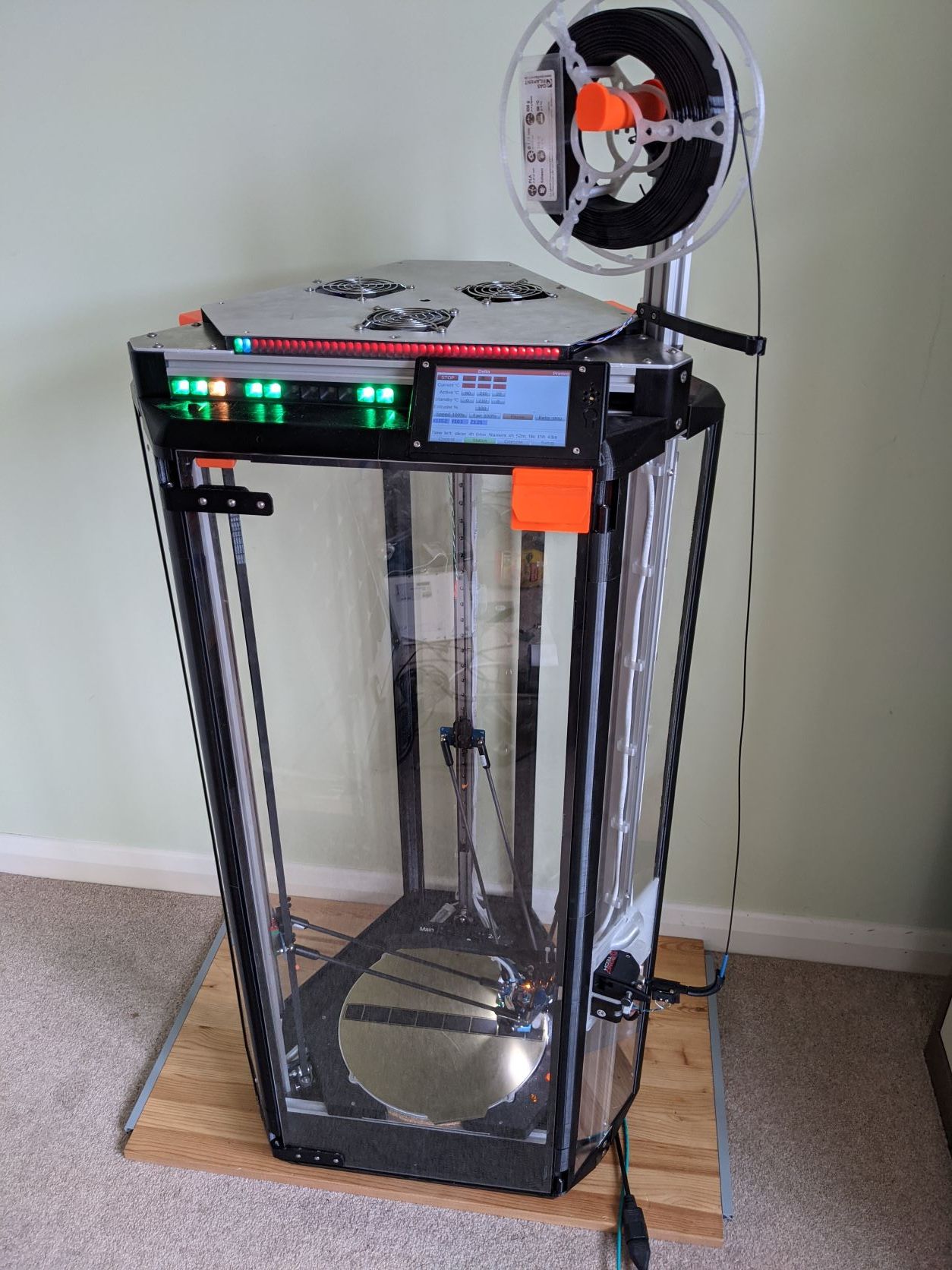
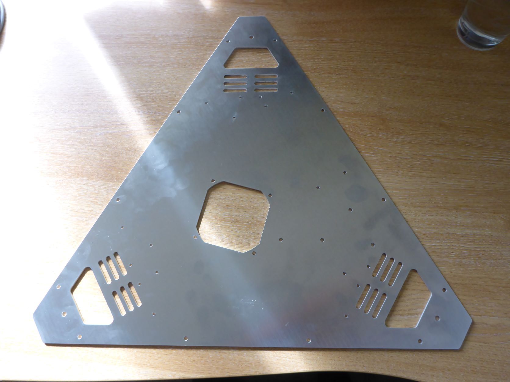
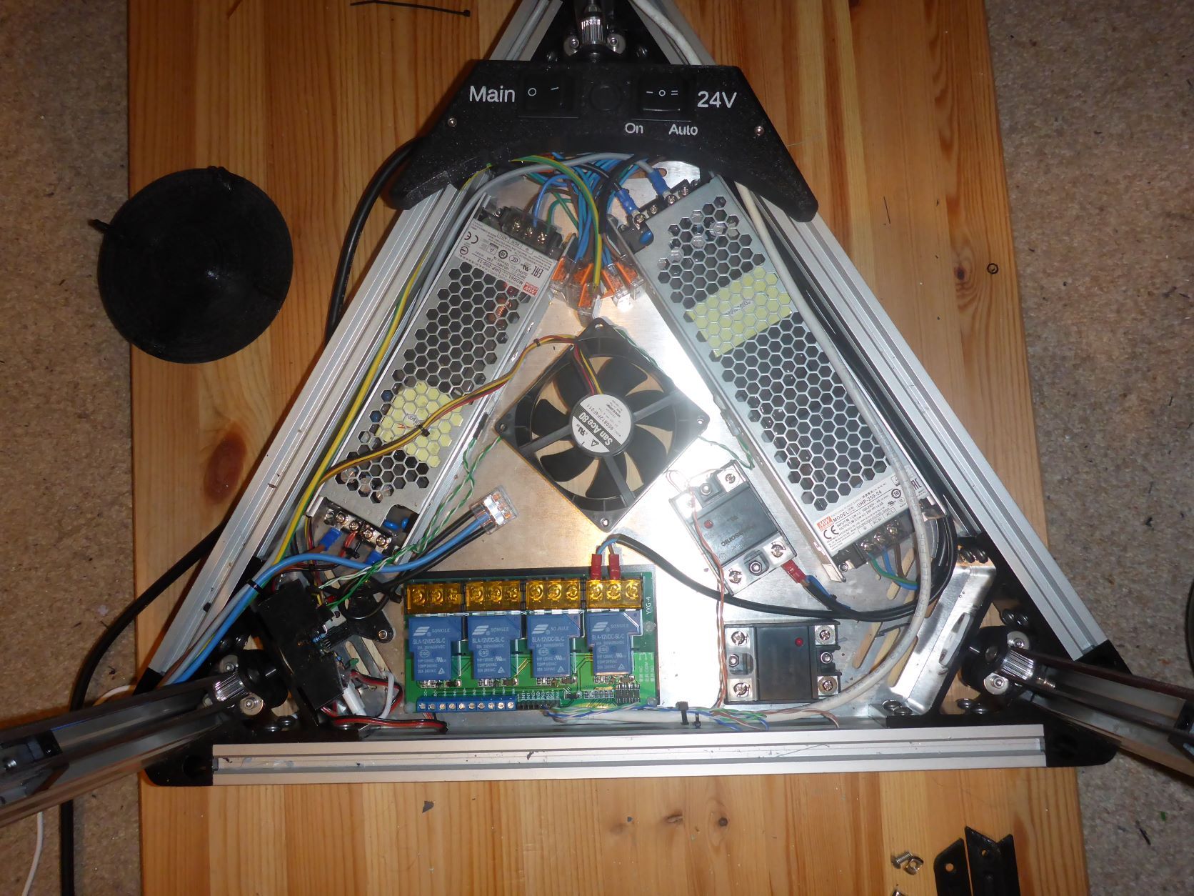
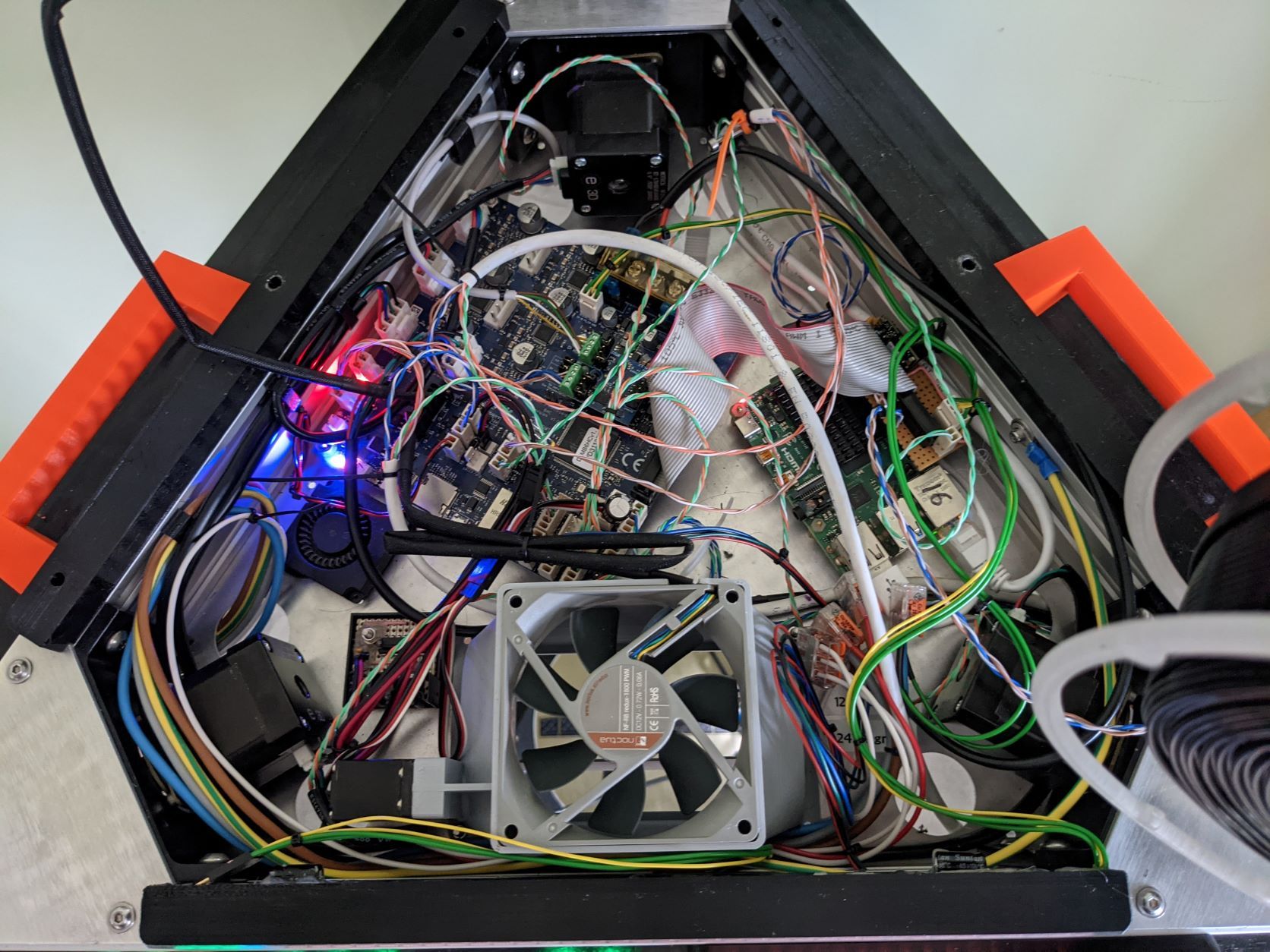
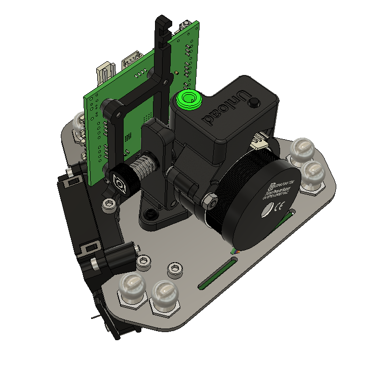
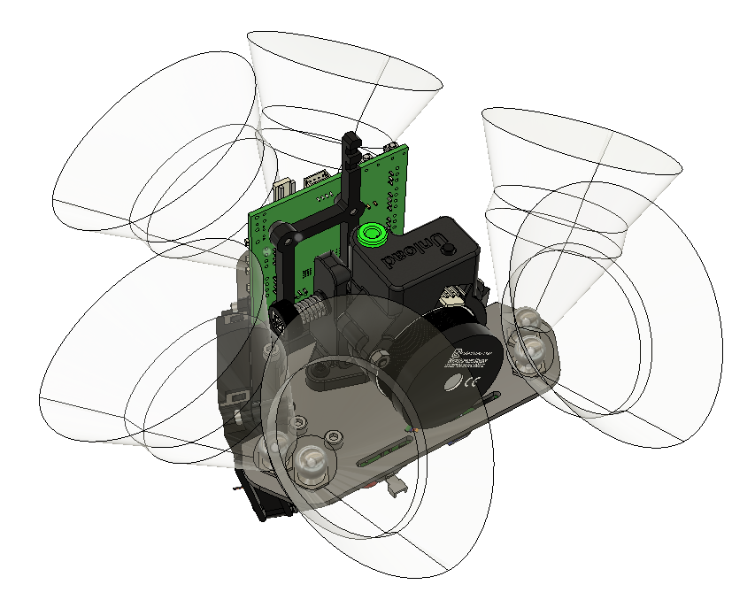
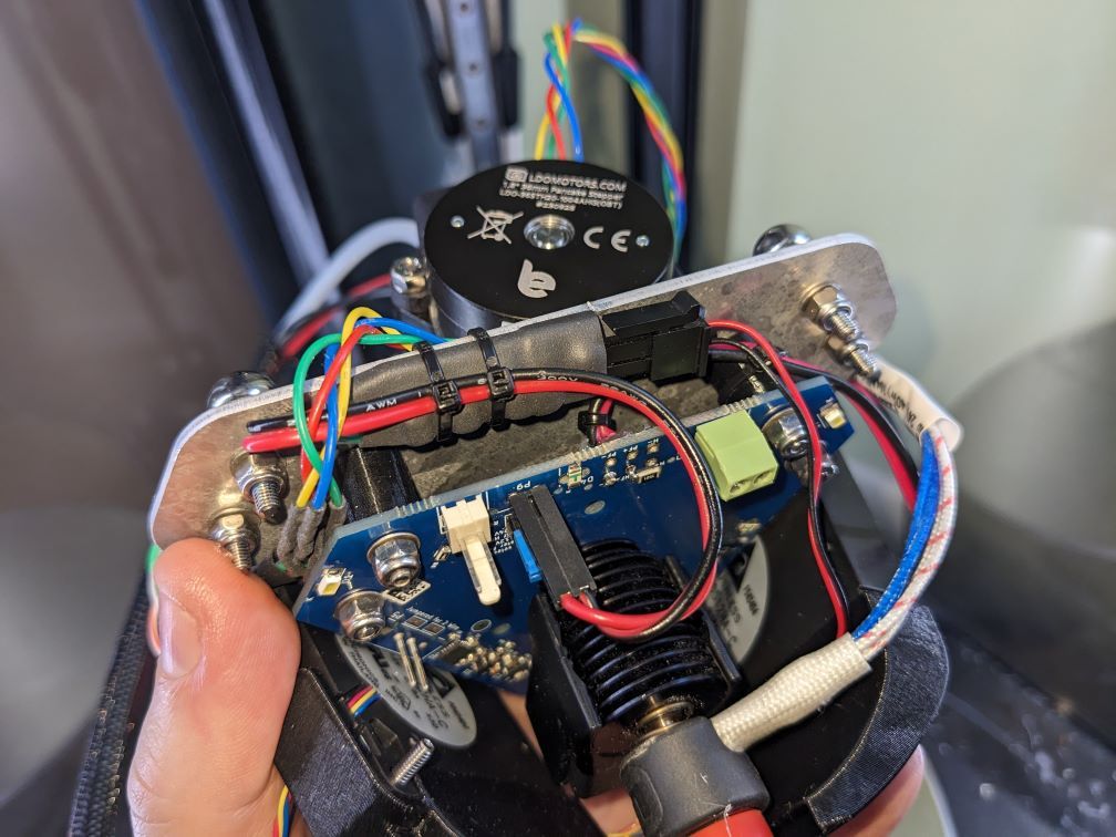
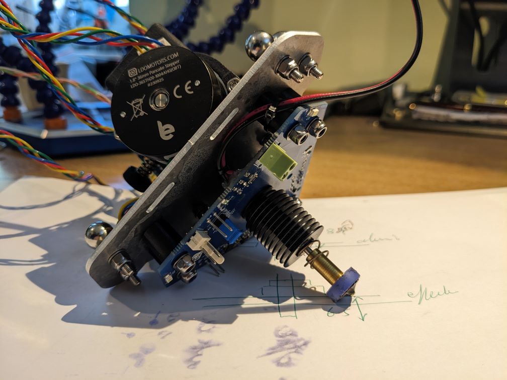
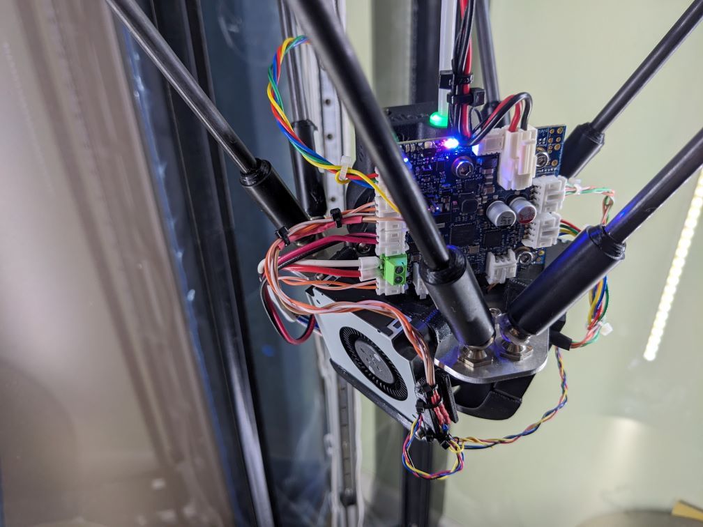
      I've been assembling a printer from some of the parts of a Prusa i3 Mk2.5, but using a Mini5 as the control board.

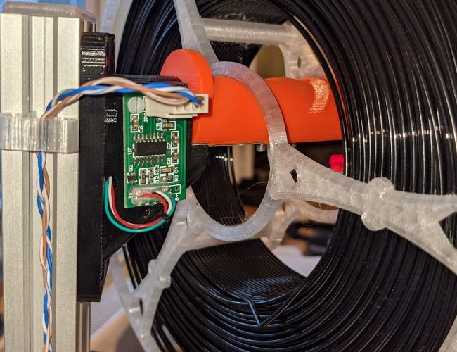
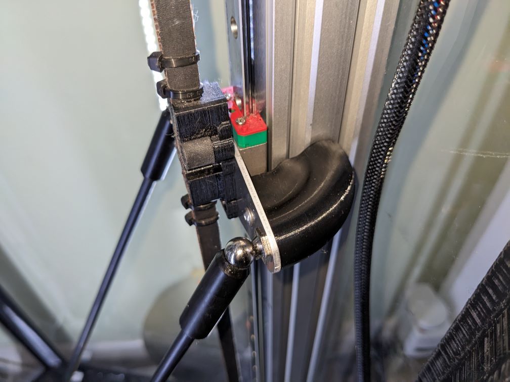
      The inductive sensor I have is a (completely genuine bought from Prusa) 'pinda' V2, which is acknowledged to have some temperature dependence, but has a built-in thermistor to permit corrections. I didn't trust the Pinda V1 at varying temperatures, and have always done all bed preheat with the printhead as far from the bed as possible to minimise heat effects.

      I should acknowledge https://forum.duet3d.com/post/302443 which specifies some thermistor parameters (100k, B=3950) and a temperature coefficient (0.02) because (spoiler!) although I now think the parameters for mine are very different from that, it was a useful part of getting to this point.

      With RRF it should be relatively easy to confirm calibration, because you can probe, heat up the probe by heating the bed (my printer is in an enclosure, so this is fairly effective), then probe again and see what happens. Indeed, the stock Prusa had a function to calibrate something like this - sitting the head just above the bed for a few minutes while it heated and periodically probing. However, it turns out to not be that straightforward.

      My first pass did exactly that - put the nozzle just above the bed, switch the bed on, probe every time the pinda gets half a degree hotter than it was and see what happens. I got this:
      2d7cf0b8-dee5-4b71-a1ef-b0ce1928e11c-image.png

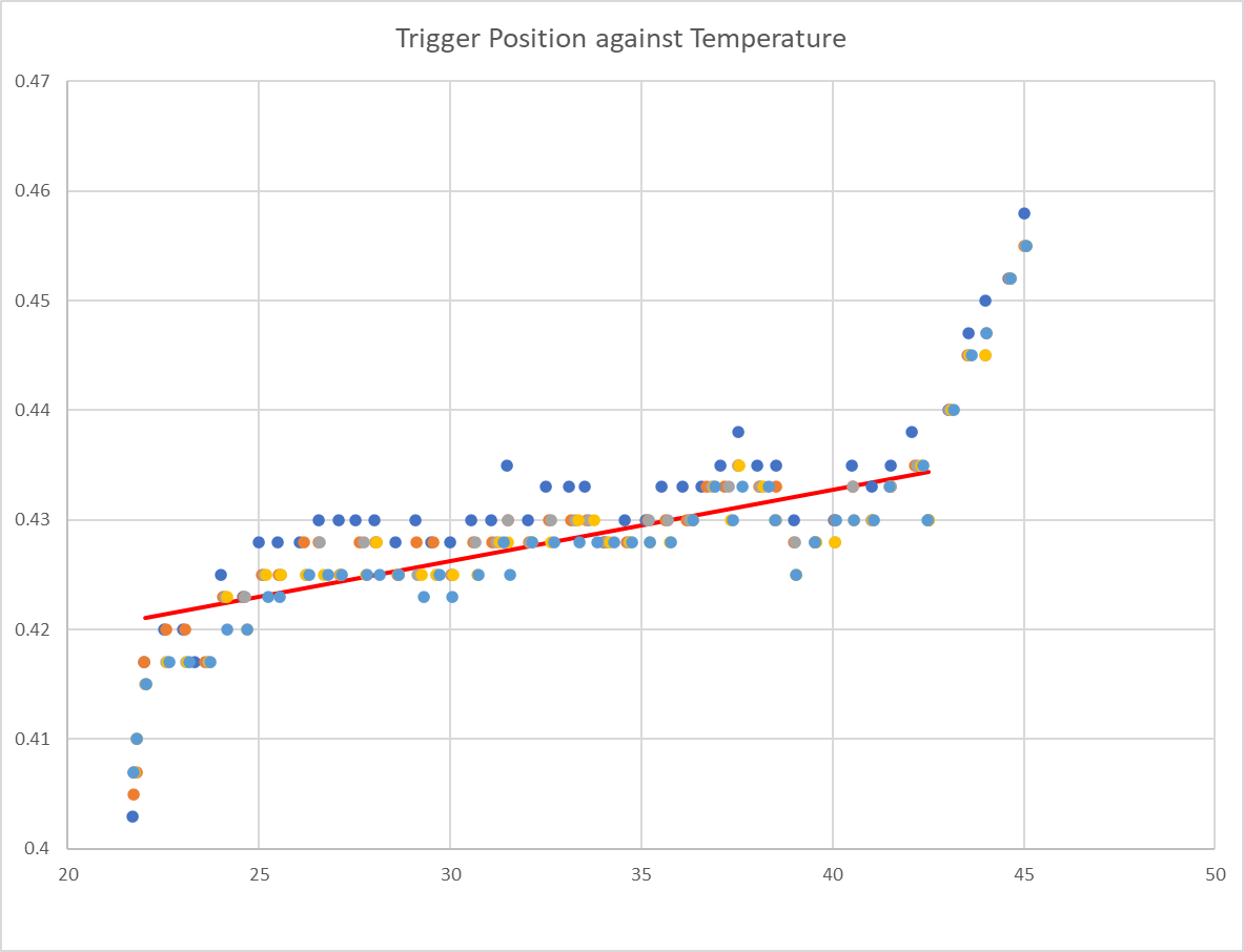
      Interesting observations are linearity-ish through the middle, but it's much lower coefficient than the post referenced above (in this case about 0.001 - one twentieth) and the non-linearity at beginning and end. After a number of runs of this I noticed something and when I return to that first data set it's there to see too. This is the graph of temperature against time for that run:
      16194bf9-6cb9-425b-8931-bda57cf7c236-image.png

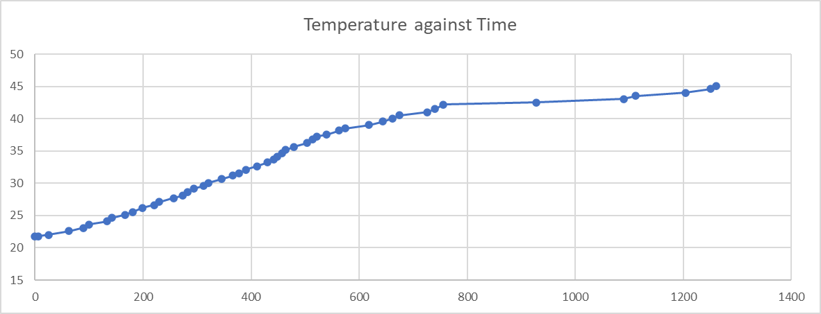
      So that dramatic change in apparent temperature coefficient from about 42 degrees correlates with a dramatic change in time it takes to get to each temperature increment. This leads me to think that the thermistor in the probe heats up faster than the electronics - so when the temperature is rising (fairly) quickly, the electronics are actually cooler than reported and so exhibit less apparent temperature dependence.

      So then I did it again. This time I coded a more complex heating algorithm - it uses PID (but not very tuned) to adjust the bed setpoint temperature as if it was the power input and tries to hold the pinda at a constant temperature for 40 minutes before taking four sets of probe readings at 5 minute intervals, with 3 probes per set and then moving on to the next temperature.

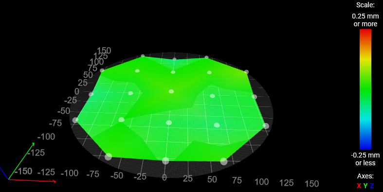
      This does of course come with the caveat that I’m assuming my bed doesn’t itself move at different temperatures. I suppose I could set up a dial gauge on it (but the only one I have has lost its spring, so not terribly useful).

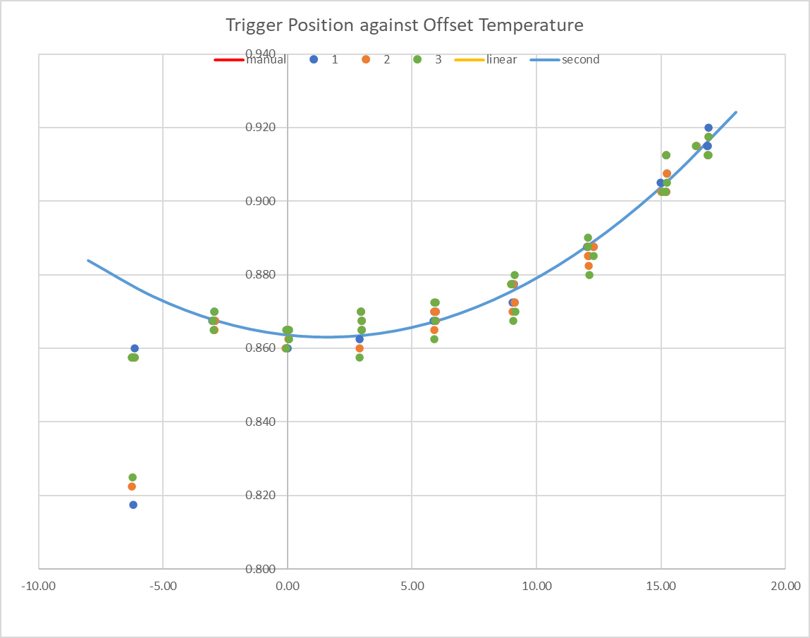
      This is fairly successful (with some cheating on the first cycle to avoid a massive over-temperature spike while the integral term initialises / stabilises) and I typically get a temperature v. time from the pinda thermistor like this (red dots are where probing was done):
      81e7832c-7da6-448e-be6a-8ba7aaaf47cf-image.png

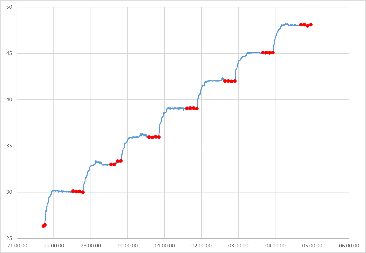
      Now I get a more consistent temperature coefficient, which is distinctly non-linear, but which matches quite nicely to a 2nd order polynomial that RRF can accommodate.
      e88557c1-0a92-49e8-aab9-009afbc9ab22-image.png

      The first readings (before the bed is heating at all) are often off the curve, but by varying degrees. I haven't come up with any good hypothesis for this. This is another run, with an unusually large first set difference.
      af8eb7da-12f7-48a2-bba0-35e07d0a0f6e-image.png

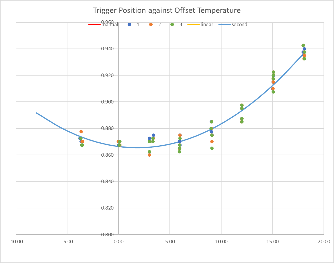
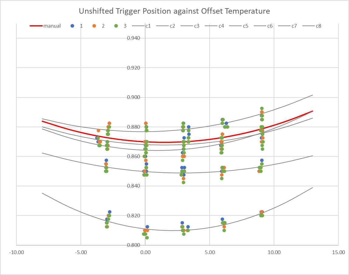
      If I neglect the pre-heating data and put multiple runs on one graph, I find that the behaviour is relatively consistent. I first discovered my homez approach was not giving me a consistent result, which manifests as all the points in the test-run matching the curve relative to each other, but offset by an absolute amount up up to 0.06mm low (i.e., the homez has apparently set up the axes too high). I’ve changed my homez to do multiple head movements much slower, and that seems to have fixed the issue.

      Also, I’ve set zero compensation for the duration of this testing, so actually the homez is setting to 0.87mm regardless of probe temperature at the time, which will introduce the error I’m trying to quantify into my testing.

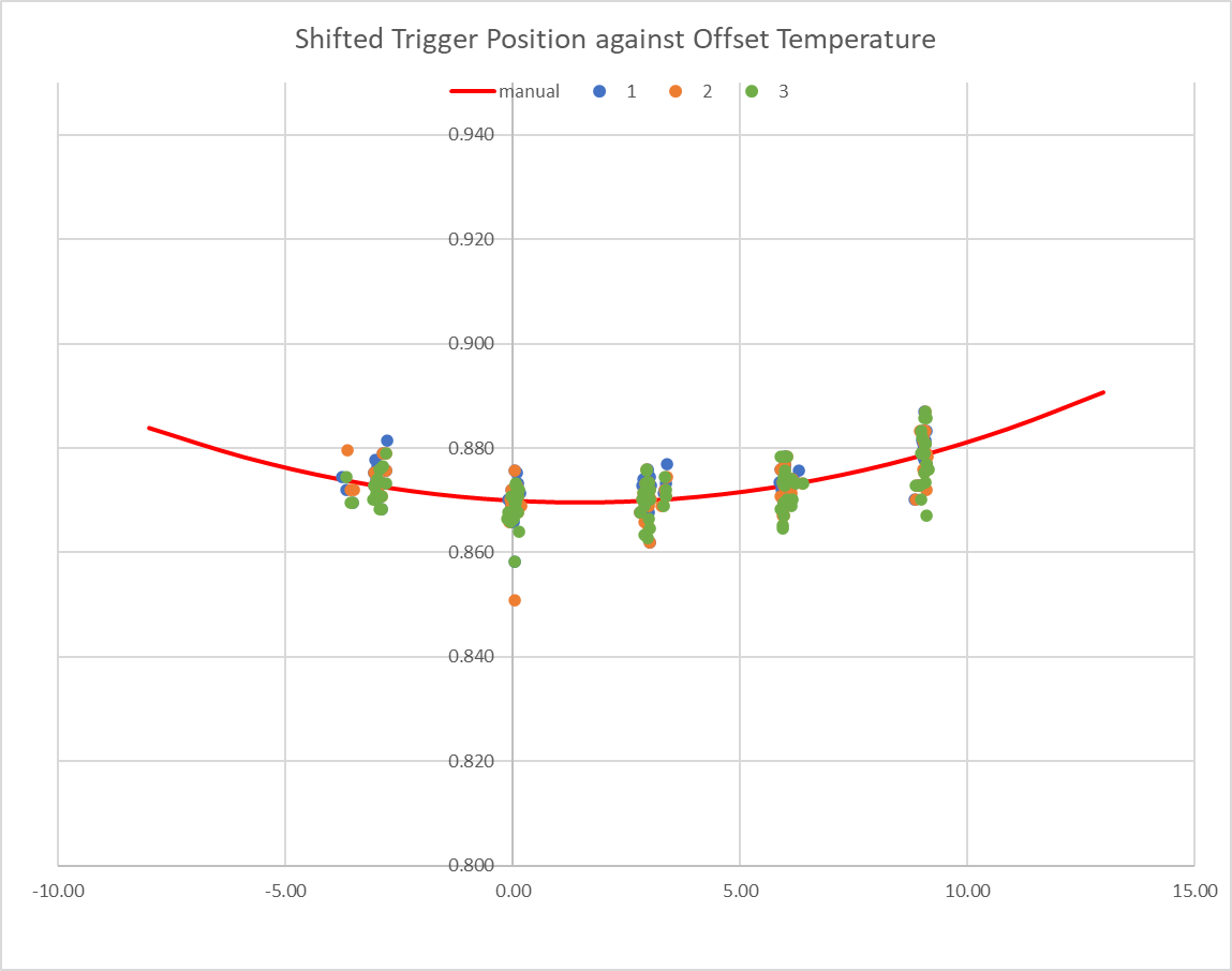
      For both these reasons, I take the data from a single test run (typically 32 G31s in eight sets of four readings at each temperature), fit a second order polynomial, find the shift that would bring the polynomial to my calibration value (0.87mm at 30C), then apply that shift to all the data in that test. When I do this, the resulting scatter across all the tests (five runs and counting) is about the same as the scatter within any one test.
      503853aa-00f7-4741-82b0-e45378fef0dc-image.png
      35f90246-c9e6-49cc-b709-65653e73635a-image.png

      I'm curious how the Prusa firmware manages to do a calibrate in a few minutes if this time dependency exists, but possibly it doesn't actually calibrate directly, and just takes some readings that it uses to adjust the built-in calibration.

      This is fairly niche information, I appreciate, but I thought I'd post in case anyone is interested. Actually, my main conclusion is that I didn’t really need to bother, because my conclusion here is that over a 15C range where I’m interested (most of my prints start with the probe at about the same temperature), the trigger height only varies by 0.01mm (ish).

      From reading on (mainly Prusa) forums, I suspect that Pinda v2 probes are possibly not only temperature-dependent but also show quite widely varying dependence – there are a number of reports of people changing probe and suddenly finding calibrating the first layer much easier or much more difficult. Possibly I’m lucky with a low-variation one.

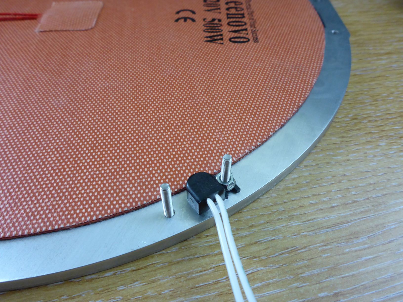
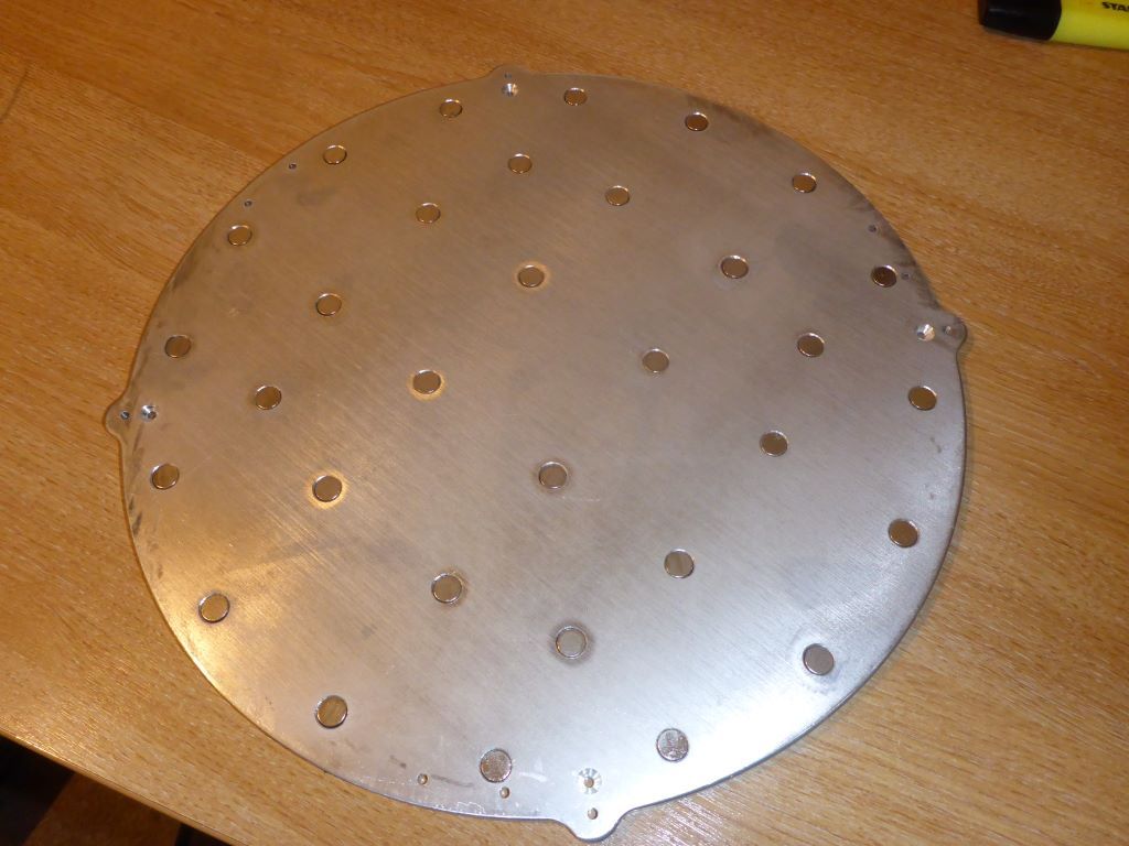
      Even without such a (hypothesised) variation, this specific data may not be relevant to anyone else, because the apparent temperature correlation is a function of the thermistor properties (I have no idea how consistent the thermistor is), the electronics actual dependency and the behaviour of the bed (i.e., my bed likely moves differently in response to temperature than anyone else's - it's initially a Prusa heated bed, but I've modified it a bit and it's not on a Prusa frame).

      Conclusion

      So the conclusion to all that is that I've got a calibrated 2nd order polynomial temperature compensation, but actually it's a small enough effect that I could do without. I'm using T-0.000470:0.000159 in my G31 config settings, which over the range 25 to 35C (where I normally am when probing the bed at the start of a print) that equates to a variation in trigger height of only 0.007mm (between max and min), or about three microsteps.

      Workings

      The rest of this is what I used to conclude the above

      This is my macros that do the calibration (you need both because probeTcalib calls probe3), note that there are configuration variables in the start of both that need setting (e.g. which sensor is the one in the pinda). As noted, I set a zero temperature coefficient for the probe before running this, but I think the lastStopHeight is reported without temperature compensation (i.e. the compensation is not applied to the stop height, it's applied to the probe offset value used to set the head coordinates) so that wouldn't actually matter.
      probeTcalib.g
      probe3.g

      This is the spreadsheet that I use to analyse a single run, but I've taken out the 32000+ rows of temperature values to shrink the file size. If anyone wants my data I'm happy to email an example - the spreadsheet with the temperature log data is about 3.5MB.
      probe T calibration - 20230304 - pruned.xlsx

      This is the spreadsheet with multiple runs overlaid. The first two cases in this are with my ‘inaccurate’ homez , resulting in a ‘large’ shift (up to 0.06mm) the others are with my new homez and shift is about a tenth of that. (For information, my Z axis is 400 steps/mm, or 0.0025mm per step).
      probe T calibration - combined limited.xlsx

      posted in Tuning and tweaking
      achrnundefined
      achrn
    • Another weighing filament holder returns

      I think there is maybe one other person on the planet using my filament weighing plugin (https://forum.duet3d.com/post/253602), but notwithstanding that, this updates it for firmware 3.5.1 and a fresh Bookworm DuetPi. There's also some tidying up internally.

      This is the plugin file (but you will need to take the .txt off the end of this file - I'm circumventing the forum restrictions): WeighFilament.zip.txt

      WARNING

      This one is not as good as the old one on 3.4, because I can't get http endpoints to work on 3.5.1, so I can't put a continuously updating display on the DWC screen. However, this one sets up a global variable with the weight value in it, so you can define a macro containing e.g. M291 P{global.filWeight^"g filament on spool"} R"Filament Weight" and get the weight at the click of a button, so it's useful.

      I do intend to revert to the old functionality when I can figure it out. The problem might be that I'm jumping the gun - I'm using pre-release dsf-python-3.5.0.2rc2 with 3.5.1 RRF and DWC, and that's not a combination that's listed as compatible at https://github.com/Duet3D/dsf-python/releases.

      For now, this plugin is purely DSF, no DWC component at all.

      What it does

      It connects a HX711 load cell amplifier direct to a Pi so you can build a load-cell into the spool holder and have a report of filament weight on the spool. The weight of filament is written into a global variable (global.filWeight, but that's configurable) for you to do whatever with.

      A python3 DSF routine takes one new weight reading every three seconds (configurable), and averages over the previous 12 readings (configurable). It uses a simple IQR-based filter to disregard outliers in the data, which should eliminate the odd faulty readings. It tries to spot step-changes (e.g. lifting the spool off the holder) and if it does, it reads a whole new set of 12 readings at once, so you get a quicker update of weight (around ten seconds) and it should jump straight from previous weight to new weight without sliiiiding from one value to the next. The global variable is only updated if the weight is more than 5g different to what it last reported (threshold is configurable). The aggressiveness of the IQR filter is configurable too.

      There are obvious (and explained) values in the start of /opt/dsf/plugins/WeighFilament/dsf/weighfilament.py you can change to modify all the configurable items.

      There is a helper script that records tare weights and calibration values.

      Hardware

      Hardware is a HX711 breakout and single-point load cell. Mine is an ebay-cheap-special 3kg cell, 13x13x80, and the cheapest available green breakout. The load cell plus board is probably only £5 on ebay. Connect loadcell wires to the breakout (loads of instructions on probable colour scheme the web) and then breakout to a 3.3V pin, a 0V pin and two GPIOs on the Pi - the code assumes DAT to GPIO5 and CLK to GPIO6 (configurable). Note that the HX711 has two hardware channels - channel A can do either 128x or 64x gain and B can do 32x gain - you need to connect the cell to the correct channel for the gain you are using.

      weigh_spool.png

      spoolholder_s.jpg

      Installation and Calibration

      You need some python libraries. At a command prompt: sudo apt install python3-numpy. The previously required python3-rpi.gpio and python3-setuptools seem to already be part of the latest DuetPi image.

      You need to download and install the dsf-python from https://github.com/Duet3D/dsf-python/releases. As noted above, I'm currently using dsf-python-3.5.0.2rc2 which is pre-release. I haven't tested other versions. Having downloaded and unpacked you cd into the library top folder and sudo python3 setup.py install.

      You need to download and install the HX711 library from https://github.com/tatobari/hx711py This is pure python and relatively straightforward. Having downloaded and unpacked you cd into the library top folder and sudo python3 setup.py install. Note that the author has done some (relatively) recent changes to the library - I'm not using the new functionality, which is mainly focussed at increasing the speed of reading - the old functionality works fast enough for this use case.

      To install the plugin drop the zip onto the 'Install Plugin' button in Plugins / external plugins in DWC - but DO NOT START the plugin yet.

      The plugin won't create the necessary global variable, only update an existing one, so you need to add creation of the variable to config.g, e.g. with the following. The value you set here doesn't matter. You can use a different variable name, but in that case must edit the value near the start of /opt/dsf/plugins/WeighFilament/dsf/weighfilament.py to match.

      if !exists(global.filWeight)
          global filWeight = 0
      

      You need to calibrate the routine before use. The plugin has a helper script to do that, and it's easiest to put this into /usr/local/bin so you can run it directly. At a command prompt run sudo cp /opt/dsf/plugins/WeighFilament/dsf/weigh /usr/local/bin and then sudo chmod a+rx /usr/local/bin/weigh.

      With nothing on the spool holder at a command prompt run weigh zero, this records the tare reading of the holder alone.

      Then you need something of a known weight not dissimilar to a spool of filament (preferably nearing the end) on the holder - I use a 200g weight - and run weigh calib. It will ask you what the weight is.

      Then preferably put an empty spool on the holder and run weigh spool. If you don't have an empty spool but do know what one weighs you can run weigh manual and enter a weight value.

      Actually, you can abbreviate the weigh options to the first letter, and scatter '-' around too - instead of weigh zero you can weigh z or weigh -z or weigh --zero or weigh zipadeedoodah etc.

      Some semi-cryptic entries should now have shown up in the weighfilament_calib.txt file in the system directory.

      You can re-run any of these (e.g. when you change to a spool with a different empty weight), but you must stop the plugin first. There is no locking, and the script and plugin will scramble each other's communication with the HX711 if they run simultaneously, normally resulting in a hang or garbled data. The calibration file grows forever, if you do a lot of resetting the calibration you can open it and delete older lines - the routine just uses the last of each 'zero', 'calib' and either 'spool' or 'spoolwt' lines it finds in the file.

      If you get wildly varying (or complete garbage) answers or the script hangs, the plugin is probably running. Stop the plugin before running the script. Also, the plugin only reads the calibration file on startup - so you need to start the plugin after changing calibration values for it to get the new values anyway.

      However, there is apparently the possibility of problems with bit ordering and byte ordering which can also lead to garbage values - if you still get garbage values see the discussion on the HX711 library github page and make changes in definitions near the top of both the helper script and the weighfilament.py file in the plugin zip file.

      After all that you should be able to start the plugin. Apart from 'Status' changing to 'started' nothing visible will happen, but if you look in the object model browser or run M291 P{global.filWeight} you should get a weight. I have a macro as defined near the top of this posting to prettify it a bit.

      posted in Plugins for DWC and DSF
      achrnundefined
      achrn
    • Light relief - hardware bug or feature?

      So I put my 3D printer bed back together, complete with tidy covers around the print bed, and found a slight hardware bug remarkable feature:

      I can do a remote hard power-off:

      G1 X0 Y140 Z0.5
      G1 X-50
      

      does this: https://player.vimeo.com/video/487182136

      posted in Off Topic
      achrnundefined
      achrn
    • Another weighing filament holder

      In what is undoubtedly the biggest sofware release of the day I have implemented another filament weighing plugin for a system with an attached Pi.

      Actually, half of it is a direct lift of Resam's plugin described at https://forum.duet3d.com/post/241194. I have taken the DWC plugin from that but written a new python DSF routine. Mine is for a HX711 directly connected to the Pi. Resam reports getting noisy / faulty readings with an HX711 connected directly, but I get very few - this may be subject to all sorts of vagaries of wiring etc.

      My DSF routine uses a simple IQR-based filter to disregard outliers in the data, which should eliminate what faulty readings do occur. It takes one new reading every three seconds, and averages over the previous 12 readings. It tries to spot step-changes (e.g. lifting the spool off the holder) and if it does, it reads a whole new set of 12 readings at once, so you get a quicker update of weight (around ten seconds) and it should jump straight from previous weight to new weight without sliiiiding from one value to the next.

      I also have a helper script that records tare weights and calibration values.

      Hardware is a HX711 breakout and single-point load cell. Mine is an ebay-cheap-special 3kg cell, 13x13x80, and the cheapest available green breakout. Connect cell wires to the breakout (loads of instructions on probable colour scheme the web) and then breakout to a 3.3V pin, a 0V pin and two GPIOs on the Pi - the code assumes DAT to GPIO5 and CLK to GPIO6 (but there are parameters in the top of the .py file in the zip if you want to pick different ones). I created a spool holder in OpenSCAD, and because my printer is a delta the spool axis is at 30 degrees. Also beware, this holder is only 80mm wide (between upstands).
      weigh_spool.png
      weigh_spool.scad

      spoolholder_s.jpg

      How it works:

      The plugin creates an endpoint on the printer at http:<machine name or IP address>/machine/filament-load-cell/reading. The endpoint shows the latest measured filament weight (or a comment about why not). The DWC plugin periodically grabs the text from that endpoint and inserts it into the banner of the DWC page. In this version, the code of the endpoint is by me, the code that sticks the text into the DWC page is by Resam.

      The plugin is here (but you'll need to remove the .txt - that's me circumventing the forum system): WeighFilament.zip.txt

      I strongly suggest unzipping it and reading through before installing so you know I'm not doing something nefarious with your printer.

      The helper script is here: weigh.txt (again, you probably want to rename it without the .txt)

      Note that I don't consider myself much better than 'can make myself understood' in python, and I despise it, and my coding is not 'pythonic'. Feel free to improve it. It's MIT licence. I don't mind what you do with it, I don't warrant it fit for anything, if it breaks anything you get to keep the pieces.

      Installation:

      You need some python libraries: sudo apt install python3-rpi.gpio python3-numpy python3-setuptools (others too, but they are probably already installed).

      You need to download and install the HX711 library from https://github.com/tatobari/hx711py This is pure python and relatively straightforward. It appears to be written for python2, but runs happily under python3 as well, so having downloaded and unpacked you cd into the repository folder and python3 setup.py install.

      Enable the plugin service on the Pi. See https://forum.duet3d.com/post/219064 (but that says you won't need to do that soon). (Also, I don't think I put apparmor in my cmdline.txt, and it seems to work for me).

      The helper needs to write to a state file somewhere. sudo touch /var/lib/misc/spoolweigh.txt and sudo chmod 666 /var/lib/misc/spoolweigh.txt. You can put it elsewhere but you'll need to edit both the helper script and the weigh_filament_endpoint.py file in the plugin zip file. This file will grow every time you calibrate or use a different weight spool. You can just prune older lines - the plugin uses the last relevant content it finds - it needs a 'zero' line, a 'calib' line and either a 'spool' or a 'spoolwt' line.

      Do the initial calibration before running the plugin. This is all by the command line on the Pi, so you need a command terminal / window / whatever. Put the helper script somewhere, make it executable, and then you can run it. First, with nothing on the spool holder run weigh zero, this records the tare reading of the holder alone. Then you need something of a known weight not dissimilar to a spool of filament (preferably nearing the end) - I use a 200g weight - and run weigh calibrate. It will ask you what the weight is. Finally, preferably put an empty spool on the holder and run weigh spool. If you don't have an empty spool but do know what one weighs you can run weigh manual and enter a weight value. You can re-run any of these (e.g. when you change to a spool with a different empty weight), but you must stop the plugin first. There is no locking (for various reasons, not least my lack of competence), and the script and plugin will scramble each other's communication with the HX711 if they run simultaneously, normally resulting in a hang or garbled data.

      Actually, you can abbreviate the options to the first letter, and scatter '-' around too - instead of weigh zero you can weigh z or weigh -z or weigh --zero or weigh zipadeedoodah etc.

      If you get garbage answers or the script hangs, the plugin is probably running. Stop the plugin before running the script. (Also, the plugin only reads the file on startup - so you need to start the plugin after changing calibration values for it to get the new values anyway). Stop the plugin before running the script.

      However, there is apparently the possibility of problems with bit ordering and byte ordering which can also lead to garbage values - if you get garbage values see the discussion on the HX711 library github page and make changes in definitions near the top of the helper script and the weigh_filament_endpoint.py file in the plugin zip file.

      The helper also does weigh filament to report the weight of filament on a spool on the holder, weigh gross to tell you the weight of everything on the holder (i.e. typically spool plus filament), weigh quick / weigh quiet which does fewer readings and does less chit-chat, weigh raw which gives you the rawish data coming back from the HX711 and does no outlier filtering or conversion to weight units. Probably use these to check it's behaving itself before using the plugin.

      Once the zero, calibrate and spool are done, you can install the plugin by dropping the .zip file onto the 'UPLOAD & START' button in DWC. If I haven't forgotten a critical step above, the weight of filament on your spool should appear alongside the machine name (here it is on my imaginatively named delta printer):

      5c526512-c794-4002-a3ee-4899adb49443-image.png

      It reports to the nearest 0.1g, but don't confuse resolution with accuracy. I find the reported weight wanders around by about 2 or 3g day-to-day. Also, note that unless your filament exits the spool horizontally, the vertical component of pull force on the filament contributes (positive or negative) to the weight reading whenever the printer is extruding.

      posted in Plugins for DWC and DSF
      achrnundefined
      achrn
    • a python daemon

      This is a Duet Software Framework (DSF) plugin that duplicates similar behaviour to 'daemon.g', except that it runs python code (python 3) on an attached Raspberry Pi when the printer is running SBC mode. The python code has access to a recently-updated copy of the machine object model, and can set the interval to the next time the code runs.

      A python3 DSF routine runs every 'loop interval' seconds, looks for a specified file in a specified location (by default daemon.py in the printer sys folder, which is at /opt/dsf/sd/sys/ on the Pi - these can be changed but note that the filename must end in '.py'). If the file exists, it runs the function 'loop()' (if it exists) from within that file each interval. If the file has changed (or appeared) since the last check, the function 'setup()' (if it exists) from the file is run first immediately before running loop().

      That is, the daemon.py file functions are somewhat like the functions in an arduino sketch - setup() is run once, and then loop() is run repeatedly. However, in this case, loop() is run only periodically, as defined by the 'loop interval'.

      Note that the functions run 'on the dot', so if the interval is set to 60 (i.e. 60 seconds, i.e. 1 minute) loop() runs every minute on the minute, whether the function takes milliseconds to complete, or 59 seconds to complete. However, it runs on the next occurrence of the time interval, so if the interval is set to three seconds, but the function takes four seconds to run, it will actually be run every six seconds: starts at ...0, finishes at ...4, the next multiple of three is ...6 so it runs then and finishes at ..10, the next multiple is ..12 so it runs then and finishes at ..16 and runs again at ..18, etc.

      Both functions are called with a dict-of-dicts-of-... parameter that contains the entire object model at the current time (though it can be up to about 2 seconds out-of-date). Thus, within the python functions, object model elements can be accessed with e.g. print(object_model['heat']['heaters'][1]['active']) (assuming the parameter has been named 'object_model' in the function definition).

      Both functions can change the current loop interval setting by returning a value that can be interpreted as numeric and greater than zero. It can be fractional, but values less than about a second are not recommended.

      The whole daemon.py file is (re-)imported each time the routine notices it having changed, so whatever is outside any functions will run once at import (before setup() is run) so can include imports and global variable definitions.

      Thus, for example, daemon.py could be:

      # example daemon.py file
      #
      
      # setup() is called once, with dict-of-dicts of object model as sole parameter
      # if this function returns a value that can be interpreted as a number > zero
      # the loop interval will be set to that value (seconds)
      
      def setup(om):
          global tlog
          tlog=open('/opt/dsf/sd/sys/tempslog.csv','w')
          print (om['boards'][0]['uniqueId'], file=tlog)
          return(30)
      
      # loop() is called periodically, with dict-of-dicts of object model as sole parameter
      #
      # at each next occurrence of a multiple of the interval since the epoch,
      # the object model dict is updated and then this function is run
      #
      # if this function returns a value that can be interpreted as a number > zero
      # the loop interval will be changed to that value
      
      def loop(om):
          global tlog
          print(om['state']['time'], end='', file=tlog)
          for h in om['heat']['heaters']:
              print (','+str(h['current']), end='', file=tlog)
          print(file=tlog, flush=True)
      
      
          if om['heat']['heaters'][1]['active'] > 0:
              return(3)
          else:
              return(30)
      

      This will create a 'tempslog.csv' file in the printer sys folder, and log the time and the temperature of each heater into it in CSV format. If heater 1 is set to a target value greater than zero, the log will update every three seconds, otherwise it will update every 30 seconds. If you make any change to daemon.py (including e.g. simply touch daemon.py at a command prompt on the Pi) the plugin will notice a change to the file, and re-run setup(), creating a new tempslog.csv and obliterating the previous one. You can also simply rename daemon.py to something else to stop it running, and name it back to daemon.py when you want the logging to run, or stop and start the plugin.

      (If you didn't want 'obliterating the previous one', it would be a case of changing the file open command in setup() to tlog=open('/opt/dsf/sd/sys/tempslog.csv','a') so you append to the .csv file rather than write to it.)

      Multiple loop functions can be defined, with names in the format loop<nn> where <nn> is an arbtrary integer, e.g. def loop13(om):. These will run every nth loop (e.g. every 13th loop). At each interval the bare loop() function runs first, and then each relevant loopn() function is run in the order that they are found in the daemon.py file. For example, to add a line of headers repeated every 20 lines of data, you could add to the example above:

      def loop20(om):
          global tlog
          print ('"time               h0    h1    h2"', file=tlog)
      

      Although loop() runs before any loopn() function, you can circumvent that by defining loop() as just pass and then defining e.g. a loop20() earlier in the daemon.py file than a loop1(). On most increments loop() will go first and do nothing then loop1() will run, but on every twentieth increment loop() will run and do nothing then loop20() and finally loop1() will run.

      As a further variant on this, you can name a loopn() function beyond the number, so two different functions that both run every 20 intervals could be named loop20a() and loop20b() (or loop20tweedledum() and loop20tweedldee(), or whatever).

      All these additional loopn() functions also need to take a single parameter (which will be the object model) and can change the interval timer by returning a numeric value.

      As implied above, the daemon.py file can be removed and replaced or changed at will and the plugin should handle it gracefully. It will fail and the plugin will stop running however if while editing the file it's saved in an intermediate non-python-grammatical state at the moment the plugin tries to run it.

      To see messages relating to the plugin run journalctl -u duetpluginservice -f at a command prompt on the Pi.

      The logged messages can be greatly increased by setting 'verbose' and 'vTS' to True in the top of file /opt/dsf/plugins/PyDaemon/dsf/pydaemon.py on the Pi. 'vTS' adds a microsecond-resolution timestamp to each logged comment.

      It's not very extensively tested.

      To install:

      You need dsf-python installed. At a command prompt on the Pi: sudo pip3 install --break-system-packages --pre dsf-python. It will moan about how you should be using a virtual environment instead, but should work. I haven't done any testing with virtual environments. Note the '--pre' is because dsf-python is currently pre-release for 3.5 firmware.

      Otherwise I don't think it needs any very non-standard modules - it uses json, time, sys, pathlib, importlib, re and inspect, which are probably all in by default (but I can't swear to that). If something complains you might need to install the relevant module.

      You should read the source to ensure it's not doing anything nefarious. It's about 200 lines of pure python (and about 100 lines of comments).

      To install the plugin drop the zip onto the 'Install Plugin' button in Plugins / external plugins in DWC and click the Start button. Then (or previously) create your daemon.py file in the printer sys folder (on the Pi: /opt/dsf/sd/sys)

      As usual, I warrant nothing. It's not even fit for any purpose.

      You'll need to remove the .txt, this is just me circumventing the forum systems: download: PyDaemon.zip.txt

      posted in Plugins for DWC and DSF
      achrnundefined
      achrn
    • A delta with colourful lights

      Back in early 2020 I started building a new 3D printer (I already had a Prusa Mk2) and I've just finished all the things I had in mind when I started, so while I hesitate to say it's finished, here it is.
      PXL_20211017_141356220.jpg

      In essence it's a fairly standard delta, though built with genuine brand components from the 'good' end of the range, so it's Duet MB6HC plus smart effector (I ordered that just before the mini 5+ was announced!), Hiwin rails, Gates 9mm belts, Haydn Huntley carbon rods, Bondtech BMG, Meanwell PSUs, E3D V6 (copper block, titanium heatbreak), magnetic bed. Suppliers are from among the usual suspects (RobotDigg, Ooznest, E3D, Farnell, Digikey) plus www.lasermaster.co.uk (no relationship other than happy customer) who did all the aluminium laser cutting - I've used them for mild steel, stainless and aluminium in all sorts of sizes and thicknesses (including some very small orders) and always been happy.
      P1100017.JPG

      PSUs are in base, along with SSR for the mains heated bed. I have a 350W 24V and a 200W 12V - the latter drives a 5A POL DC-DC convertor at the Raspberry Pi to generate 5V for the Pi, the Duet board and the LEDs. The 24V PSU is powered via a real relay (I don't like putting PSUs on SSRs - but that's just a superstition of mine). Both PSUs are fanless, but the bottom aluminium plate is deliberately chunky (as a heatsink) and there's an arduino (actually a teensy) with thermistors on each of the PSUs which runs a fan if required. There's a spare SSR in case I heat the enclosure in future.
      P1100189.JPG

      Duet, Pi, steppers and a vent for the enclosure are in the top. The top enclosure has a single cooling fan blowing air in direct onto the stepper drivers, and a small centrifugal fan blowing air across the underside of the MB6HC. I thought the Pi might want a fan, but it hasn't - there's a largish heatsink on the processor, but it doesn't get much above 55C. My wiring will probably give the voron crowd conniptions, but I'm working on the basis that parallel wires risk cross-talk (honest).
      PXL_20211017_143313682.jpg

      The vent for the enclosure has some servo-driven blades. Daemon.g opens and closes it just below the temperature when the fan cuts in.
      PXL_20211017_143415930.jpg
      PXL_20211017_143341177.jpg

      There's a spool holder with built-in weighing load cell so I get a report of how much filament remains - I've posted about that recently at https://forum.duet3d.com/topic/25419/another-weighing-filament-holder

      There are two rows of LEDs (actually, one row of 40x SK9822 and a row of 12x APA102, and they are joined end-to-end as one string) to provide status information from across the room. One row gives me a progress bar (showing heater 0 and 1 when they are heating and file progress when the heaters are at temperature) and the other row gives me status of heaters, fans and power. Heater lights slide from blue if the heater is more than a few degrees below set-point through green at set-point to red if it's more than a few degrees above set-point. Fan lights are just on green if the fan is on (but I can set them to show varying colour with PWM duty). The power lights likewise change colour if the voltage deviates by more than 0.5V from where it's supposed to be.

      Heater progress bars grow form each side to meet in the middle, so this tells me the nozzle is about a third of the way to temperature and the bed is two-thirds. Reading across the second row I see that two heaters are cold (blue), one is OK (the enclosure is always OK if it's not too hot), there's one fan on, the 24V is good and the system is on:
      PXL_20211017_120619653.jpg

      File progress is just one left-to-right bar, so here it is having barely started on a file (actually about 3.5% - green is a 'full' slot and blue is a fractional, sliding from dim dark blue through bright cyan to green), and here nozzle and bed heaters are OK, the enclosure is hotter than it should be, three fans are running (print cooling, hot end, electronics enclosure), the 24V is good and the system is on:
      PXL_20211017_141431165.jpg

      The lights script is set up as a systemd service, so runs automatically on boot.

      If I'm not across the other side of the room, there's also a PanelDue 5i, as you can see.

      The enclosure is illuminated by white LEDs down the back side of the left and right legs (so flood the interior when on), but it doesn't really need them. They are just switched by the rocker switch you can see near the LEDs. The front door is on a magnetic catch and opens to 120 degrees, but can also just lift off the hinges.
      PXL_20211017_132634255.jpg

      posted in My Duet controlled machine
      achrnundefined
      achrn
    • RE: Thermostatic servo control?

      This is my prototype.

      I've had problems with enclosure overheating before (at least, that's what I blamed my problems on), so I'm maybe oversensitive to it, but my thinking was an extract fan at the top of the enclosure could draw out hot air, but that a fan alone at the top of the enclosure would act as a chimney even when I wanted the air to stay put, so I wanted some means to block that convection.

      However, I emphasise it's all just hypothetical speculation at the moment - the printer and enclosure isn't built yet.

      Here it's just on a servo tester, but (as noted up the thread) I have had it running on the Duet.

      This is printed in PLA - it would want something more robust for a high temperature enclosure, or your shutter blades would droop into the enclosure. You might be able to laser cut them from aluminium though and put a bolt through the gears as the pivot, if you want a decent temperature - they are three flat parts slotted together.

      P1090968.jpg
      P1090971.jpg
      P1090972.jpg

      posted in General Discussion
      achrnundefined
      achrn
    • RE: Duet3, microswitch endstops - why connect GND to io[x].in?

      @piotrkmiotczyk there are layers and layers of 'why'.

      Why you connect a homing switch on a 3D printer so that it's normally 'on' (ie the input is normally tied to ground) is as chrishamm says - so that if it becomes disconnected the machine stops because it thinks it's at the endstop.

      Why the 'normally on' is to ground (rather than to +ve supply) is because that's how the Duet boards are designed - there's a pullup resistor on the input so a disconnected switch goes to +ve (actually 3.3V), so you need to arrange the switch connected to ground (0V). See e.g. this snippet from the Mini5 schematic:
      289de2c5-7491-4cc3-b4b3-ef87322449d0-image.png
      Here IO_0 to the left is what goes to the chip, and IO_0_IN to the right is what goes to the pin on the connector. The R117 is the pullup resistor, so if the switch is open the chip 'sees' 3.3V, and if the switch is closed (and connected to 0V) the chip 'sees' 0V. If you connected the switch to 3.3V, the chip would always 'see' 3.3V.

      Why the boards are designed that way is (probbaly) because that's the normal way it's done - most microprocessor switch inputs are configured this way, with a switch and resistor arranged that when open the chip sees +ve supply due to a pullup resistor and the switch connected to ground so that when the switch is closed the chip sees 0V. See most Arduino or Raspberry Pi or similar introduction to electronics tutorials - this is how it's normally done.

      Why this is normal is - dunno. Possibly it's because you more normally have multiple 0V points and lines on a board so it's often easier to get a 0V wire / signal to a switch than it is to get a +ve supply wire. There's often no really good reason - if you were designing the circuit yourself you could use a switch with a pull-down resistor and the switch connected to +ve - then the chip would see 0V when the switch is open, and +ve supply when the switch is closed.

      Some chips have built-in pullup resistors, so with this configuration you don't need a separate external resistor, but I think that's mainly because this is the normal way it's done. That is, the chip designers have done that in reaction to this being the normal approach, not that this is the normal approach because that's how the chips are designed. (Some chips have both pull up and pull down - and some have differnet strengths in each direction, but again, I think that's a result not a cause.)

      Also, many (and I think probably most) configuration inputs to chips are arranged like this so 0V means 'active' - for example chips that have a 'select' line to make them do something are often/usually designed so that making that input 0V selects them. It will normally be shown as 'CS' with a line across the top of letters - meaning 'chip select active low' (because the letters are below the line, ie low). Or reset lines are often designed to reset the chip when the input is forced to 0V. The chips on the Duets show that too, see e.g.:
      f921d889-c671-41c0-80d3-993e2e93d4f4-image.png
      So here, the chip resets if that input is forced to 0V, so the board has a resistor (R47) pulling it up to 3.3V and there's a switch that forces the line to 0V when it is closed.

      This does have some good reasons behind it (to do with asymmetries in semiconductor physics - much the same ones as to why we normally use low side switching transistors), but only for early chip designs (mostly obsolete). However, early chips did it that way for good reasons, and newer chips do it that way because that's the way the all the other chips do it.

      posted in Duet Hardware and wiring
      achrnundefined
      achrn
    • RE: Height Map - 500mmx500mmx4mm aluminium build plate

      @vistalert said in Height Map - 500mmx500mmx4mm aluminium build plate:

      any chance you can run that with 4mm for me?

      No need.

      It will be a linear elastic analysis (you're not working the plate hard enough to worry about any plasticity) so the deflection will be proportional to applied load per unit area, and inversely proportional to the section modulus per unit width. Section modulus per unit width is proprtional to thickness cubed.

      So an analysis for 5mm plate can be turned into an analysis for 4mm plate by multiplying by 4/5 to account for the self weight changing, and dividing by (4/5)^3 to account for the section modulus changing. (Note that the 5mm to 4mm change basically halves the stiffness of the plate - (4/5)^3 = 0.512)

      Thus, a 0.06969mm deflection due to self weight for a 5mm plate would become a 0.10889mm deflection for a 4mm plate.

      The additional 0.01016mm deflection due to additional 500g would just get the stiffness ratio modification (assuming you're still planning on adding 500g) so becomes 0.01984mm, giving a total of 0.08953 (c.f. 0.07985).

      As a (really very rough) approximation, deflection remaining under half thickness ought to keep you in the elastic regime, so this is still valid.

      HOWEVER, I have some pretty big quibbles with that analysis. I think what has been analysed is not appropriate to your case.

      The contour key is illegible, but assuming that it runs to zero at the dark blue, it's clear that there are very large flat areas at the corners. This is not a plate resting on supports at the corners - it's clamped by something very stiff (in the analysis, probably infinitely stiff) across a relatively large part at each corner. So instead of a single sagging curve, you've got a reversing curve profile - the plate is hogging at the corners, then sagging through the middle of the span. This will result in much less deflection than a case where it's actually just resting at the corners (or clamped with something not very flexurally stiff - like a single smallish bolt).

      If you look at your probed heightmap, you've got a shape with sharp pinnacles at each corner. This analysis doesn't have that - it has round-topped rolling crest, with a large, flat, (uniform blue) expanse.

      I've done a an analysis of a 500x500 4mm thick plate from 5083 alu (actually, just from iostropic uniform material E=72GPa, poisson=0.33, which is pretty close to 5083 alu).
      Alu is 2700 kg/m3, which is 27 kN/m3. Therefore 4mm thickness is 0.108 kN/m2 or 0.108kPa.

      I get 0.401mm centre defelection, which is not far off your height map result.

      If I generate a contour plot, with contours on the deformed shape, deflections being multiplied 700 times, I get something visually really not at all dissimilar from your height map:
      rect_heatbed_4.png

      A 6mm plate will be 3.4 times stiffer than the 4mm plate, will have 50% more load, but the combined effect will be under half the self weight deflection (all other things being equal), and the deflection under a given imposed load will be under a third (1/3.4).

      I'd go for at least 6mm plate. Actually, my 300mm diameter delta bed (supported at 3 points) is 6mm plate.

      posted in Tuning and tweaking
      achrnundefined
      achrn
    • Smart Effector with Toolboard and extruder

      PXL_20240505_181538647.jpg

      Why

      I like my delta (https://forum.duet3d.com/topic/25575/a-delta-with-colourful-lights) but I was never really happy with the bowden. It's just so much more aggro than the direct extruder on my bedslinger - I never got it working well with (modestly) larger nozzles - 0.8mm.

      The two signal wires and two power wires that CAN bus offers looks ideal for a delta. There's been talk of a CAN bus smart effector for years, but it doesn't look like it's going to happen (for the latest I recall see https://forum.duet3d.com/topic/34657/combined-smart-effector-and-tool-board-for-delta-printers - I interpret this as several people very keen for such a board, but probably not enough people to make it happen).

      I wasn't terribly happy with the cooling I had on my smart effector, so I wanted to boost that.

      Therefore, I decided to stop waiting and figure out how to put a toolboard, extruder and smart effector on my delta's toolhead.

      I've occasionally talked to people with similar ideas. Most recently and special mention to @Mr-Crispin, who shared his solution and even sent STLs. He spurred me to think a bit more creatively about configuration than I had been (and also to contemplate surgery on the smart effector board).

      What

      I have a smart effector v2, a Revo Micro, wanted to use an Orbiter2 (that's what is on my bedslinger and I'm happy), normal toolboard is cheaper than the roto one (and my bedslinger has a normal one so maximises commonality of crimps etc). That defines the components.

      Some Fusion-360-ing gave me

      full1.png
      full2.png
      full3.png

      Essentially, it's a 2mm laser-cut aluminium plate (1.5mm would have been fine) that puts the magballs at 80mm centres, there's a printed frame above the plate to hold the toolboard and two 50x50x10 4-wire centrifugal fans, and there are 12mm high printed spacers below the plate that hold the smart effector. The extruder bolts direct to the plate. Toolboard and fan bolts just self-tap into the plastic of the printed parts (my bedslinger mostly has brass inserts, but rarely gets dismantled so I didn't bother when building this).

      PXL_20240505_193644124.jpg

      I have taken the two connectors off the top of the smart effector and soldered wires direct to the effector pcb (with the toolboard connectors on the other end). The 1x8 signal connector was really difficult (the pins are very tight in the holes) and if I did it again I might just cut away the plastic and solder to the pins. The 2x3 power connector was much easier. The connectors are still in the Fusion model (just invisible) so you can switch them back on. There are also some right-angle ones in the model because I experimented with that.

      PXL_20240420_083110347.jpg

      It's now only the hotend fan that's powered through the 2x3 - I do that so the LEDs light. I have four of the eight signal wires for the z-probe (though you can't program it through the toolboard, so one of those is redundant), and everything else bypasses the smart effector and goes direct to the toolboard (i.e. heater, thermistor and print cooling fans don't go via the effector board).

      If you didn't want to take connectors off the board you'd need taller spacers. That would necessitate adjusting the fans angle and fan ducts.

      The Fusion model has the envelopes of the arms / rods in it. Rod angles were calculated in excel for 18 head positions and the envelope is 'eyed in' around them. If you go into a 'magball arm' in Fusion the 'arm range' component shows the individual arm positions the envelope is generated from. There are some tight clearances - a different geometry printer might not work with this exact design.

      arm_envelopes.png

      On the topic of clearances, there’s not enough at IO2. In fact, the upper frame is notched around the IO2 socket. When designing, I didn't plan to use this connector, but then I wanted another input, and then I wanted a source of 5V (to put pullup on a fan control line - see https://forum.duet3d.com/topic/35576/trouble-with-delta-fan), so I ended up using a cut-down plug that only has those two positions left in it).

      io2.png

      The umbilical (PTFE, signal wires, power wires) now fits in nominal 4mm braided sleeve.

      Obviously I need new carriage plates with 80mm spacing. They too are laser cut 2mm aluminium. My laser-cutting was by https://www.lasermaster.co.uk/ and I remain a very happy customer - their prices are reasonable even when I've ordered a single small piece. I got two complete sets (two effector plates, six carriage plates) and it cost me £43.88 including delivery and VAT, and they took about a week from me emailing the dxfs to the plates appearing at my front door. (I got two sets in anticipation of having forgotten something critical and needing to make corrections manually, thus giving me a spare in case my hand was not as steady as their laser.)

      PXL_20240421_073417227.jpg

      I've adjusted the effector plate design slightly since making it, though there will probably never be a 'next time'. The holes for M3 bolts are nominal 2.9mm diameter, but some of the bolts are fractionally looser than I'd like - next time I'd do 2.8 probably and plan on opening them slightly. I didn't make the central filament/PTFE hole big enough, but just enlarged it with a drill. I've lengthened the slots at one edge (which are for cable-tying on the Revo's dangling dongle fan power adaptor). The main functional annoyance which I've addressed is to add a hole allowing sightline to the smart effector indication LED - I can't see it with my design as manufactured.

      indicator.png

      My delta has two power supplies - a 12V psu is on continuously, which generates 5V for the Pi and the MB6HC via a DC-DC POL module and drives enclosure illumination LEDs. The 24V 'heavy lifting' supply is switched on when the printer is driving motors or heaters. That gives a bit of a headache, because there’s only one pair for power supply to the toolboard, but I want 24V there when operating (my Revo is a 24V, and may as well minimise resistive losses in the wires) so I have it connected to both supplies via Schottky diodes (actually a common cathode dual diode package rated 45V and 10A). The much maligned Revo dangling dongle now comes into its own, because the hotend fan runs at full power whether the toolboard is on 12V or 24V. (Though I did put an extra layer of heatshrink on it before cable-tying it to an aluminium plate).

      PXL_20240505_183651882.jpg

      I had problems with the looser longer less restrained umbilical snagging the carriage plate magball bolt. I've printed a cover for the back of the affected carriage plate so the umbilical gets shrugged off.

      PXL_20240504_194402185.jpg

      Files

      The Fusion model is about 17MB, which I don't think the forum will like, so I've put it at https://www.astounding.org.uk/ian/temp/Effector_v86.f3z (I'm not sure how long it will stay there though).

      In building it I used some other people's components - Duet3D's models of boards, Orbiter from https://www.orbiterprojects.com/ (but one I got some time ago when designing my bedslinger, and it has been tampered with a bit), Revo micro from https://grabcad.com/library/e3d-revo-micro-1, magballs from https://grabcad.com/library/smart-effector-magball-1 (but I simplified it and tampered with materials), fans from Delta's website but I can't remember exactly where (though their model of the actual fan had no impeller or internals, so I added them by scaling from a different fan's model). The rest is by me, note that nuts and bolts are simplified (they are more like the envelope of the part than an accurate modelling). I don't care what anyone does with any of my work, but I take no responsibility for anything that happens.

      These are the DXF files of the aluminium plates I'd use now if I assembled another (i.e. with the mods noted above implemented). File names imply two complete sets (as discussed above).
      alu_2mm_2thus_effectorplate.dxf
      alu_2mm_6thus_carriageplate.dxf

      These are some excel files - one is what calculates rod positions for purposes of assembling the rod envelopes for the Fusion model (as discussed above), and the other calculates new delta kinematics definition (i.e. the M665 line) but more interestingly examines the change in error going from 55mm rod centres to 80mm rod centres. Having calculated new delta radius it then does a calculation where for lots of bed positions (7.5mm grid across the bed) it calculates the 'perfect' carriage positions, then applies a random error to each carriage, and calculates the error that arises at the nozzle. It's kind-of a coarse monte-carlo on the error. The 80mm spacing effector is very slightly (negligibly) worse - I end up with a RMS error of about 0.0035mm compared to 0.0033mm for 55mm spacing, if each carriage receives a random error in position of up to 0.5 steps (160 steps/mm so 0.5 steps is 0.0031mm).
      delta arms motions.xlsx
      delta effector changes.xlsx

      FWIW the kinematics of 'given a nozzle position, calculate carriage heights' for a linear delta is trivial, but the opposite direction (given carriage positions, calculate where the nozzle is) is rather more involved. I think I've got it right. The calc in the spreadsheet is actually a more general given three arbitrary points in space and an arbitrary distance from each, find the location.

      Finally, a few more pictures

      stripped_top.png
      stripped_bottom.png

      PXL_20240420_083130567.jpg

      PXL_20240504_190844212.jpg

      posted in My Duet controlled machine
      achrnundefined
      achrn
    • RE: Could 220VAC Silicon bed heater be dangerous?

      There are devices intended for bolt mounting, e.g. https://www.digikey.com/catalog/en/partgroup/b12-series/6415

      P1100027.JPG

      posted in General Discussion
      achrnundefined
      achrn
    • RE: M42 seemingly not working on my Duet 6HC Mainboard

      @StefanSch I think you are fundamentally misunderstanding how the switching one the board out pins works. It's low side switching.

      Effectively there's a switch between the out pin and ground. The board either connects out4 to Gnd, or has it connected to nothing. So if you connect an LED between out4 and Gnd, the LED never has any voltage across it - it's either connected to Gnd on both sides, or it's connected to Gnd on one side and nothing on the other side. To control the LED you need to connect the LED&resistor between 12V (or whatever volt) and out4. Then, with the 'switch' open one side of the LED&resistor is at 12V and the other side is disconnected, so no current, so no light, but when the switch is closed one side of the LED&resistor is at 12V and the other is at Gnd, so current flows, so there is light.

      The board never puts voltage on Out4 - it puts Gnd on Out4.

      You've created the 'circuit' on the left - there is no positive voltage in this circuit and no current flow, regardless of what the switch does. To control the LED you want to achieve the circuit on the right:
      PXL_20240430_153712799.jpg

      When you are trying to generate the square wave control signal, you will need to connect Out4 to a positive supply via a resistor and then take the signal from Out4. That is, you're aiming for this. When the switch is open the output will be 12V and when it's shut it will be 0V. Note this gives you a 12V square wave, which might not be what you want.
      PXL_20240430_155545871.jpg

      Also, since Out1-3 have have their protection diode to one voltage (V_fused) and Out4-6 are to a possibly different voltage (V_outlc1) and Out7-9 are to another possibly different voltage (V_outlc2) if you want two square waves you should probably take them both from within the same set of three. You could take them from the any of out4-9 if you have both out jumpers set the same. I wouldn't take one from 1-3 and one from 4-9 because of the different drive circuits (which as you've seen, cause different behaviour - it will just complicate matters).

      posted in Duet Hardware and wiring
      achrnundefined
      achrn
    • RE: Prusa Pinda temperature compensation study

      @dc42 said in Prusa Pinda temperature compensation study:

      @achrn thanks for doing a comprehensive study!

      Are you going to share this on the Prusa forum?

      Well, it hadn't occurred to me to do so (because those poor 8-bit-board users won't be able to replicate it), but I guess the conclusion might be of interest even if the workings are not transferrable. Therefore, I have now posted a slightly modified account, yes.

      posted in Tuning and tweaking
      achrnundefined
      achrn
    • RE: 8mm Cast Tool Plate Design Advice

      @Dizzwold said in 8mm Cast Tool Plate Design Advice:

      I don't know weather to go with neodymium magnets now or not. You've got to get the correct strength in force, at the correct depth, and have enough of them strategically placed.

      I used 6mm plain ordinary aluminium sheet (I didn't specify grade to my supplier, they supplied 5083 grade, apparently). It's not machined or cast or flatted, with a magnetic-held spring steel plate. It's flat enough for me:
      b3b7e569-56db-4301-9451-0672a0241817-image.png

      The print bed plate is 'floating' on cork insulation. That is, there's an aluminium plate bolted down on the printer frame (actually, it has a thin PETG isolator to limit thermal conduction), then a stack of cork tiles with the print bed plate on top. The whole stack is lightly (ie, snug but not torqued down hard) clamped together with 3mm bolts at three points, but they are relatively flexible so I don't expect them to restrict plate expansion. I've never detected any bowing or warping as it heats.
      PXL_20221123_084137680(1).jpg

      I only decided to do magnets after getting the plate cut, so the magnet holes are drilled by me with a hand-held electric drill, straight through (i.e. giving a hole all the way through the plate). That means the magnets are in (pretty much) direct contact with the steel plate. Top surface:
      P1100160.JPG

      Magnets are 9mm dia, 3mm thick Samarium Cobalt, nominally 1kg pull (when in contact with a large steel plate 3mm thick). There are 32 magnets on a 300mm diameter bed. The central ones are spaced at 60mm. The layout and number was decided by eye and some playing around with different layouts held by sticky tape before drilling the plate. They alternate in pole orientation:
      af32c819-fba9-43fc-992f-563379cb3f5e-image.png

      They are glued in place with a high temperature epoxy. Specifically MG Chemicals 8329TFS which is claimed good for 150C service indefinitely, lowish viscosity (similar to 'ordinary' araldite - flows, but slowly) so it fills up the holes, long pot life (4 hours) so I wasn't rushed.
      tds-8329tfs-2parts.pdf

      It needs a heated cure. I just clamped the plate face-down on a glass sheet, dropped magnets in holes (they are a very loose fit - holes are probably 0.5 to 1mm larger diameter than the magnets), filled up the hole behind the magnet with epoxy, put the whole assembly in my (ordinary kitchen domestic) oven to cure. I gave it 90 minutes at 80C and then switched oven off and left it to cool in situ. This has a high shrinkage (even for an epoxy). I over-filled the holes and sanded down the back afterwards so the heater mat could be stuck on.
      P1100161.JPG

      Bottom:
      P1100164.JPG

      (Side note on oven - I ran some test cycles with thermocouples in it - my oven does massive overshoot on the first cycle, then much smaller variations subsequently, so I preheated the oven to avoid the massive overshoot.)

      In service, one magnet has come loose (almost immediately - within a couple of weeks), leaving the epoxy in place. I refixed it with a drip or two of loctite 648 and it has stayed in place since.

      I use a 0.5mm spring steel plate with PEI.

      If I did it again I'd want a little more grip - I've never had a problem, but the plate doesn't grip as well as on my Prusa i3. I'd ideally go for about 50% more grip, so either close magnets up to 40mm or more powerful magnets. Obviously, if your magnets are actually set away from the surface, you'd need more powerfual and/or closer magnets too.

      Note that this bed does grip a Prusa spring steel sheet as strongly as the Prusa printer - the Prusa plates are thicker, and possibly a more magnetic grade of steel.

      Do you not bother with any adhesives, and would adhesives not help to save the PEI sheet?

      I never put any adhesives on the PEI. For PETG I clean it first with 'Windowlene' (UK clear bluish spray not the pink cream), for PLA I wipe over with isopropanol. For flexibles I would use masking tape on the bed because otherwise it sticks too well and I can't get the print off without tearing it (but that's actually experience from a different printer - this one is a long bowden and I haven't tried soft flexibles) . The only problem I've had was with some other filament type I've forgotten, which bonded too tightly and pulled a lump of PEI out of the middle of the surface (so I replaced the sheet).

      I know I'm going to do as @deckingman has previously advised and drill a 3mm hole from one edge, as deep as I can towards the centre for the thermistor and also screw a TCO to the edge as well.

      Works well for me, though mine's a 4mm hole in a 6mm plate. Hole is about 40mm deep, again just drilled by hand-held electric drill, but slowly and with a printed guide / jig:
      P1100169.JPG
      P1100172.JPG

      posted in General Discussion
      achrnundefined
      achrn
    • RE: Beams as stiff as steel

      @dc42 said in Beams as stiff as steel:

      Footnote for pedants: it is sometimes said that person is "under strain" but this is technically incorrect. A person can be under stress or exhibiting strain.

      In the good old days (before Amazon) I once tried to get a bookshop to order 'Roarks Formulas for Stress and Strain' (which is a standard structural engineering textbook) and the assistant outright refused to search for it under engineering, insisting on looking in psychology and psychiatry and related fields. They couldn't find it there in the catalogue so maintained they couldn't order it. I gave up, and found it on the shelf in a better bookshop in a more academic city.

      posted in 3D Printing General Chat
      achrnundefined
      achrn
    • RE: delta Z motor goes clunk, regardless of motor or driver

      @droftarts Aha! Excellent, thank you. I was just about to figure out how to try it standalone, following @Phaedrux 's request. I confirm that if I run mine SBC mode without input shaping I have no clunks. Since the cause has been narrowed this far and repeated by someone else, I'm not inclined to work back through old firmware versions, unless really likely to make teh difference between solving it and never resolving it, but I could try some older versions if it will make a big difference to tracking down the problem - please let me know.

      Input shaping as the 'cause' stacks up because I only relatively recently put on a toolboard, and it's only when I got the toolboard (with the accelerometer) that I enabled input shaping. So although I hadn't made the connection that that's when clunks started, with hindsight it's very credible it was at about that time. I don't run it fast enough to really need input shaping anyway - the quality enhancement is debatable, and it's more a case of enabling it because it's there, so disabling it is not a hardship.

      Thanks everyone for input, I'm now clunk free (though I also have a printer in pieces, so I need to spend some time re-assembling).

      posted in General Discussion
      achrnundefined
      achrn
    • RE: delta Z motor goes clunk, regardless of motor or driver

      @T3P3Tony said in delta Z motor goes clunk, regardless of motor or driver:

      @achrn @SPAX

      Please try 3.6Beta3 to confirm if the issues is resolved or not

      https://forum.duet3d.com/topic/37289/software-version-3-6-0-beta-3-now-available

      Apologies for the long delay to get back to this. I didn't try any of the betas, but I've done some multiple test cases now with 3.6.0-rc.1 and no clunks for any case. I've only tried ZVDDD input shaping (that's what I was using that clunked), but I have tried varying the other things that seemed to influence it and not triggered anything untoward.

      Thanks.

      posted in General Discussion
      achrnundefined
      achrn
    • RE: faulty magnetic assembly?

      Just to say (for the record): resolved by Duet3D, I'm very happy with the solution, thanks.
      Now both my printers have functional magnetic filament sensors.

      posted in Filament Monitor
      achrnundefined
      achrn
    • RE: Height Map - 500mmx500mmx4mm aluminium build plate

      @vistalert said in Height Map - 500mmx500mmx4mm aluminium build plate:

      @achrn I can only say wow, and express my gratitude for the level of detail here. Much of it is immediately understandable to an amateur, as you describe the process, and facts needed to get to the results.

      No problem - part of my living is made is explaining these sort of matters to barristers (and potentially judges) so lots of practice trying to make them intelligible. Also, I have the tools that make analyising a flat plate trivial. Normally I don't get to play with them myself - someone working for me does it. It does me no harm to prove to myself that I can still work the tools (even if only on a trivial case)!

      posted in Tuning and tweaking
      achrnundefined
      achrn
    • RE: Duet3 6HC RC-Servo on io port (What am I missing?)

      https://duet3d.dozuki.com/Wiki/Duet_3_Mainboard_6HC_Hardware_Overview says io0 doesn't do PWM.

      4, 5 and 7 do PWM.

      posted in General Discussion
      achrnundefined
      achrn