@fcwilt
That is a good option. I hope you both have a great time with them.
Posts made by DIY-O-Sphere
-
RE: Question about some hardware I foundposted in My Duet controlled machine
-
RE: Question about some hardware I foundposted in My Duet controlled machine
@fcwilt said in Question about some hardware I found:
I would advise against the Hypercube. There are a few weak spots.
There are almost no original parts left on mine.
I prefer the BLV, but I would build the frame differently.
If you want to build a up-to-date printer, I would recommend a RatRig V-Core. -
RE: Question about Sammy-C21 boardposted in Firmware developers
@T3P3Tony said in Question about Sammy-C21 board:
T3P3Tony
administrators
8 Feb 2025, 20:51@DIY-O-Sphere the releases are now released as part of the main RepRapFirmware repository. E.g.:
With the hint of @sebkritikel I got that.....would be nice to add that to the documentation....
@T3P3Tony said in Question about Sammy-C21 board:
You are correct that the default firmware has lots of IO enabled so if that's enough for @fcwilt then they won't need to modify it
Hallelujah....
-
RE: Question about Sammy-C21 boardposted in Firmware developers
@T3P3Tony
https://docs.duet3d.com/en/Duet3D_hardware/Duet_3_family/Using_the_Sammy-C21_development_board_with_Duet_3#duet3d-firmware-source-code-for-sammyc21
Sorry I have overseen that the section is for the source code.But still can't get it to see the right release.
Shouldn't it show 3.5.4 and switch when you select a different version in the branch pulldown?
Or is it just because the zip file for the version is missing?
I would suggest putting the section Loading firmware at the end. And i think it needs a bit of a rework
I am still confused as to why the firmware has to be adapted. The table shows many ports that can be used as input.
The original request was here
As far as i can see, standard io's can do the job.
What am I missing here? -
RE: Question about Sammy-C21 boardposted in Firmware developers
@sebkritikel
Thanks for the clarification. And for the correct reference.
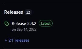
If you go to the sammy-c21 documentation. The dev branch is linked and as far as I can see it ends with 3.4.2.
Maybe i'm too stupid to use github. -
RE: Question about Sammy-C21 boardposted in Firmware developers
@fcwilt
It means that the effort is quite high.
It's a poor performance that the latest firmware is no longer provided.
Until now I thought the Sammy-C21 is a cool option, but not any more.... -
RE: Question about Sammy-C21 boardposted in Firmware developers
@fcwilt
To me it sounds like you have to buy a cow to get a liter of milk. -
RE: diagonal line on print causing layer shifting?posted in Tuning and tweaking
@53581
Bang-bang control on the bed could cause kind of stripes.
As far as i can see, your config. may have been created for an older firmware. The heater parameters have changed with 3.4.
I don't know if that really makes a difference.
But I would change to PWM-control and autotune the bed heater and the tool.
Please also post the content of config-override.g as the parameters should be stored there..... -
RE: Why MQTT only available for WiFi boards?posted in General Discussion
@T3P3Tony
Can you please provide an update on this? -
RE: Layer count way offposted in Duet Web Control
@DaveA
Maybe set the custom end G-code as described here
https://forum.duet3d.com/post/314534 -
RE: Issue with secondary extruder drive on CAN bus with Mini5plusposted in Duet Hardware and wiring
@droftarts
For push-pull M567 also is missing.... -
RE: Bltouch not deploy sometines it doesposted in General Discussion
@Tinchus
I would suggest the following additions or changes:
In config.g; ENDSTOPS M574 X1 S1 P"!io8.in" M574 Y1 S1 P"!io6.in" M574 Z1 S2 ; configure Z-probe endstop for low end on Z ; bltouch M950 S0 C"io7.out" ;change S2 to S0 M558 P9 C"io7.in" H5 F100 T3000 R0.2 G31 X-7 Y37 Z3.73 P25 ; bltouch offsets M557 X7:193 Y18:195 S26.5:29.5 ; define mesh gridIn deployprobe.g
M280 P0 S10 ;change P2 to P0In retractprobe.g
M280 P0 S90 ;change P2 to P0 -
RE: Common GND on Duet2 Wifi?posted in Duet Hardware and wiring
@TomasL
Depending on what is needed, the positive voltages can be used together.
But then also pay attention to the cable cross-section -
RE: Bltouch not deploy sometines it doesposted in General Discussion
@Tinchus
Sounds plausible to me, BL-Touch does not like magnetic fields. -
RE: Bltouch not deploy sometines it doesposted in General Discussion
@Tinchus said in Bltouch not deploy sometines it does:
I had exactly the same issue, that was driving me crazy....
check the pin
"Try loosening or tightening the set screw slightly to adjust the trigger sensitivity."
The description how to set up the srew is in the manual
In the end a quarter turn had reliably solved the problem. -
RE: Endstops after coreXY conversion configuration tool v3.5.4posted in Duet Hardware and wiring
I have noticed that the limits of the old and new files are different. In addition, the old homing script uses hard-coded limits and the new variables dependent on config.g.
So first check the correct values and adjust them for M208 in config.g -
RE: How hard is setting up CAN connected boards?posted in General Discussion
@droftarts said in How hard is setting up CAN connected boards?:
Click on the "Connecting WITHOUT Duet 3 Tool Distribution Board" tab.
Oh yes, the tabs....I sometimes overlook them. I'm probably not the only one....