Navigation

    Duet3D Logo

    Duet3D

    • Register
    • Login
    • Search
    • Categories
    • Tags
    • Documentation
    • Order
    1. Home
    2. Phaedrux
    3. Best
    • Profile
    • Following
    • Followers
    • Topics
    • Posts
    • Best
    • Groups

    Best posts made by Phaedrux

    • Tuning Macros Menus (Accel, Jerk, Retraction, Pressure Advance)

      0_1532570209712_Screenshot 2018-07-25 19.26.32.png

      A couple weeks ago I posted a firmware retraction tuning macro set. And now I've taken it to the logical conclusion and included macros for live tuning many more variables. This makes finding the sweet spot for print speeds quick and easy. Simply print your favourite tuning STL and start making adjustments to see the effects in real time.

      • Acceleration for X, Y, Z, E, axis plus Print and Travel moves
      • Jerk for X, Y, Z, E
      • Pressure Advance with values for Bowden and Direct drive
      • Firmware retraction variables

      You can download the macros from github here in a zip file.

      The easiest way to install them is to put the SD card into your computer and extract the zip file into the /macros folder.

      The menus work best with a PanelDue, but work with the DWC macros menu as well.

      Values have been stepped in increments of 60mm/min (1mm/s) for most things. But steps of 1000 are also available. Z axis adjustments are more sensitive at 10mm/min increments. I've tried to go to ranges high enough that should be good for most users.

      For acceleration and jerk tuning to work, make sure you've disabled any accel or jerk control inserted by the slicer.

      For retraction tuning you must be using firmware retraction. See the other firmware retraction thread for more details.

      Each time a value is changed it is echoed to the console window so you can see what the last used value was so you can add it to the config.g to make it permanent. You may need to turn on command echo in the DWC settings for pop ups to show up. In the PanelDue they show up in the console window.

      I've done my best to make sure all the commands are accurate to what they say they are, but mistakes may have been made. I've done some testing, but I haven't tested every single one. Even if I have made no mistakes, you can still potentially damage something by choosing a value that is completely unreasonable for your setup. For example, choosing a very long retraction value for a direct drive extruder. I recommend you start with small values and work your way up.

      If you find any mistakes, please let me know and I'll update the download link.

      If you change things too much and want to go back, you can simply reboot the controller and the defaults from config.g will be loaded. Alternatively, you can edit the Return to Defaults macro to use your current values before you start to test, that way you can return to your old values with the touch of a button.

      Here's a few more pictures of what the menus look like in the DWC:

      0_1532572721686_Screenshot 2018-07-25 19.26.52.png

      0_1532572739163_Screenshot 2018-07-25 19.26.57.png

      0_1532572788665_Screenshot 2018-07-25 19.27.03.png

      0_1532572749747_Screenshot 2018-07-25 19.27.07.png

      0_1532572767965_Screenshot 2018-07-25 19.29.27.png

      0_1532572800675_Screenshot 2018-07-25 19.29.31.png

      More photos showing the menus on a PanelDue 7.

      IMG_8931.JPG
      IMG_0073 copy.jpeg IMG_0072 copy.jpeg IMG_0071 copy.jpeg IMG_0070 copy.jpeg

      posted in Tuning and tweaking
      Phaedrux
      Phaedrux
    • Community Projects Wiki

      I've started a wiki page to list all of the active community hardware and software projects. There are so many useful addons it would be nice to have a centralized place to gather them together.

      I've added a few to start with that I could remember off the top of my head, but I know there are a ton of others out there, so please post a link to any you'd like added.

      https://duet3d.dozuki.com/c/Community_Projects

      posted in General Discussion
      Phaedrux
      Phaedrux
    • Danal's passing

      It's been brought to my attention that one of our most active and valued community members has passed away. If you've ever read one of Danal's helpful and informative posts you'll likely be as disheartened as I was to learn that he has passed.

      https://www.dignitymemorial.com/obituaries/frisco-tx/danal-estes-9198882

      posted in Off Topic
      Phaedrux
      Phaedrux
    • My custom D-Bot

      Over the past year I've been planning, building, and commissioning a custom D-Bot CoreXY I call the Z-Bot. I chose the D-Bot because it seemed fairly sturdy, was expandable to the size I wanted, and there seemed to be a decently sized community surrounding it. There's still a few things I'd like to do with it, but for the most part I consider it finished.

      ZBot

      Details:

      • 300mm^3 D-Bot hardware kit from AliExpress
      • 300x275x300 print volume
      • DuetWifi with 7" PanelDue
      • MeanWell SE-200-24V passively cooled PSU
      • 13"x13"x1/4" MIC-6 aluminum build plate bonded to 12"x12" PEI
      • 600w AC Silicone heater with Fotek SSR-40DA relay
      • 0.9 steppers for A and B motors from SteppersOnline
      • 1.8 stepper for the Z Axis
      • Three TR8*1mm lead screws connected with 1524mm GT2 continuous loop belt
      • Titan Aero extruder on custom carriage with BLTouch, belt tensioners and C shaped cooling shroud.
      • E3D pancake motor for extruder
      • Gates GT2 belts
      • Delrin V-Wheels
      • Aluminum spacers and precision shims.
      • Hardened steel 0.4 or 0.6 nozzle, 40w heater, PT100 sensor
      • Suited for high temp plastics
      • Sunon blower and Noctua fans for quiet printing
      • Z Max optical endstop for power failure recovery
      • PSU has integrated USB power ports and voltage display
      • Buck converter provides 12v for the fans
      • Raspberry Pi Zero W with camera module running MotionEye, powered by PSU USB ports.
      • Proper grounding throughout with a Ground Fault Circuit Interrupter plug
      • Aluminum plates and brackets in place of plastic where ever possible
      • Plastic parts printed in AMZ3D Red PLA and SpoolWorks Red PETG
      • Prints comfortably at 133mm/s with moderate acceleration and jerk settings.
      • Travel moved at 233mm/s 3000mm/min acceleration.

      Here's a list of the key mods I used on this printer:

      • 3rd Z-axis Belt Tensioner for DBot
      • Two-bearing Z mount for 3 lead screw for DBot
      • 2x1 plate with cutout
      • 3-wheeled Y guide
      • 3-wheeled Z guide
      • DuetWifi box for 2020
      • 7" PanelDue case for V Slot
      • MeanWell SE-200-24 PSU Case for VSlot
      • AC-Bot 2.0.2 Titan Aero X Carriage for DBot

      ZBot

      The Z axis took the most time to finalize. The DBot's biggest weakness in the stock build is the bed. The stock build is only for 300x200 and uses a cantilevered bed supported at the back on V wheels and requires you to find the center of gravity for the bed assembly to position the lead screws. On a 300x300 build the amount of droop and bounce is unworkable. Furthermore, the stock build uses 2 Z motors which are problematic to keep in sync.

      My solution was to add another beam and wheel assembly to the front so that it rides on all 4 corners. Then to balance the weight between 3 lead screws, one at the middle back, and two at the front left and right. This makes for a very solid bed that rides smoothly up and down the vslot.

      ZBot

      To keep the 3 screws in sync I used a single motor and a 1524mm continuous loop GT2 belt. Each screw is supported in it's own double bearing block. The motor mount also doubles as a slide tensioner for the belt. Both are existing mods from the community.

      ZBot

      In order to reduce the torque requirements for the single motor, and to prevent the likelihood of the heavy bed auto rotating downwards when power is removed, I chose 1mm lead screws and a 1.8 motor and a 2:1 gear ratio between motor and screws. (20T drive pulley, 40T screw pulley) It also allows for 0.0025 mm layer step intervals for high Z resolution.

      ZBot

      Originally I worried that the Z axis would be very slow in this arrangement, but it's actually turned out to be very stable, and quite fast. My only disappointment in the build is the aluminum plate has a slight bulge on one corner, likely from shipping damage. Mesh bed compensation to the rescue.

      Where possible I switched to 3 wheel carriage mods with tensioners to help make getting the wheels aligned and equally tensioned a lot easier.

      With the Titan Aero and a 40w heating cartridge I've managed PLA print speeds up to 200mm/s (0.4 width, 0.2 layers, 215c) on infill and perimeters with good quality. Overall I'm very pleased with the quality and speed of the printer, thanks in no small part to the Duet. The power and flexibility of RepRapFirmware cannot be understated. Being able to create and customize macros and live adjust values is a game changer. I can never go back to the way it once was.

      Here are some example prints.

      lawn darts
      lawn darts

      Lawn Darts printed at 0.3 layer height @ 100mm/s

      benchy

      boaty

      alt text

      For anyone building a DBot and wanting to see my configs, you can find them here: DBot Config Files

      More photos of the printer and example prints can be found here: Photo Album

      Thanks for taking a look.

      posted in My Duet controlled machine
      Phaedrux
      Phaedrux
    • Firmware Retraction Tuning with Macros

      You can find a more complete set of tuning macros here:

      https://forum.duet3d.com/topic/6181/tuning-macros-menus-accel-jerk-retraction-pressure-advance


      Retraction Tuning Macros

      I took some time today to whip up a set of macros that should make fine tuning your retraction settings much easier.

      They can be found here: DropBox Download for Retraction Tuning Zip file

      0_1531091983047_Screenshot 2018-07-08 17.18.04.png

      Here's how it works.

        1. First you must have firmware retraction enabled in your slicer.
          1a. In Slic3r PE, this can be found under Printer settings, General tab, Firmware retraction check box near the bottom of the right pane.
          1b. In Cura, you will need to use version 3.4+ and install the Printer Settings plugin from the tool box, and then unhide the firmware retraction setting for it to show up in the right menu bar. It'll show up under the Printer Settings menu at the bottom.
          1c. In Simplify3D you'll have to setup a post processing script to insert the G10/G11 retraction commands at the appropriate place https://thrinter.com/using-firmware-retraction-with-simplify3d/
        1. Download a retraction tuning model from Thingiverse.
          There are plenty of guides out there that give you an idea of what to start with.
        1. Slice the model with firmware retraction enabled and your usual print settings
        1. Use the macros provided to quickly step through the various parameters while the print is running and note how they affect stringing and layer seams.
          4b. There are a range of hopefully sensible values for both direct drive, and bowden tube setups.
          4c. Every time you choose a value the current settings are echoed back so you can find them in the console.
          4d. Warning Be careful with retraction distance. Using Bowden distances in a direct drive system will quickly pull your filament right out and possibly lead to a jam.
        1. Once you have things looking good, use the macro to report the current settings and enter it into your config.g to make them permanent.
        1. You can edit the "Return to defaults" macro with your usual retraction settings so you have something to quickly return to if you really mess it up.

      Let me know how it works out for you if you try it or if you find any errors. Speeds and distances are fairly granular but you might want to fine tune by hand further once you get into the ball park.

      In addition to retraction parameters there is also extruder acceleration, jerk and travel acceleration which you can tune. These can be particularly useful for eliminating blobbing and stringing.

      posted in Tuning and tweaking
      Phaedrux
      Phaedrux
    • RE: Tuning Jerk/Accel/Speed settings

      Assuming you have basic calibration out of the way...

      The volumetric extrusion rate of your hotend will be the limiting factor. Once you know that you can find a print speed/layer height/extrusion width combo that maximizes the extrusion rate and produces a good surface finish.

      I think this is too often overlooked in 3D printing. When I see people say they are printing at 200mm/s I have to wonder what layer height and extrusion width are they using? What is their acceleration and jerk values? Is the surface quality any good? Is the part strong?

      Take this for example:
      ecf5100a-2603-4fe2-85af-ed0cf2e3707b-image.png

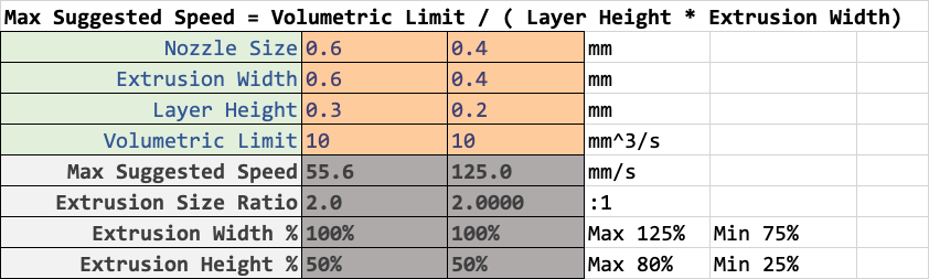
      One is printing at 55mm/s and the other at 125mm/s. But the volumetric rate is the same, and if you sliced the same model with those two different profiles for layer height and extrusion width, total print time will be roughly the same. (slightly less for the 0.3 layer profile due to less repetition of movement).

      Depending on what you're printing, one or the other may make more sense, but the point is that print speed is almost irrelevant as long as you are maximizing your volumetric rate, you will be completing the print in as little time as possible.

      In addition to the melt rate limit, you'll have to be able to cool the extruded plastic fast enough. So your cooling solution needs to be sufficient, and minimum layer time will be practical limit on speed at the other end.

      You can use some calculators to find the theoretical limits for top speed and acceleration, but by the sounds of it they are already well above practical values for qualities sake on your printer.

      Now you don't mention much about your printers mechanical setup, but your sig says Hephaestus, which would be quite rigid. But as a general rule I would suggest that you set your maximum X Y speed to be equal to your travel move speed. That way when you use the speed factor slider you won't be able to increase your travel speeds to dangerous levels.

      For travel acceleration, using the acceleration calculator to find the max for your motors/power supply without losing torque would be a start. In practice, you'd probably find the travel moves to be particularly violent, and this can have a negative impact on quality from ringing, and from the nozzle dragging filament at the end of an extrusion move causing stringing or blobs.

      To find this speed/accel combo for travel moves, I would do a dry run of a larger model to get a feel for what travel moves would actually look like. Adjust the speed factor and travel acceleration during the print. You'll be able to tell the difference between sluggish movement and rough jerky movement. (for my coreXY travel is 175mm/s and 2500 accel and 1500mm/min jerk. Anything more is too rough and may skip steps if it catches a curled edge.)

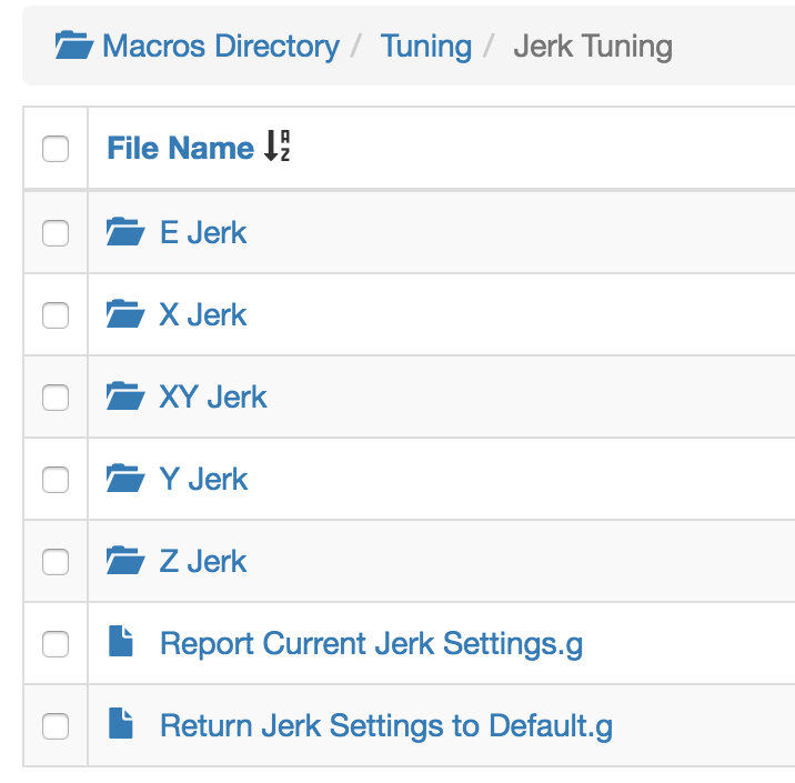
      Once you have travels set up, you can move onto print moves. For external perimeters, I use the max speed that maximizes my volumetric flow, and then limit that for quality using acceleration and jerk. First I tune for jerk by setting acceleration to the same as the travel acceleration and then adjusting jerk until it sounds smooth. I know that's subjective, but trust me, you can tell the difference between smooth motion, sluggish motion, and smooth but rapid motion. (For me that's 1200mm/min for external walls, and 1500mm/min for infill)

      Now that print speed and jerk is set. You can use a test cube for ringing testing to dial in wall acceleration. Just start low and increase it every few layers and repeat until you've got no ringing. Something like this scaled up to 100mm cubed works well. ringtest.stl

      You may also find dynamic acceleration adjustment useful.

      For internal features acceleration is less critical because ringing doesn't really matter, so I usually use a value in between the external wall and travel values.

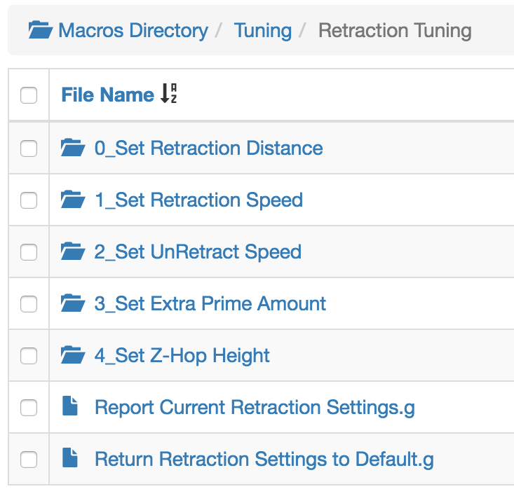
      At that point I tune for retraction distance and speed using a simple retraction tower. Using firmware retraction allows you to change the values every few layers. Within about two cycles you can get it dialed in pretty well. For me, 1mm retraction and 60mm/s retract and 45mm/s unretract seems to work best (titan aero)

      With retraction done pressure advance is next. I use the simple cube/cylinder method described here: https://duet3d.dozuki.com/Wiki/Pressure_advance#Section_Methods_of_finding_the_right_amount_of_pressure_advance

      Make sure your extruder max speed/accel/jerk values are sufficiently high to allow pressure advance to work optimally.

      Once you find the right PA value, you may need to reduce retraction distance slightly and increase the skin/infill wall overlap.

      I should also mention that I usually use Cura because it allows for detailed control over speed/accel/jerk values per move type. This gives me a great deal of control, but it also means that those values are baked into the gcode and cannot be changed on the fly during a print. Disable those features during live tuning obviously.

      Prusa slicer allows control over speed and acceleration for some moves but not jerk.

      If you use a slicer that doesn't give you that level of control, you can at least use M204 to set separate acceleration values for print and travel moves.

      posted in Tuning and tweaking
      Phaedrux
      Phaedrux
    • Preview version of CNC optimized DWC.

      There is a preview of the CNC version of DWC at https://github.com/Duet3D/DWC-CNC/releases.

      You may also be interested in some plugins created by @Sindarius

      https://github.com/Sindarius/DWC_GamepadJogger_Plugin
      Adds the ability to use a gamepad to jog your spindle

      and

      https://github.com/Sindarius/DWC_GCodeViewer_Plugin
      Will let you get a visual of your gcode, I recommend sticking to wire mode for CNC gcode. Just recently finished adding G2&3 support.

      posted in CNC
      Phaedrux
      Phaedrux
    • Ender 3 Pro and Duet Maestro Guide

      I've been working on a 4 part step by step guide to upgrading an Ender 3 Pro with the Duet 2 Maestro board, covering wiring, generating a config file set, commissioning the hardware, and doing some basic calibration to get started with good prints.

      Hopefully this will be helpful to anyone doing a similar upgrade. Even if it's a different printer than the Ender 3, it's generally applicable to adapting any printer to use a Duet.

      Future guides will go over adding a BLTouch, replacing 24v fans with 12v fans, adding LED strip, using mesh bed compensation, adding a PanelDue, etc. So stay tuned for that.

      Thanks to everyone who's already provided feedback.

      Check it out here:

      Ender 3 Pro and Duet Maestro Guide Part 1: Wiring
      Ender 3 Pro and Duet Maestro Guide Part 2: Configuration
      Ender 3 Pro and Duet Maestro Guide Part 3: Commissioning
      Ender 3 Pro and Duet Maestro Guide Part 4: Calibration
      Ender 3 Pro and Duet Maestro Guide Part 5: Upgrades

      Config file examples available here: https://github.com/x0rtrunks/Ender3DuetMaestroConfigs

      posted in Example setups and prints
      Phaedrux
      Phaedrux
    • RE: Why I went back to RRF2

      @jens55 said in Why I went back to RRF2:

      Moderators .... could we please lock this thread and stop with the negativity please ?

      Yikes. Consider it locked! I take a day to do some yard work and y'all turn to hooliganism!

      posted in Example setups and prints
      Phaedrux
      Phaedrux
    • Turn your printer into a Juke Box.

      If you happen to have a PanelDue, you can use the internal buzzer to play tones with the M300 command. In the past I've used this feature to compose some little tunes to play when starting or ending a print, and occasionally I've converted some arduino piezo buzzer code to play some more complicated songs. But now there is a tool available (not mine) that will convert a complete midi song into gcode commands, which allows for some rather impressive music playback.

      Tool here: https://alexyu132.github.io/midi-m300/

      GitHub here: https://github.com/alexyu132/midi-m300

      Video example here: https://www.reddit.com/r/3Dprinting/comments/g3lqm2/i_wrote_a_program_that_converts_midi_files_to/

      Example Gcode output if you want to test it out: TetrisA.g

      Simply download any midi song you want from the internet. It generally works best with single instrument midi files, but even multi instrumental tracks work surprisingly well. Upload it to the tool, choose which instruments to include (might need to experiment), check the box for Duet support which adds G4 commands after each tone to give it time to play, and then generate the gcode. You can preview it right there, and if it's to your liking, copy and paste the gcode into a text file, save it with a filename and .g extension, and upload it to the macros folder of the Duet. Run the macro to enjoy.

      (Note: If you don't have a PanelDue connected, it will still play the tones through the DWC if you're connected. I haven't tested it with the 12864 display connected to a Maestro, but it may also work.)

      posted in 3D Printing General Chat
      Phaedrux
      Phaedrux
    • RE: Where to start with a comprehensive extrusion calibration?

      This is a pretty comprehensive topic and as you've already seen can get pretty complicated. But here's what I've gathered together from research and experience. I've been trying to work this up into a wiki article for the documentation, so here's a rough version of it. Maybe if people give some feedback and their own experience and observations I can incorporate that as well into the final article.

      1. Measure your filament diameter using a caliper. Several places over a few meters worth and in at least 2 orientations (in case it's oval and they all are). Use the average value as your filament diameter in your slicer.

      2. Figure out the correct e steps per mm for your extruder. The manufacturer probably already gave you a recommended starting point based on the mathematics of the extruder configuration.

      e_steps_per_mm = (motor_steps_per_rev * driver_microstep) * (big_gear_teeth / small_gear_teeth) / (hob_effective_diameter * pi)

      Then to get a closer true value you can actually extrude some filament and compare the commanded extrusion to the actual extrusion. You can do this with or without a hotend installed, but if you have the hotend and nozzle installed you should use a slow extrusion speed and high temp to remove any back pressure from skewing your results.

      I use this macro, which should be fairly self explanatory.

      ; 0:/macros/Calibration/E Steps Calibration.g
      ; Macro to calibrate the extruder steps per mm by extruding 110mm of filament slowly and comparing expected result with actual result.
      
      M291 S3 R"Proceed?" P"Run E Steps per MM Calibration?"
      M117 "Homing"
      G28 ; Home All Axis
      M98 P"0:/macros/1_Nozzle Access.g"	; Move print head to nozzle access
      T0	; Activate Tool0
      G10 P0 S220 R0	; Hot end to 220c
      M291 S3 R"Heating to 220" P"Mark 110mm on filament from top of extruder body."
      M116	; Wait for temp to 220
      M291 R"Temp reached." P"Extruding 100mm at 1mm/s"
      M83 ; relative extrusion
      G1 E100 F60	; Extrude 100mm of filament at 1mm/s
      M400	; wait for moves to complete
      G10 P0 S0 R0	; Turn off hot end
      T0	; Deactivate Tool0
      M291 S2 P"Measure distance to mark and update e steps."
      M291 S2 P"old_e_steps * (100 / (110 - distance_to_mark))"
      M291 S2 P"Repeat test to verify." R"E Steps calibration complete."
      

      The gist of it is mark 110mm from the where the filament enters the extruder on the filament. Extrude 100mm slowly. Measure the distance from the extruder to the mark. It should be 10mm. Use this formula to determine your new esteps value. New esteps = old_e_steps * (100 / (110 - distance_to_mark))

      Do this a few times until the values start to converge around a value. Your measuring isn't likely to be perfect every time, so the best you can do is get it narrowed down. You'll do further fine tuning of the slicer extrusion multiplier next.

      1. Further refine your slicer extrusion multiplier/flow rate.

      Print a 50mm solid cube in vase mode. Set the external perimeter extrusion width to match your nozzle diameter. Set the flow % or extrusion multiplier or whatever your slicer calls it to 100% or 1, or whatever a full value is. Print using the lower temp range of your filament at a reasonable speed and make sure you have adequate cooling. When it's done printing and it looks like it printed consistently (as in no overheating artifacts or other oddness) measure the wall thickness with your calipers. Try to just pinch the top 1mm or so. Measure all four walls and take the average. Now compare the measured result to the commanded extrusion width and use the formula New Extrusion multiplier = Old Extrusion Multiplier * (Expected Thickness/Measured Thickness)

      You may need to repeat this test a few times to dial it in as well.

      Once you've got the multiplier where the extrusion width is measured correctly you should do some actual prints now and watch how it looks. Does the solid infill look smooth and solid or is there a gap between lines, or does it pile up and look rough? Is there a gap between perimeter walls? Adjust the extrusion factor on the fly by a few percent and watch the changes. You'll know it's right when it looks right. Even with everything calibrated I'll still watch the first few layers and adjust as needed on the fly. If you use a lot of different materials this can be a quicker way of getting a good extrusion multiplier than doing a full set of calibration prints. Your eyeball is better at detecting a bad looking print better than a caliper.

      1. Make sure your first layer is dialed in.

      Over extrusion on the first layer can impact the following layers and make it seem like you're over extruding when you actually aren't. If your flow is dialed in, and your z height is accurate the first layer should print well using normal flow and normal extrusion width, you shouldn't need any tricks or hacks of over extrusion to get a good first layer to stick. Z=0 should be 0 and z=0.2 should be 0.2.

      1. Pressure advance.

      Tuning pressure advance can get as complicated as you want it to get. If you have a direct extruder it's going to be a lot easier than if you have a really long bowden tube setup. For direct drive start with 0.05 and see how a print actually looks. If you notice blobs or bulging corners you can increase it a bit. Increasing jerk can also help with getting sharper corners. It's a bit of a fudge factor value and it's going to be very hard to do one test and say that's a perfect value for it. It will depend on many factors like material type, print speed, print temp, layer height, etc. As a rule of thumb, some is better than none, and you'll know when it's too much because it will look like under extrusion on direction changes.

      1. Speed, acceleration, jerk

      This is going to depend a lot on your mechanics and printer type. Generally I would say start low and work your way up until things sound bad and back it off. Ask around for profiles from people who have a similar printer to you. It may help to keep in mind that a 3D printer is a pressure based extrusion system first and foremost. So your goals in tuning should be to try and maintain a smooth flow of extrusion throughout the print. Rapid fluctuations in flow rate aren't ideal. That means going too fast and going too slow are bad, and it's even worse to alternate from too fast to too slow and back again.

      1. Max flow rates

      To find your max print speed you'll need to know your max extrusion rate. Your melt rate will be your hard limit on speed. This is a good place to mention that you should have completed a PID tune on your hotend before doing this since the heater will be need to keep up with a maximum flow of plastic and fluctuating temps could lead to weird extrusion problems and limit your max flow rate.

      You can find your max feed rate by getting your hotend up to print temp and extruding starting at a low speed and increasing it until your extruder starts to skip steps. Once you have your max feed rate without skipping you can use

      Max Flowrate = Max Input Feedrate * pi * (Filament Diameter/2)^2

      That will give you a volumetric limit. So say you can extrude at 6mm/s and your filament is 1.715mm that gives you 13.86 mm^3/s^2 So that's how much plastic you can extrude reliably. Asking for more will give you under extrusion. This is where non-linear extrusion can start to come into play to helkp even out the high end of the rate range, but honestly it's not necessary to get good prints provided you're printing at reasonable speeds. If you want to push the envelope there is the main thread on non-linear extrusion and how you can try to calibrate it. But honestly, if you really need to push a lot of plastic, get a larger capacity hotend like a volcano.

      Then you can use that limit to find your top speed based on the layer height and extrusion width you want to use. Max Suggested Speed = Volumetric Limit / ( Layer Height * Extrusion Width) So if we say the limit is 13, layer height 0.3, extrusion width 0.6, we get 72mm/s as a top speed that our hotend could reliably deliver enough plastic for.

      I'm gonna stop there.

      If you're interested, here's a link to the excel spread sheet I use to keep track of all this stuff. It'll make the formulas easy to use anyway.

      https://www.dropbox.com/s/ebkvpqseyts305r/3DPrintCalculators.xlsx?dl=0

      posted in Tuning and tweaking
      Phaedrux
      Phaedrux
    • Ender 3 Pro and Duet 3 Mini 5+ Guide

      A draft release of the Ender 3 Pro and Duet 3 Mini 5+ upgrade guide is now available for your perusal. Hopefully you find it helpful as the Mini 5+ starts to arrive at your doors. If you find any problems or have any questions, please let me know in this thread. Further guides on configuration etc are on the way.

      https://duet3d.dozuki.com/Guide/Ender+3+Pro+and+Duet+3+Mini+5++Guide+Part+1:+Wiring/87

      https://duet3d.dozuki.com/Guide/Ender+3+Pro+and+Duet+Mini+5++Guide+Part+2:+Configuration/88

      posted in Duet Hardware and wiring
      Phaedrux
      Phaedrux
    • RE: Duet 3 demo at TCT

      @deckingman

      Currently the DWC runs on the same CPU on the Duet that also handles everything else the printer has to control. It used to run on the even slower wifi chip. And while the Duet is far faster than the old school 8bit controllers like the Arduino, it's still nothing compared to even a $5USD Raspberry Pi Zero W single board computer.

      Arduino 2560 = 16Mhz 8bit ATmega2560 with 256Kb ram
      Duet 2 = 120MHz 32bit ARM Cortex-M4 with 128Kb ram and 512kb flash
      Duet 3 = 300Mhz ARM??
      Raspberry Pi Zero W = 1Ghz with 512Mb ram
      Raspberry Pi 3B+ = 1.4 Ghz 64bit quad core ARM Cortex-A53 with 1Gb ram

      The Duet electronics are freed up to function exclusively as the realtime hardware controller, possibly raising the ceiling on step rates. The single board computer like the Raspberry Pi can run a full modern Linux operating system which opens the door to much richer web application features than even the current DWC can provide. The easiest comparison is Octoprint. It has the same basic functions as the DWC, but is extensible with plugins to allow all sorts of other features and integrations.

      Here's a few examples of some possible improved functionality this could open up.

      • Gcode realtime preview and time simulation estimates in a fraction of the time.
      • statistics tracking of successful prints and how long they took
      • database support to allow tracking and display of metadata for gcode files
      • thumbnail renders of the actual model in addition to the name
      • push notifications to a mobile device using various messaging services to let you know if a print completes or halts
      • USB webcam support and easy time lapses
      • local slicing of STLs to eliminate the need for a seperate PC
      • detailed logging and graphing of real time data
      • automatic firmware updates or package management
      • whatever else plugin developers can come up with

      https://octoprint.org/ for more information. They offer a prebuilt sd card image that you put on a card and boot the Pi with and you're off to the races. It's geared towards the average user to to able to get up and running easily, but I could see how such a platform would be attractive to OEMs as well since they could customize the experience and extend functionality themselves to differentiate their offering from competitors.

      Now I'm not knocking the DWC in the least. It does exactly what it needs to do and does it very well. But it is limited by the hardware it has to run on. A Pi3 is about $20 USD. So quite affordable and allows for a whole other level of capabilities.

      I should clarify that I'm not hoping for a replacement of the DWC with octoprint. Rather I'm excited to see what can be done to expand the capabilities of the DWC given improved hardware. Though I could see a way in which octoprint could be customized to become a duet branded version to look and function much like the DWC does now with the added option of plugins. Pure speculation on my part.

      posted in General Discussion
      Phaedrux
      Phaedrux
    • RE: Another reason why not to by a clone (of anything)

      English, though tough, can be understood through thorough thought.

      posted in Off Topic
      Phaedrux
      Phaedrux
    • RE: Gradually reduce grid compensation when printing

      @Ted @Edgars-Batna I've updated the mesh compensation wiki article to include more information on using taper and put a note about it under the G29 entry.

      posted in Firmware wishlist
      Phaedrux
      Phaedrux
    • RE: Do yourself a favor,use the tuning macros,top of this page

      Glad you found them useful.

      posted in Tuning and tweaking
      Phaedrux
      Phaedrux
    • RE: Cancelling a print "un-homes" axes

      @gnydick said in Cancelling a print "un-homes" axes:

      @Phaedrux honestly, it's nothing to do with my scripts. I've printed thousands of prints that I've cancelled because I'm tweaking and tuning quality for intricate functional prints. It happens randomly, less than .1% of the time. Please just take it as face value that it's a bug. Though it has happened twice in the last 3 days, which is odd.

      Great. Thanks for the single data point with no context. We'll just have to wait until it affects someone else so we can see the relevant files.

      posted in General Discussion
      Phaedrux
      Phaedrux
    • RE: Limit axe problem.

      @Clement-B said in Limit axe problem.:

      M208 X0 Y0 Z0 S0 ; Limit min axe=S0 X-> 279.4mm= 11" Y-> 346.075mm= 13 5/8" Z-> 136.525mm= 5 3/8"
      M208 X279.4 Y346.075 Z136.525 S1 ; Limit max axe=S1 13.625" 5.375"

      I think you have those reversed.

      https://duet3d.dozuki.com/Wiki/Gcode#Section_M208_Set_axis_max_travel

      Snnn 0 = set axis maximum (default), 1 = set axis minimum

      posted in CNC
      Phaedrux
      Phaedrux
    • RE: 6th-order jerk-controlled motion planning

      Lots of good reading here for the technically inclined.
      https://github.com/KevinOConnor/klipper/issues/57

      I think we need to keep from getting derailed by the talk of replacing sharp corners with arcs. That's not really what S-curve acceleration is about. Smoother accel and decel, less vibration, open the door to higher speeds with similar quality. Who doesn't want shorter print times and a quieter printer?

      Now that we have 32bit cpus we have the opportunity to spend more cycles on potentially better path planning. It's something worth investigating, because the potential is certainly there. Real world tests can only come after there is an implementation available to test against.

      posted in Firmware wishlist
      Phaedrux
      Phaedrux
    • RE: Firmware Retraction Tuning with Macros

      I've updated the download link to include macros for tuning extruder acceleration, jerk, and travel acceleration.

      Next up, macros for tuning XYZ acceleration and jerk.

      posted in Tuning and tweaking
      Phaedrux
      Phaedrux
    • RE: DuetWifi clones and support

      It's a bit of a insult to injury situation though. If you have to expend extra effort to block people from seeking support not only did you not make the sale, now you have to spend to keep them out.

      The hardware is open source, so as long as the license is adhered to, other boards can be made, however that explicitly comes with no support or warranty from Duet.

      Now is it worth it to ignore people that bought a clone and come here for support? Some people weren't aware they were buying a clone maybe. Or maybe they've bought a clone and liked it and bought the real thing.

      I think if you turn these people away entirely you'll lose them as a customer for ever. Whereas if you show them the kind of support you get from buying this product hopefully they will appreciate it and buy a legitimate product from a reseller in the future.

      posted in General Discussion
      Phaedrux
      Phaedrux
    • Any one print a Christmas gift this year?

      3D46E4B4-DE71-4D95-AAD5-7B8414676783.jpeg

      This year I printed some small detail sanding blocks for my dad since he does a lot of wood working. I designed a small box to fit them all as well.

      Have you made any gifts for people this year?

      posted in 3D Printing General Chat
      Phaedrux
      Phaedrux
    • RE: start.g -> end.g?

      @alankilian said in start.g -> end.g?:

      so I don't know if you would need to make sure that got added in the slicer or not.

      Yes you would need M0 at the end of the print file to execute stop.g

      I'll move this to the wishlist since having an end.g that behaved similar to start.g without requiring a call would be a useful addition.

      posted in Firmware wishlist
      Phaedrux
      Phaedrux
    • RE: Z homing Gcode bloody for beginners

      @ted Yes I think you should be able to do that.

      https://duet3d.dozuki.com/Wiki/Gcode#Section_G0_G1_Move

      1RepRapFirmware can be set to enable or disable the "sensing" of endstops during a move. Using the S1 or S2 parameter on a delta printer causes the XYZ parameters to refer to the individual tower motor positions instead of the head position, and to enable endstop detection as well if the parameter is S1.

      If S3 is passed instead, RepRapFirmware will measure the axis length.

      For example:

      ; Homeall.g
      
      G91 ; relative mode
      G1 S2 Z4 F200 ; raise head 4mm for clearance
      G1 S1 X-340 Y-340 F3000 ; move up to 340mm in the -X and -Y directions until the homing switches are triggered
      G1 S2 X4 Y4 F600; move slowly 6mm in +X and +Y directions
      G1 S1 X-10 Y-10 ; move up to 10mm in the -X and -Y directions until the homing switches are triggered again
      G90 ; back to absolute mode
      G1 X100 Y100 F2000 ; put head over the centre of the bed, or wherever you want to probe
      G30 ; lower head, stop when probe triggered and set Z to trigger height
      G1 S3 Z+400 ; Seek Z max endstop and when endstop triggers set axis length.
      

      The G1 S3 Z+400 move at the end would travel to the top of the Z axis and set the M208 to be the resulting distance. This is possible because your zprobe has identified Z0 for you already. In fact, you could use the above gcode to home even without an actual z probe like a BLTouch. You set the probe type to be manual, and it will pop up a jog dialogue asking you to move the nozzle to touch the bed.

      In config.g it would need M558 P0 to set manual probe type and G31 X0 Y0 Z0 to set the nozzle to probe offset as 0 since the nozzle is the probe.

      Another way to set the Z Max axis is to have a macro that will home to z0 and then move up 300mm and then you use an adjustable set screw or optical flag to trigger the endstop at exactly 300mm. That way, as long as your bed is pretty stable in where Z0 is, it will stay accurate for quite some time. So need to measure it on every homeall, saving quite a bit of homing time.

      Something like this: 0_1556310613251_2_HomeZMax.g 0_1556310657894_0_Measure Zmax trigger.g

      posted in Tuning and tweaking
      Phaedrux
      Phaedrux
    • RE: macros in sys and in macros ?

      I've always been in the habit of using the full absolute path for all macro calls including the SD card drive letter. That also helps me keep track of where that macro is living if I need to look it up later.

      posted in General Discussion
      Phaedrux
      Phaedrux