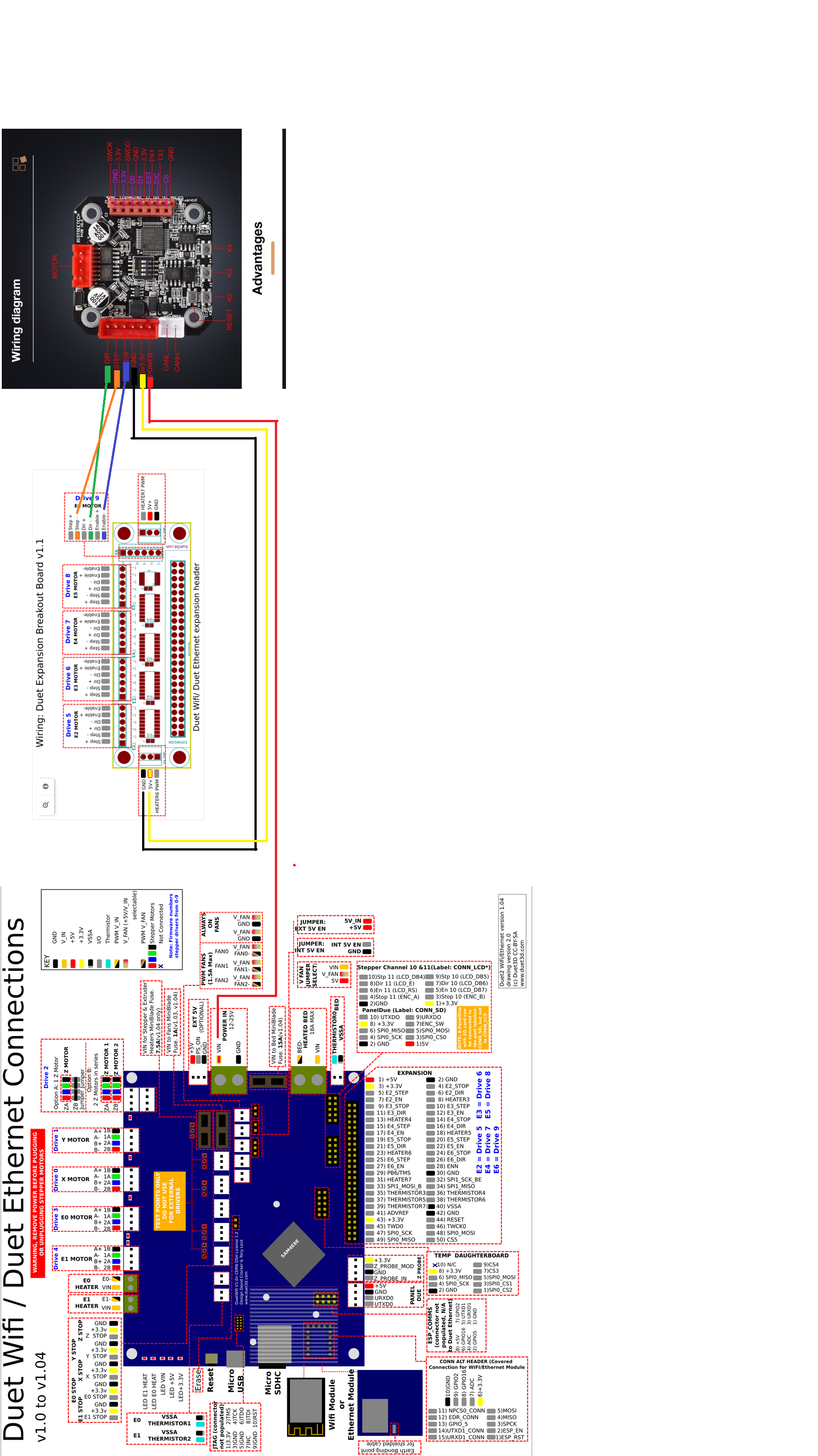
Duet Wifi Closed Loop and Panel Due
-
Update your firmware to 3.3 final for the duet and the panel.
Make sure the panel baud rate in the setup page matches the value in config.g
Have you tried the 4 wire connection method yet?
-
@phaedrux The Panel Due now works. Thanks. But how should I wire the stepper motor drivers from the breakout board?
-
Have you seen this page?
https://duet3d.dozuki.com/Wiki/Duet_Expansion_Breakout_BoardDo you have any information on how that board uses the step/direction/enable pins? I'm not familiar with that board myself.
-
@phaedrux I have seen that post and no I am not familiar with the wiring of the closed loop driver that's why I asked LOL. Do you know anyone who might be?
-
Do you have a link for the big tree tech board?
-
@phaedrux @Phaedrux here is a bit of information about the S42B v2.0: https://github.com/bigtreetech/BIGTREETECH-Stepper-Motor-Driver/tree/master/S42B/V2.0
On page 11-12 of the first document is some information about dir/step/enable.The link was from https://www.reddit.com/r/BIGTREETECH/comments/l0xtgs/btt_s42b_v20_not_working_properly_what_am_i/, mentioning, that the dip switch documentation may be wrong.
-
I don't know enough to be able to help with the original poster's questions, but I have one of my own.
What do people think they are going to achieve using a closed-loop control board between their path creation machine (Duet) and their stepper motor?
My experience measuring command-vs-actual positions showed that the stepper motor positions dramatically lagged the commanded position, and the position bounced all around at the beginning and end of moves. It would have produce terrible 3D prints.
Do people think this is going to produce a more accurate position-control for their systems, because it's likely to not do that.
This system is VERY different from the one being planned where the path-generating software and the closed-loop software are both running on the same machine like the new Duet closed-loop system being tested now.
It would be interesting to see if anyone has gotten an external closed-loop system like this to NOT produce worse results then a properly-loaded open-loop system.
-
@alankilian @JoergS5 Does this mean you guys can help me? I have no idea as per which connector on the breadboard connects to which connector on the closed loop board.
-
Did you take a look at the manual from that github link?
Have you tried connecting the step/direction/enable from the breakout board to the closed loop board yet?
-
@phaedrux I have, no luck.
-
-
@alankilian Which Pin connector should the GND, 5V/3.3V, & Power 12V/24V connect to on the Expansion board?
-
This post is deleted! -
This post is deleted! -
@gost101 Connect GND and +5 Volts from one of the two Heater connectors.
You'll need to get 12 or 24 Volts from the Duet mainboard.
-
@alankilian Is there a 12v connector on the board I can use?
-
@gost101 assuming you're using a 12V PSU, just take it straight from that. The Duet WiFi doesn't have an internal 12V regulator, so if you have a 24V PSU, you can only supply 24v
-
@alankilian Thats what I thought but wasn't entirely sure. I'll let you know if it works, when I get back home.
-
I made a quick wiring diagram in paint.

-
@alankilian @I have 5 closed loop stepper drivers for context. Can I connect all of the closed loops stepper drivers to the same 5V and Ground Terminal or would that break something?